EP0174735B1 - Method of producing a permanent magnet having high and low coercivity regions - Google Patents
Method of producing a permanent magnet having high and low coercivity regions Download PDFInfo
- Publication number
- EP0174735B1 EP0174735B1 EP19850305656 EP85305656A EP0174735B1 EP 0174735 B1 EP0174735 B1 EP 0174735B1 EP 19850305656 EP19850305656 EP 19850305656 EP 85305656 A EP85305656 A EP 85305656A EP 0174735 B1 EP0174735 B1 EP 0174735B1
- Authority
- EP
- European Patent Office
- Prior art keywords
- hot
- magnet
- regions
- die
- permanent magnet
- Prior art date
- Legal status (The legal status is an assumption and is not a legal conclusion. Google has not performed a legal analysis and makes no representation as to the accuracy of the status listed.)
- Expired
Links
Images
Classifications
-
- H—ELECTRICITY
- H01—ELECTRIC ELEMENTS
- H01F—MAGNETS; INDUCTANCES; TRANSFORMERS; SELECTION OF MATERIALS FOR THEIR MAGNETIC PROPERTIES
- H01F1/00—Magnets or magnetic bodies characterised by the magnetic materials therefor; Selection of materials for their magnetic properties
- H01F1/01—Magnets or magnetic bodies characterised by the magnetic materials therefor; Selection of materials for their magnetic properties of inorganic materials
- H01F1/03—Magnets or magnetic bodies characterised by the magnetic materials therefor; Selection of materials for their magnetic properties of inorganic materials characterised by their coercivity
- H01F1/032—Magnets or magnetic bodies characterised by the magnetic materials therefor; Selection of materials for their magnetic properties of inorganic materials characterised by their coercivity of hard-magnetic materials
- H01F1/04—Magnets or magnetic bodies characterised by the magnetic materials therefor; Selection of materials for their magnetic properties of inorganic materials characterised by their coercivity of hard-magnetic materials metals or alloys
- H01F1/047—Alloys characterised by their composition
- H01F1/053—Alloys characterised by their composition containing rare earth metals
- H01F1/055—Alloys characterised by their composition containing rare earth metals and magnetic transition metals, e.g. SmCo5
- H01F1/057—Alloys characterised by their composition containing rare earth metals and magnetic transition metals, e.g. SmCo5 and IIIa elements, e.g. Nd2Fe14B
- H01F1/0571—Alloys characterised by their composition containing rare earth metals and magnetic transition metals, e.g. SmCo5 and IIIa elements, e.g. Nd2Fe14B in the form of particles, e.g. rapid quenched powders or ribbon flakes
- H01F1/0575—Alloys characterised by their composition containing rare earth metals and magnetic transition metals, e.g. SmCo5 and IIIa elements, e.g. Nd2Fe14B in the form of particles, e.g. rapid quenched powders or ribbon flakes pressed, sintered or bonded together
- H01F1/0576—Alloys characterised by their composition containing rare earth metals and magnetic transition metals, e.g. SmCo5 and IIIa elements, e.g. Nd2Fe14B in the form of particles, e.g. rapid quenched powders or ribbon flakes pressed, sintered or bonded together pressed, e.g. hot working
Definitions
- This invention relates to a method of producing permanent magnets having at least two separate regions of different magnetic alignment as specified in the preamble of claim 1, for example as disclosed in Patent Abstracts of Japan, vol.8, no.81 (E-238) [1518] of 13 April, 1984. More particularly, this invention concerns iron, neodymium and/or praseodymium, and boron-containing permanent magnet bodies that have been hot worked so as to contain distinct regions of different alignment --e.g., one of relatively high apparent coercivity and one of relatively high remanence.
- High energy product, high coercivity permanent magnet compositions comprising, for example, iron, neodymium and/or praseodymium, and boron and methods of making them are disclosed in European published patent applications EP-A-0 108 474 and EP-A-0 144 112.
- An illustrative composition, expressed in atomic proportions, is Nd 0.13 (Fe 0.95 B 0.05 ) 0.87 . It is a composition containing a specific stable intermetallic phase and that possesses high coercivity when formed as fine crystallites about 20 to 400 nanometers in largest dimension.
- melts of suitable iron-light rare earth metal-boron compositions can be very rapidly quenched, such as by melt-spinning, to produce a solid material, e.g., a thin ribbon.
- a solid material e.g., a thin ribbon.
- the rate of cooling has been controlled to produce a suitable fine crystalline microstructure (20 nm to 400 nm)
- the material has excellent permanent magnet properties.
- faster cooling overquenching
- overquenched material can be annealed to form the suitable crystal size with the associated high coercivity and high energy product.
- this neodymium-iron-boron composition is that it is substantially magnetically isotropic.
- a fine grain, melt-spun ribbon can be broken up into flat particles. The particles can be pressed in a die at room temperature to form a unitary body of a density about 85% that of the material. Bonding agents can be employed before or after the compaction. The making of such bonded magnets is disclosed in European published patent application EP-A-0 125 752. It was surprising to find that such bonded magnets displayed no preferred magnetic direction. Values of intrinsic coercivity or maximum energy product were not dependent upon the direction of the applied magnetic field. There was no advantage in grinding the ribbon to very fine particles and magnetically aligning the particles before compaction.
- Such magnetically isotropic materials are very useful because they can be easily pressed (without magnetic alignment) into bonded shapes.
- the shapes can be magnetized in the most convenient direction.
- the iron, neodymium, boron type compositions have also been processed by hot-pressing and hot-working so that at least a portion of the grains or crystallites was physically aligned producing at least partial magnetic alignment.
- hot-worked materials had a preferred direction of magnetization.
- a molten material containing, in terms of atomic proportions, Nd 0.13 (Fe 0.95 B 0.05 ) 0.87 is cooled extremely rapidly, as by melt-spinning, to form a thin ribbon of solid material that did not have permanent magnet properties.
- the material was amorphous in microstructure.
- the ribbon was broken into particles of convenient size for a hot-working operation.
- the particles were heated under argon to about 700 o C or higher in a die and pressed with punches in the die under pressure of at least 68947.6 kPa (10,000 psi).
- Such hot-working hereafter termed hot-pressing, consolidated the particles into a fully dense body.
- a method of producing a permanent magnet body is characterised by the features specified in the characterising portion of claim 1.
- Application of the method to rapidly cooled compositions comprising iron, neodymium and/or praseodymium and boron is particularly contemplated.
- An example of such a magnetic structure is an arcuate magnet for a permanent magnet motor. It is contemplated that one or both of the circumferential edges of the arc would be worked so as to have relatively high coercivity and the central portion of the arc would have a relatively higher remanence. Again, it is especially contemplated that the magnet would be of the above described iron-light rare earth metal-boron compositions.
- the starting material is a rapidly-quenched composition comprising iron, neodymium and/or praseodymium, and boron.
- An example of a suitable composition is one consisting, in terms of atomic proportion, of Nd 0.13 (Fe 0.95 B 0.05 ) 0.87 .
- the starting material is amorphous in microstructure or characterized by an extremely fine crystalline structure. It is preferred to start with such an amorphous or fine grained microstructure so that the hot-working can be carried out without loss of suitable coercivity in the final product.
- Particles of melt-spun material are placed in the cavity of an open-ended die between two opposing punches.
- the particles are heated in the die to a temperature, suitably about 700 o C or higher, and compacted at a suitable pressure to form a fully densified body.
- Split-ram punches may be employed, as will be described, such that the consolidated body has a stepwise variation in thickness over its cross-section within the die. While still in the hot die, the respective punch edges (of the split ram) may then be brought into alignment and moved in concert to subject a portion of the consolidated part to further hot-working. Such hot-working strains the thick portion of the irregular consolidated part differently than the thin portion. The different strain over the cross-section produces two regions of generally different magnetic alignment.
- the region that is most highly strained in the direction perpendicular to the press direction is more highly aligned and has a demagnetization curve like that of curve B in Figure 1.
- the region that was not deformed (or less deformed) by the second press operation has less magnetic alignment and displays magnetic properties like that of curve A in Figure 1.
- a typical application for the invention is an arcuate motor magnet in which the leading edge of the arcuate magnet (in a motor that rotates in one direction only) is subjected to a higher demagnetization force than the rest of the arcuate magnet.
- the leading edge of the arcuate magnet would be processed so as to have high apparent coercivity (measured radially with respect to the arcuate magnet) and the rest of the arcuate magnet would be hot-worked so as to have relatively high remanence and maximum energy product.
- the present invention is applicable to permanent magnet compositions that can be magnetically aligned by plastic deformation of the material at elevated temperatures.
- An example of a family of preferred compositions to which the method of the invention is applicable is the transition metal-rare earth metal-boron materials described in the above-identified patent applications.
- the invention is particularly applicable to compositions in which the transition metal component is iron or iron and (one or more of) cobalt, nickel, chromium or manganese. Cobalt is interchangeable with iron up to about 40 atomic percent. Chromium, manganese and nickel are interchangeable in lower amounts, preferably less than 10 atomic percent. Zirconium and/or titanium in small amounts (up to 2 atomic percent of the iron) can be substituted for iron. Very small amounts of carbon and silicon can be tolerated where low carbon steel is the source of iron for the composition.
- the composition preferably comprises about 50 atomic percent to about 90 atomic percent transition metal component -- largely iron.
- the composition also comprises from about 10 atomic percent to about 50 atomic percent rare earth component.
- Neodymium and/or praseodymium are the essential rare earth constituents. As indicated, they may be used interchangeably. Relatively small amounts of other rare earth elements, such as samarium, lanthanum, cerium, terbium and dysprosium, may be mixed with neodymium and praseodymium without substantial loss of the desirable magnetic properties. Preferably, they make up no more than about 40 atomic percent of the rare earth component. It is expected that there will be small amounts of impurity elements with the rare earth component.
- the overquenched composition contains about 1 to 10 atomic percent boron.
- the overall composition may be expressed by the formula RE 1-x (TM 1-y B y ) x .
- the transition metal (TM) as used herein makes up about 50 to 90 atomic percent of the overall composition, with iron representing at least 60 atomic percent of the transition metal content.
- the other constituents, such as cobalt, nickel, chromium and manganese, are called "transition metals" insofar as the above empirical formula is concerned.
- compositions For convenience, the compositions have been expressed in terms of atomic proportions. Obviously these specifications can be readily converted to weight proportions for preparing the composition mixtures.
- the method of the invention is applicable to other compositions as described above.
- molten transition metal-rare earth-boron compositions can be solidified to have microstructures ranging from:
- Suitable overquenched compositions can be made by melt-spinning. Melt-spinning is described in the above applications and will not be repeated here. It is also practiced commercially to produce nonmagnetic or soft magnetic alloys. It is preferrable to use melt-spun materials that have been cooled at such a rate that an amorphous or extremely fine crystal structure is produced. In the case of the iron-neodymium-boron compositions, it is preferrable to start with a rapidly solidified structure having a grain size smaller than about 20 nanometers.
- the material is then heated and worked in a die at a temperature of about 700-750 o C to consolidate particles of the material into a fully densified mass and then to selectively deform the consolidated material plastically to achieve regions of different magnetic alignment.
- Such processing is carried out fairly rapidly so that excessive grain growth does not occur and the permanent magnet characteristics lost.
- Figure 1 graphically depicts the demagnetization properties of a hot-pressed iron-neodymium-boron magnet (curve A) and a die-upset magnet (curve B) of the same composition.
- the hot-pressed magnet is only moderately magnetically aligned and possesses a relatively high degree of coercivity in the press direction.
- the die-upset magnet has been signifcantly plastically deformed. The material has attained a relatively high degree of alignment. Its coercivity in the press direction has thereby been decreased but its remanence increased.
- the hot-worked magnets display magnetic alignment in a direction perpendicular to the direction of plastic flow.
- the magnetic alignment is parallel to the press direction.
- the magnetic properties, e.g., coercivity and remanence, of such anisotropic magnets are measured, the values measured in the preferred (aligned) direction are detected and reported unless otherwise stated.
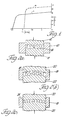
- FIG. 2 illustrates the method of forming a die-upset magnetically aligned arcuate permanent magnet.
- Particles of melt-spun material are loaded into a cavity formed by open-ended die 10 and vertically aligned opposing punches 12 and 14 such as is shown in Figure 2(a).
- the die and its contacts are heated by an induction heater (not shown) to a temperature at or near 700 o C.
- the punches 12 and 14 compact the particulate material under a pressure of, for example, 103421.4 kPa (15,000 psi) to form a substantially fully densified body 16 depicted in the die cavity in Figure 2(a).
- the arrows within the outline of body 16 indicate that the densified compact is substantially unaligned. However, there is a slight alignment preference in the direction of compaction.
- the magnetic properties of this compact are like that depicted in curve A of Figure 1.
- the compact 16 is then transferred to a larger die 18 with opposing punches 20 and 22 as shown in Figure 2(b).
- the cavity is likewise heated to maintain the compact 16 at a temperature at or near 700 o C.
- the compact 16 is then plastically deformed by the punches 20 and 22 to form die-upset arcuate body 24.
- the material flows laterally, but the direction of alignment, and easy magnetization, is transverse to the plastic flow, i.e., generally in the direction of pressing as shown by the arrows in Figure 2(c).
- the resulting arcuate magnet 24 is wider and thinner than compact 16.
- Magnet 24 has a high degree of magnetic alignment which is substantially uniformly radial with respect to the centre of curvature. Magnet 24 is shown in section in Figure 2(c). In perspective view it would appear like the magnet 36 shown in Figure 4(b).
- Such arcuate magnet 24 could be produced by the practice described in the above cited European patent application EP-A-0 133 758.
- an arcuate magnet or other permanent magnet structure is produced in which there are at least two regions in the unitary body having different magnetic alignment.
- this is accomplished by first making a densified hot-pressed compact having sections of different thickness.
- a convenient practice is to form a compact having abrupt or stepped differences in thickness.
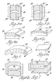
- This can be accomplished by using a split ram die as depicted in Figure 3.
- such a die uses a conventional die body 25, but both the upper 26 and lower 28 punches are split and the two portions (26', 26'' and 28', 28'') of each punch can either move in concert as shown in Figure 3(a) or move separately as shown in Figure 3(b).
- Such a split punch or split ram die arrangement can be employed to hot-press and consolidate particulate melt-spun material to form a compact like that depicted in Figure 4(a).
- the arcuate hot-pressed compact 30 of Figure 4(a) is of substantially uniform density and random magnetic alignment (or disalignment), but it has a stepwise change in thickness.
- the perspective view ( Figure 4(a)) of arcuate compact 30 shows a relatively thick portion 32 and adjacent thin section 34.
- the compact 30 has a chord length L. It can be produced in a split ram die in which the split punches are operated as shown in Figure 3(b).
- the formation of a hot-pressed, densified compact 30 of such a configuration permits the making of a die-upset arcuate compact of uniform thickness but having regions of different magnetic alignment.
- Region 40 has magnetization characteristics like that of curve A of Figure 1, and region 38 has magnetic characteristics like that of curve B.
- the right circumferential edge portion 40, as seen in Figure 4(b), of the arcuate magnet 36 has a higher coercivity than the rest of the one-piece magnet. This characteristic is particularly useful in arcuate pole pieces of a DC motor where the demagnetisation forces act most severely on the leading edge of the magnet.
- Figure 5 is an end view of a two-region magnet 42 illustrating a general principle of the present invention.
- One (or both) arcuate edge (region 46) of magnet 42 has a magnetic orientation as schematically illustrated by the direction of the arrows of the Figure that are oriented at an angle theta ( ⁇ ⁇ 0) with respect to the radial direction of the arc.
- the remaining portion 44 of the magnet has been worked so that it is magnetically oriented radially with respect to the centre of curvature, as shown by the arrows in region 44.
- both regions 44 and 46 are highly aligned and have relatively high remanence in the alignment direction.
- edge region 46 is more difficult to demagnetize by the reverse field generated by a motor armature.
- a two-part magnet is another embodiment of the present invention.
- a two-part magnet like that depicted in Figure 5 can be produced by a practice illustrated in Figures 6(a) and (b).
- a die-upset permanent magnet 48 of the warped configuration depicted in Figure 6(a) is produced.
- a hot-pressed compact is first made and then die-upset into the Figure 6(a) configuration with strain occurring in the direction indicated.
- the die-upset magnet 48 is warped, the magnetic orientation is parallel across the entire end section. While still warm, the warped body 48 is bent in a die 50 between opposed punches 52 and 54 into an arcuate permanent magnet like 42 in Figure 5.
- the reversed bending of the warped starting magnet produces an arcuate magnet (like 42) having regions (like 44 and 46) of different magnetic alignment as illustrated in Figure 5.
- Figure 7 illustrates yet another die-forming practice of producing a two-part permanent magnet in accordance with the present invention.
- a hot-pressed uncurved compact 56 of stepwise difference in thickness is first produced.
- the compact 56 has a relatively thick portion 58 and a thin portion 60. This is accomplished in die 62 using split punches 64 and 66 operated in stepped relationship. The punches are then slightly withdrawn and employed in concert to produce thinning of the thick portion 58 of the compact and thickening of the thin portion 60 of the compact 56.
- the result in this instance is a flat body 68 (dashed lines) having regions of different magnetic alignment resulting from regions of different plastic flow.
- the arrows depict strain direction rather than magnetization direction. The latter would be perpendicular to the strain as previously stated.
- a unitary body of magnetic material is produced that has two or more regions of different magnetic alignment. It is preferred that the regions be separated along a surface direction rather than one region being contained within another. This separation of regions along a surface dimension is illustrated by regions 38 and 40 in arcuate magnet 36 and regions 44 and 46 in arcuate magnet 42. In both cases the regions are separated in the circumferential direction of the arc.
- the regions of different magnetic alignment are produced by selectively hot-working different parts of the body of magnetic material in different ways. Different portions of the body are caused to undergo different degrees of strain at elevated temperature or the strain is induced in different directions. This can be accomplished, for example, by starting with a densified compact of varying thickness and die-upsetting it to produce a product of uniform thickness.
- a body of magnetic material of uniformly parallel alignment may be bent at elevated temperature (as illustrated in Figure 6) to produce the two-part magnet structure.
- the invention can also be practiced by using a previously hot-pressed compact in combination with particles of melt-spun ribbon.
- the compact By hot-working the compact and particles in different regions of the same die, the compact may be die-upset (for example) and the particles hot-pressed to full density (or nearly full density) with it to form a unitary body having regions of different alignment.
- one may employ different compositions for the initial compact and for the added particles.
- the present invention is particularly useful in making transition metal-rare earth-boron magnets of the type described above. However, it may also be utilized with other magnetic compositions that can be magnetically aligned by plastic deformation at a suitable elevated temperature.
- permanent magnet or "hard magnet” as used herein mean a material having a significant intrinsic coercivity at room temperature, e.g., greater than 79,600 A/m (1000 oersted).
Landscapes
- Chemical & Material Sciences (AREA)
- Crystallography & Structural Chemistry (AREA)
- Inorganic Chemistry (AREA)
- Engineering & Computer Science (AREA)
- Power Engineering (AREA)
- Manufacturing Cores, Coils, And Magnets (AREA)
- Hard Magnetic Materials (AREA)
Applications Claiming Priority (2)
| Application Number | Priority Date | Filing Date | Title |
|---|---|---|---|
| US65062384A | 1984-09-14 | 1984-09-14 | |
| US650623 | 1984-09-14 |
Publications (3)
| Publication Number | Publication Date |
|---|---|
| EP0174735A2 EP0174735A2 (en) | 1986-03-19 |
| EP0174735A3 EP0174735A3 (en) | 1988-01-20 |
| EP0174735B1 true EP0174735B1 (en) | 1991-09-11 |
Family
ID=24609632
Family Applications (1)
| Application Number | Title | Priority Date | Filing Date |
|---|---|---|---|
| EP19850305656 Expired EP0174735B1 (en) | 1984-09-14 | 1985-08-09 | Method of producing a permanent magnet having high and low coercivity regions |
Country Status (7)
| Country | Link |
|---|---|
| EP (1) | EP0174735B1 (enExample) |
| JP (1) | JPS6174305A (enExample) |
| AU (1) | AU580618B2 (enExample) |
| BR (1) | BR8504369A (enExample) |
| CA (1) | CA1244322A (enExample) |
| DE (1) | DE3584061D1 (enExample) |
| ES (1) | ES8707373A1 (enExample) |
Families Citing this family (18)
| Publication number | Priority date | Publication date | Assignee | Title |
|---|---|---|---|---|
| CA1244322A (en) * | 1984-09-14 | 1988-11-08 | Robert W. Lee | Hot pressed permanent magnet having high and low coercivity regions |
| US6136099A (en) * | 1985-08-13 | 2000-10-24 | Seiko Epson Corporation | Rare earth-iron series permanent magnets and method of preparation |
| US5125988A (en) * | 1987-03-02 | 1992-06-30 | Seiko Epson Corporation | Rare earth-iron system permanent magnet and process for producing the same |
| US5538565A (en) * | 1985-08-13 | 1996-07-23 | Seiko Epson Corporation | Rare earth cast alloy permanent magnets and methods of preparation |
| JP2530641B2 (ja) * | 1986-03-20 | 1996-09-04 | 日立金属株式会社 | 磁気異方性ボンド磁石、それに用いる磁粉及びその製造方法 |
| IT1206056B (it) * | 1986-06-20 | 1989-04-05 | Seiko Epson Corp | Procedimento per la preparazione di magneti permanenti e prodotto ottenuto |
| US4983232A (en) * | 1987-01-06 | 1991-01-08 | Hitachi Metals, Ltd. | Anisotropic magnetic powder and magnet thereof and method of producing same |
| KR900006533B1 (ko) * | 1987-01-06 | 1990-09-07 | 히다찌 긴조꾸 가부시끼가이샤 | 이방성 자성분말과 이의 자석 및 이의 제조방법 |
| US5213631A (en) * | 1987-03-02 | 1993-05-25 | Seiko Epson Corporation | Rare earth-iron system permanent magnet and process for producing the same |
| US4888506A (en) * | 1987-07-09 | 1989-12-19 | Hitachi Metals, Ltd. | Voice coil-type linear motor |
| JPH07105301B2 (ja) * | 1987-09-10 | 1995-11-13 | 日立金属株式会社 | 磁気異方性Nd―Fe―B磁石材の製法 |
| JPS6472502A (en) * | 1987-09-11 | 1989-03-17 | Hitachi Metals Ltd | Permanent magnet for accelerating particle beam |
| US4859410A (en) * | 1988-03-24 | 1989-08-22 | General Motors Corporation | Die-upset manufacture to produce high volume fractions of RE-Fe-B type magnetically aligned material |
| JP3037699B2 (ja) * | 1988-09-30 | 2000-04-24 | 日立金属株式会社 | 耐割れ性及び配向性を改善した温間加工磁石ならびにその製造方法 |
| US5098486A (en) * | 1989-05-23 | 1992-03-24 | Hitachi Metals, Ltd. | Magnetically anisotropic hotworked magnet and method of producing same |
| US4952251A (en) * | 1989-05-23 | 1990-08-28 | Hitachi Metals, Ltd. | Magnetically anisotropic hotworked magnet and method of producing same |
| JP5707934B2 (ja) * | 2010-12-27 | 2015-04-30 | トヨタ自動車株式会社 | 異方性永久磁石の製造方法 |
| JP6330438B2 (ja) * | 2014-04-09 | 2018-05-30 | 信越化学工業株式会社 | 希土類焼結磁石の製造方法 |
Family Cites Families (5)
| Publication number | Priority date | Publication date | Assignee | Title |
|---|---|---|---|---|
| CS213750B1 (en) * | 1979-08-03 | 1982-04-09 | Vaclav Landa | Method of making the anizotropic permanent magnets |
| DE3248846T1 (de) * | 1981-07-14 | 1983-07-07 | Hitachi Metals, Ltd., Tokyo | Verbundpermanentmagnet fuer die magnetische erregung und verfahren zu seiner herstellung |
| DE3379131D1 (en) * | 1982-09-03 | 1989-03-09 | Gen Motors Corp | Re-tm-b alloys, method for their production and permanent magnets containing such alloys |
| CA1216623A (en) * | 1983-05-09 | 1987-01-13 | John J. Croat | Bonded rare earth-iron magnets |
| CA1244322A (en) * | 1984-09-14 | 1988-11-08 | Robert W. Lee | Hot pressed permanent magnet having high and low coercivity regions |
-
1985
- 1985-07-12 CA CA000486721A patent/CA1244322A/en not_active Expired
- 1985-08-09 EP EP19850305656 patent/EP0174735B1/en not_active Expired
- 1985-08-09 DE DE8585305656T patent/DE3584061D1/de not_active Expired - Lifetime
- 1985-08-21 AU AU46487/85A patent/AU580618B2/en not_active Ceased
- 1985-09-10 BR BR8504369A patent/BR8504369A/pt not_active IP Right Cessation
- 1985-09-13 ES ES546960A patent/ES8707373A1/es not_active Expired
- 1985-09-14 JP JP20256385A patent/JPS6174305A/ja active Granted
Also Published As
| Publication number | Publication date |
|---|---|
| AU580618B2 (en) | 1989-01-19 |
| ES8707373A1 (es) | 1987-07-16 |
| EP0174735A2 (en) | 1986-03-19 |
| ES546960A0 (es) | 1987-07-16 |
| AU4648785A (en) | 1986-03-20 |
| DE3584061D1 (de) | 1991-10-17 |
| EP0174735A3 (en) | 1988-01-20 |
| JPH0315806B2 (enExample) | 1991-03-04 |
| CA1244322A (en) | 1988-11-08 |
| JPS6174305A (ja) | 1986-04-16 |
| BR8504369A (pt) | 1986-07-08 |
Similar Documents
| Publication | Publication Date | Title |
|---|---|---|
| US4710239A (en) | Hot pressed permanent magnet having high and low coercivity regions | |
| EP0174735B1 (en) | Method of producing a permanent magnet having high and low coercivity regions | |
| EP0187538B1 (en) | Permanent magnet and method for producing same | |
| EP0133758B1 (en) | Iron-rare earth-boron permanent magnets by hot working | |
| US5352301A (en) | Hot pressed magnets formed from anisotropic powders | |
| US5049203A (en) | Method of making rare earth magnets | |
| JPH01704A (ja) | 希土類−鉄系永久磁石 | |
| JPS62276803A (ja) | 希土類−鉄系永久磁石 | |
| EP0348038B1 (en) | Manufacturing method of a permanent magnet | |
| USRE34838E (en) | Permanent magnet and method for producing same | |
| US5049335A (en) | Method for making polycrystalline flakes of magnetic materials having strong grain orientation | |
| JPS62203302A (ja) | 鋳造希土類―鉄系永久磁石の製造方法 | |
| EP0288637B1 (en) | Permanent magnet and method of making the same | |
| JPS63178505A (ja) | 異方性R−Fe−B−M系永久磁石 | |
| JP2745042B2 (ja) | 希土類−鉄−ボロン系合金薄板、合金粉末及び永久磁石の製造方法 | |
| JP2857824B2 (ja) | 希土類−鉄系永久磁石の製造方法 | |
| CA2034632C (en) | Hot worked rare earth-iron-carbon magnets | |
| JPS63286515A (ja) | 永久磁石の製造方法 | |
| JP2631380B2 (ja) | 希土類―鉄系永久磁石の製造方法 | |
| JPH04187722A (ja) | 永久磁石の製造方法 | |
| JPH01175207A (ja) | 永久磁石の製造方法 | |
| JPS63107009A (ja) | 永久磁石の製造方法 | |
| JPS63286514A (ja) | 永久磁石の製造方法 | |
| JPS63213323A (ja) | 希土類−鉄系永久磁石 | |
| JPH01175209A (ja) | 永久滋石の製造方法 |
Legal Events
| Date | Code | Title | Description |
|---|---|---|---|
| PUAI | Public reference made under article 153(3) epc to a published international application that has entered the european phase |
Free format text: ORIGINAL CODE: 0009012 |
|
| 17P | Request for examination filed |
Effective date: 19850819 |
|
| AK | Designated contracting states |
Kind code of ref document: A2 Designated state(s): DE FR GB IT NL SE |
|
| PUAL | Search report despatched |
Free format text: ORIGINAL CODE: 0009013 |
|
| AK | Designated contracting states |
Kind code of ref document: A3 Designated state(s): DE FR GB IT NL SE |
|
| 17Q | First examination report despatched |
Effective date: 19900627 |
|
| ITF | It: translation for a ep patent filed | ||
| GRAA | (expected) grant |
Free format text: ORIGINAL CODE: 0009210 |
|
| AK | Designated contracting states |
Kind code of ref document: B1 Designated state(s): DE FR GB IT NL SE |
|
| REF | Corresponds to: |
Ref document number: 3584061 Country of ref document: DE Date of ref document: 19911017 |
|
| ET | Fr: translation filed | ||
| PLBE | No opposition filed within time limit |
Free format text: ORIGINAL CODE: 0009261 |
|
| STAA | Information on the status of an ep patent application or granted ep patent |
Free format text: STATUS: NO OPPOSITION FILED WITHIN TIME LIMIT |
|
| 26N | No opposition filed | ||
| EAL | Se: european patent in force in sweden |
Ref document number: 85305656.2 |
|
| PGFP | Annual fee paid to national office [announced via postgrant information from national office to epo] |
Ref country code: GB Payment date: 19950814 Year of fee payment: 11 |
|
| PGFP | Annual fee paid to national office [announced via postgrant information from national office to epo] |
Ref country code: SE Payment date: 19950821 Year of fee payment: 11 |
|
| PGFP | Annual fee paid to national office [announced via postgrant information from national office to epo] |
Ref country code: FR Payment date: 19950829 Year of fee payment: 11 |
|
| PGFP | Annual fee paid to national office [announced via postgrant information from national office to epo] |
Ref country code: NL Payment date: 19950831 Year of fee payment: 11 |
|
| PGFP | Annual fee paid to national office [announced via postgrant information from national office to epo] |
Ref country code: DE Payment date: 19950927 Year of fee payment: 11 |
|
| PG25 | Lapsed in a contracting state [announced via postgrant information from national office to epo] |
Ref country code: GB Effective date: 19960809 |
|
| PG25 | Lapsed in a contracting state [announced via postgrant information from national office to epo] |
Ref country code: SE Effective date: 19960810 |
|
| PG25 | Lapsed in a contracting state [announced via postgrant information from national office to epo] |
Ref country code: NL Effective date: 19970301 |
|
| GBPC | Gb: european patent ceased through non-payment of renewal fee |
Effective date: 19960809 |
|
| PG25 | Lapsed in a contracting state [announced via postgrant information from national office to epo] |
Ref country code: FR Effective date: 19970430 |
|
| NLV4 | Nl: lapsed or anulled due to non-payment of the annual fee |
Effective date: 19970301 |
|
| PG25 | Lapsed in a contracting state [announced via postgrant information from national office to epo] |
Ref country code: DE Effective date: 19970501 |
|
| EUG | Se: european patent has lapsed |
Ref document number: 85305656.2 |
|
| REG | Reference to a national code |
Ref country code: FR Ref legal event code: ST |