EP0348038B1 - Manufacturing method of a permanent magnet - Google Patents
Manufacturing method of a permanent magnet Download PDFInfo
- Publication number
- EP0348038B1 EP0348038B1 EP89305021A EP89305021A EP0348038B1 EP 0348038 B1 EP0348038 B1 EP 0348038B1 EP 89305021 A EP89305021 A EP 89305021A EP 89305021 A EP89305021 A EP 89305021A EP 0348038 B1 EP0348038 B1 EP 0348038B1
- Authority
- EP
- European Patent Office
- Prior art keywords
- magnetic
- hot
- atomic
- magnet
- phase
- Prior art date
- Legal status (The legal status is an assumption and is not a legal conclusion. Google has not performed a legal analysis and makes no representation as to the accuracy of the status listed.)
- Expired - Lifetime
Links
Images


Classifications
-
- H—ELECTRICITY
- H01—ELECTRIC ELEMENTS
- H01F—MAGNETS; INDUCTANCES; TRANSFORMERS; SELECTION OF MATERIALS FOR THEIR MAGNETIC PROPERTIES
- H01F41/00—Apparatus or processes specially adapted for manufacturing or assembling magnets, inductances or transformers; Apparatus or processes specially adapted for manufacturing materials characterised by their magnetic properties
- H01F41/02—Apparatus or processes specially adapted for manufacturing or assembling magnets, inductances or transformers; Apparatus or processes specially adapted for manufacturing materials characterised by their magnetic properties for manufacturing cores, coils, or magnets
- H01F41/0253—Apparatus or processes specially adapted for manufacturing or assembling magnets, inductances or transformers; Apparatus or processes specially adapted for manufacturing materials characterised by their magnetic properties for manufacturing cores, coils, or magnets for manufacturing permanent magnets
- H01F41/0273—Imparting anisotropy
-
- H—ELECTRICITY
- H01—ELECTRIC ELEMENTS
- H01F—MAGNETS; INDUCTANCES; TRANSFORMERS; SELECTION OF MATERIALS FOR THEIR MAGNETIC PROPERTIES
- H01F1/00—Magnets or magnetic bodies characterised by the magnetic materials therefor; Selection of materials for their magnetic properties
- H01F1/01—Magnets or magnetic bodies characterised by the magnetic materials therefor; Selection of materials for their magnetic properties of inorganic materials
- H01F1/03—Magnets or magnetic bodies characterised by the magnetic materials therefor; Selection of materials for their magnetic properties of inorganic materials characterised by their coercivity
- H01F1/032—Magnets or magnetic bodies characterised by the magnetic materials therefor; Selection of materials for their magnetic properties of inorganic materials characterised by their coercivity of hard-magnetic materials
- H01F1/04—Magnets or magnetic bodies characterised by the magnetic materials therefor; Selection of materials for their magnetic properties of inorganic materials characterised by their coercivity of hard-magnetic materials metals or alloys
- H01F1/047—Alloys characterised by their composition
- H01F1/053—Alloys characterised by their composition containing rare earth metals
- H01F1/055—Alloys characterised by their composition containing rare earth metals and magnetic transition metals, e.g. SmCo5
- H01F1/057—Alloys characterised by their composition containing rare earth metals and magnetic transition metals, e.g. SmCo5 and IIIa elements, e.g. Nd2Fe14B
- H01F1/0571—Alloys characterised by their composition containing rare earth metals and magnetic transition metals, e.g. SmCo5 and IIIa elements, e.g. Nd2Fe14B in the form of particles, e.g. rapid quenched powders or ribbon flakes
- H01F1/0575—Alloys characterised by their composition containing rare earth metals and magnetic transition metals, e.g. SmCo5 and IIIa elements, e.g. Nd2Fe14B in the form of particles, e.g. rapid quenched powders or ribbon flakes pressed, sintered or bonded together
- H01F1/0576—Alloys characterised by their composition containing rare earth metals and magnetic transition metals, e.g. SmCo5 and IIIa elements, e.g. Nd2Fe14B in the form of particles, e.g. rapid quenched powders or ribbon flakes pressed, sintered or bonded together pressed, e.g. hot working
Definitions
- This invention generally relates to a method of manufacturing a permanent magnet of magnetic anisotropy by means of mechanical orientation, and more particularly to a method of manufacturing a permanent magnet comprising R [at least one element selected from the group consisting of rare earth elements including Yttrium(Y)], M(at least one element selected from the group consisting of transition elements) and X(at least one element selected from the group consisting of IIIa elements of the periodic table).
- Permanent magnet is one of the important electric-electronic material used in a wide field such as that from many kinds of domestic appliance to peripheral equipments of a large scale computer, and, in consequent with the present user's request of minaturization and the improvement of efficiency of these apparatus, higher performance permanent magnet have been required.
- Permanent magnet is a material which can produce magnetic field without applying electric power and magnetic material having high coercive force and high residual magnetic flux density is suitable in use. These requirements are quite different from high permeability magnetic material, which is used at present, there are cast magnets of Alnico series, barium-ferrite magnet and a magnet of rare-earth transition metal series.
- permanent magnets of rare-earth transition metal magnet series such as R-Co series of R-Fe-B series have high magnetic properties having very high coercive force and energy-product value, therefore, much research and development have been carried out.
- Appl Phys Vol.55(6) 15 March 1984 p.2083 disclose permanent magnet characterized of magnetically anisotropic sintered substance comprised of 8-30 atomic % of R(R being at least one element selected from the group consisting of rare-earth element including Y) and residual of iron(Fe) and this substance is manufactured by means of sintering method of powder metallurgy.
- the manufacturing process is comprised of preparing alloy ingot by means of melting and casting, providing magnetic powder of suitable grain size by means of grinding, blending said powder with an additive binder for forming and forming green body by press-forming in a magnetic field. After pressing the green body is sintered in the argon atmosphere at a temperature of 1100 degree centigrade for about one hour and after that, product is rapidly cooled to a room temperature. After the sintering, product is heat-treated at 600 degree centigrade to improve coercive force.
- Japanese patent application disclosure No. 59-211549 (equivalent to EP125752) and reference by R.W. Lee; (Appl. Phys. Lett. vol. 46(8) 15 Apr. 1985 p790).
- a resin-bonded rare-earth-iron magnet which is formed from fine particles of alloy ribbon prepared by means of melt-spinning method and having fine crystalline magnetic phase and in which said alloy being comprised at least one rare earth element selected from the group consisting of neodymium, praseodymium and misch metal, transition metal element, iron and boron, characterising that said fine particles being formed in the desired shape of magnet by a binder mixed with said particles, said fine particle being magnetically isotropic, said formed magnet being magnetised to any desired direction in a proper magnetic field, said magnet having density of at least 80% of the alloy density and having energy product of at least 9 megagauss-oersted (approx. 72KJm -3 ).
- This permanent magnet is manufactured by means of resin-bonding method using rapidly quenched thin ribbon prepared by melt spinning method having process comprising providing rapidly quenched thin ribbon of about 30 micrometer thickness by means of melt spinning apparatus used to provide amorphous alloy.
- a manufacturing method of a permanent magnet said permanent magnet being anisotropic characterizing that said permanent magnet being composes of iron-rare-earth metal, and its manufacturing method comprising heat treating amorphous or fine grained solid particles including iron, neodymium and/or praseodymium and boron to prepare plastically deformed body of fine grained microstructure, cooling said body to prepare the body having anisotropic magnetic property and showing permanent magnet property.
- the manufacturing method of these magnet is a method to manufacture R-Fe-B magnet having anisotropic property and having high density by means of 2-step hot-pressing method in a vacuum or inert-gas atmosphere from a ribbon-like rapidly quenched thin ribbon or plate.
- one-axial pressure is applied to align easy magnetization direction parallel to said pressing axis to prepare anisotropically magnetizable alloy.
- particle grain size of said ribbon-like thin plate manufactured preliminary by melt-spinning method may be prepared smaller than the grain size showing maximum coercive force to give optimum grain size after the grain-growth in the hot-press process.
- Japanese patent application disclosure No. 62-276803 (equivalent to DE3626406A or U.S. Patent application No. 06/895653) discloses a permanent magnet of rare-earth-iron system which is characterized by melting an alloy comprising 8 ⁇ 30 atomic % of R (at least one element selected from the group consisting of rare-earth including Y), 2 ⁇ 28 atomic % of boron, less than 50 atomic % of cobalt, less than 15 atomic % of aluminium and rest iron and inevitable inpurities, casting said alloy, hot-working at a temperature above 500°C said cast ingot to refine crystal grain and also to orient crystal axis to a specific direction to make magnetic anisotropy said cast alloy.
- R at least one element selected from the group consisting of rare-earth including Y
- 2 ⁇ 28 atomic % of boron less than 50 atomic % of cobalt
- 15 atomic % of aluminium and rest iron and inevitable inpurities casting said alloy, hot-working at a
- Formed body which is called green body
- green body is very difficult to handle because it is easy to break.
- the handling is very troublesome when the formed bodies are arranged regularly in the sintering furnace.
- Permanent magnets in accordance to references (2) and (3) are manufactured by means of vacuum-melt spinning machine, this machine is not only very expensive but also have very low productivity at least at present.
- Permanent magnet in accordance to the reference (2) is disadvantageous not only in the temperature characteristics but also for the application thereof because it has homogeneous magnetic property so that it has low energy product and also has bad squareness of the hysteresis loop.
- the manufacturing method in accordance with reference (3) is a unique one which utilizes hot-pressing in two-steps, but when considered for use in mass-production, it is inefficient.
- the method of manufacturing a permanent magnet in accordance with the reference (4) has a problem that the manufactured magnet has somewhat inferior magnetic properties compared with that of the magnet according to references (2) or (3): although it does not include a pulverising process and has only one hot-press process thus reducing the manufacturing process to its maximum extent.
- European Patent Publication No. 0231620 which describes a method of making a permanent magnet of composition Nd 16.5 Fe 76.3 B 7.2 by chilling the molten alloy, breaking it up into particles and then hot working the particles in order to gain magnetic anisotropy by means of mechanical alignment.
- the substitution of Pr for Nd and Co for some of the Fe is suggested.
- This invention is to solve disadvantages in the traditional techniques hereinabove described, in particular, in the characteristics of the permanent magnet in accordance with the reference (4), and the object thereof is to provide an inexpensive permanent magnet but which has excellent characteristics and the manufacturing method thereof.
- a method of manufacturing a permanent magnet comprising melting and casting an alloy having a composition comprising R, R being at least one element selected from the group consisting of rare-earth elements including Y, M, M being at least one element selected from the group consisting of transition metal elements and X, X being at least one element selected from the group consisting of IIIa group of the periodic table, heating and compressing said cast alloy at a temperature of 500°C or above characterised by said heating and compressing squeezing the non-magnetic R-rich phase to the outside edges of the alloy and by removal of at least part of the thus squeezed out R-rich phase whereby the volume fraction of the magnetic phase is raised and magnetic anisotropy is gained by means of mechanical alignment.
- the alloy used in the method according to the invention is comprised of 12 ⁇ 25 atomic % of R, 65 ⁇ 85 atomic % of M and 3 ⁇ 10 atomic % of X.
- the manufacturing method of aforesaid permanent magnet is characterised in that melting and casting alloy of said basic component, then hot-working at a temperature above 500°C to reduce or eliminate non-magnetic R-rich liquid phase and to concentrate magnetic phase comprising 10-18 atomic % of R, 72 ⁇ 87 atomic % of M and 3 ⁇ 10 atomic % of X and giving magnetic anisotropy by means of mechanical alignment.
- the object of the invention is to provide said permanent magnet having a crystal grain size of 0.3 ⁇ 150 ⁇ m and having a concentration of less than 10% (not including 0%) of said R-rich phase.
- the manufacturing method thereof is characterised by melting and casting said basic raw materials, hot working said cast ingot at a temperature above 500°C to reduce or eliminate non-magnetic R-rich phase to concentrate the magnetic phase comprising 10-18 atomic % of Pr, 72 ⁇ 87 atomic % of Fe and 3 ⁇ 10 atomic % of B, to provide an anisotropic permanent magnet by means of mechanical alignment and having a grain size of 0.3 ⁇ 150 ⁇ m and the ratio of said R-rich phase of less than 10% (not included 0%).
- Fig. 1 is a manufacturing process chart of the magnet of R-Fe-B series according to the invention
- Fig. 2 is a schematic illustration showing an effect of this invention
- Fig. 3 is a graph showing relation between contention of R-rich phase and Ms (4 ⁇ Is) and iHc
- Fig. 4 is a diagram showing two M-H (4 ⁇ I-H) curve of the magnet manufactured according to the invention and each curve showing respectively a curve of two orientation one of which is parallel to the compression direction and other perpendicular thereof after hot-pressing process
- Fig. 5 is demagnetizing curves of cast ingot showing respectively before and after annealing
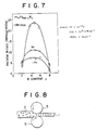
- Fig. 7 showing respectively the relation between Pr content and magnetic characteristics and that of B content and magnetic properties of respective magnets
- Fig. 8 is a diagramatic view of the roll working
- Fig. 9 is a variation schematic view of extrusion
- Fig. 10 shows the variation in weight between a magnet according to the invention and a traditional one.
- the inventors achieved this invention after the evaluation of many kinds of cast alloys of R-Fe-B series and acquired the knowledge that when an appropriate heat treatment is applied to the alloy of Pr-Fe-B series high coercive force can be obtained and further, basing on this alloy, the investigation is made to the mechanical alignment by means of hot-pressing and to the improvement of the magnetic characteristics of the alloy with the additional element.
- the manufacturing method of permanent magnet in which said magnet being comprised alloy of R-M-X series, in which said R being at least one element selected from the group consisting of Pr, Nd, Dy, Ce, La, Y and Tb, said M being at least one element selected from the group consisting of Fe, Co, Cu, Ag, Au, Ni and Zr, and said X being at least one element selected from the group consisting of B, Ga and Al, the manufacturing process is characterised that melting and casting said alloy, hot-working said cast alloy at the temperature above 500°C to concentrate magnetic phase by removing or eliminating non magnetic R-rich phase and giving magnetic anisotropy by mechanical alignment.
- the process described above which comprises casting hot-working heat-treatment and does not include powder process, it is able to provide excellent magnet comparable to that obtained by the traditional manufacturing method.
- a permanent magnet manufactured according to this invention is provided by the process (a) ⁇ (c) shown in Fig. 2 which will be described later in the description of the embodiment.
- composition adjustment is made to embody stoichiometric R 2 Fe 14 B (in atomic percentage) or R 11.7 Fe 82.4 B 5.9 (in atomic percentage), but when R is rich, R-rich phase may be affected as a non-magnetic phase and also when B is rich, B-rich phase acts as a non-magnetic phase.
- R contents are prepared little greater than the stoichiometric content so the R-rich phase can be considered as a non-magnetic phase, but when B content little greater than the stoichiometric content, obviously B-rich phase may be considered to be a non-magnetic phase.
- crystal grain size is limited in the range between 0.3 ⁇ 150 ⁇ m, the reason for which is as described below:
- Crystal grain size of 0.3 micrometer is said to be the critical radius of the single magnetic domain particle and when the particle size becomes smaller than 0.3 ⁇ m, initial magnetising curve becomes equal to that of the permanent magnet (3) of the traditional manufacturing method described hereinbefore.
- crystal grain size exceeds 150 ⁇ m, provided magnet has coercive force lower than that of ferrite magnet of 10 7 / ⁇ Am -1 (4KOe), after the hot-working and becomes practically useless. From these reasons crystal grain size range is limited between 0.3 and 150 ⁇ m.
- Ms (4 ⁇ Is) solid line
- Ms (4 ⁇ Is) increases when non-magnetic R-rich phase content is lowered.
- Ms (4 ⁇ Is) decreases, so that it must be kept below 10% after the consideration of practical application. But if it becomes 0%, it loses coercive force, therefore, it may be limited between beyond 0% and 10%.
- FIG. 1 A process chart of the manufacturing method according to the invention is shown in Fig. 1.
- mainly hot-pressing was carried out at a temperature of 1000°C to align crystal grain of the alloy.
- For the hot-pressing is controlled to minimize strain rate.
- C-axes of the crystal grain are aligned to be parallel to the compression direction of alloy at elevated temperature region.
- alloy comprising Pr 17 Fe 76.5 B 5 Cul. 5 was melted in the induction furnace having argon atmosphere and cast.
- the purity of rare-earth, iron and copper, used was over 99.9% and for boron, ferroboron is used.
- the cast ingot is hot-pressed in an argon atmosphere at a temperature of 1000°C and at the thickness reduction of 80% as shown in Fig. 2.
- Compressing pressure in this process had a value between 0.2 and 0.8 ton/cm 2 and strain rate was a value between 10 -3 and 10 -4 /sec.
- the magnet produced by using the invention is not inferior to the conventional permanent magnet (1) and (3) in the magnetic property and is superior in the magnetizing property.
- the permanent magnet according to the invention differs from the sintered permanent magnets (1) in Oxygen and Carbon content and in porosity, and differs from the permanent magnet (2) at the grain size of the crystal, and is superior in the magnetization.
- Fig. 2 shows the function of the invention.
- Fig. 2 11 shows Pr 2 Fe 14 B phase particle, 12 shows ⁇ -Fe phase, 13 R-rich phase, and 14 R-rich liquid phase.
- the permanent magnet in accordance with the invention is manufactured by the process shown in Fig. 2.
- Fig. 2(a) shows condition of main phases after melting and casting an alloy comprising Pr 17 Fe 76.5 B 5 Cu 1.5 , and as shown in the figure, small amount of ⁇ -Fe phase 12 is included within the Pr 2 Fe 14 B phase grain 11.
- Fig. 2(b) shows a condition in the hot-pressing, and in the temperature of 800 ⁇ 1050°C, R-rich phase 13 is melted and changed into R-rich liquid phase 14, changed R-rich liquid phase 14 is removed by the pressure applied through hot-working such as hot-pressing and squeezed out to the outside.
- ⁇ - Fe phase 12 is diffused and eliminated, and Pr 2 Fe 14 B phase grain 11 is pulverised during hot-press working and also crystal alignment along C-axis is directed to the compression direction.
- Fig. 2(c) shows a condition of the magnet, in which a squeezed out R-rich phase 13 portion is cut away and central portion in which fine Pr 2 Fe 14 B phase particle 11 is used as a magnet.
- a space among each Pr 2 Fe 14 B phase grain is filled with R-rich phase 13, iron and copper. It is obvious that the quantity of the filling material is much reduced compared with that the cast ingot and that the magnetic Pr 2 Fe 14 B phase grain is much concentrated compared with that of the initial ingot.
- Fig. 3 relation between content of R-rich phase of the magnet and M s (4 ⁇ Is) and iHc are shown. Also, in Fig. 4, M-H (4 ⁇ I-H) curves of the magnet comprised Pr 17 Fe 76.5 B 5 Cu 1.5 are shown and each respectively shows said curves pressed parallel and perpendicular to the pressing direction.
- Fig. 3 shows that M s (4 ⁇ Is) (solid line) increase when the quantity of non-magnetic R-rich phase decrease. Because that the M s (4 ⁇ Is) decreases when the quantity of R-rich phase increases, it is understandable that from the viewpoint of utility, it is desirable that the quantity thereof must be below 10%.
- Fig. 4 shows two kinds of demagnetizing curve of the typical hot-pressed Pr-Fe-B-Cu magnet measured in easy and hard magnetization direction.
- this magnet has a same direction of anisotropy but has a different coercive force mechanism compared with the conventional magnet of (3).
- An alloy comprising Pr 17 Fe 79 B 4 has melted by means of induction furnace in an argon atmosphere in accordance with the process shown in Fig. 1 and cast.
- Table 2 shows magnetic properties measured before and after the annealing, and in table 3 several magnetic property after the annealing is shown.
- magnetic phase is concentrated as shown in the difference between raw-material composition Pr 17 Fe 79 B 4 and magnet composition Pr 14.8 Fe 80.3 B 4.9 .
- the magnetic properties have shown excellent values and more particularly, as shown in table 2 and Fig. 5, it is obvious that the magnetic properties can be enhanced by means of annealing.
- Fig. 6 and Fig. 7 shows composition dependency of the hot-pressed magnet, in which all the measurement has done in the orientation which is parallel to that of the pressing. Also, it is easily understandable that the magnet is anisotropic because the value (BH) max KJm -3 (MGOe) is greatly enhanced.
- the cast ingot was hot-pressed at the temperature of 1000°C at the strain rate of 10 -3 -10 -4 /sec. with thickness reduction of 80% as shown in Fig. 2.
- the cast ingot has worked by using the working methods such as hot-pressing rolling and extruding respectively at a temperature of between 900 and 1000 o C as shown in Table 8.
- Fig. 8 and Fig. 9 show illustrations of the hot-rolling and extrusion.
- FIG. 5 illustrates roll, 6 hydraulic press and 7 dies respectively.
- stamp 3 and roll 5 are adjusted, to give least strain rate. Also, in each processes they are controlled respectively to give easily magnetization axis of the crystal grain may be aligned parallel to the compression direction of the alloy in a high temperature region as seen by allows in the figures.
- the magnet provided with the method described in embodiment 1 in accordance with the invention and the conventional sintered magnet are provided with the same composition (Nd 15 Fe 77 B 5 ) and the same form and are introduced into the thermohygrostat kept at 40°C and 95 % relative humidity and checked a weight change. Results are shown in Fig. 10.
- the magnet manufactured in accordance with the invention has a less weight change and indicated that it has less oxygen concentration. This is a far great difference between two kind of magnets.
- the permanent magnet having essential ingredients comprising R, M and X in which said R being at least one rare earth element selected from the group consisting of Pr, Nd, Dy, Ce, La, Y and Tb, said M being at least one transition element selected from the group consisting of Fe, Co, Cu, Ag, Ni, Au and Zr and said X being at least one IIIa element of the periodic table selected from the group consisting of B,Ga and Al has a high coercive force and can be developed anisotropic property by means of hot working such as hot-pressing, and its maximum (BH) max value reaches the value of approximately 348.9KJm -3 (43.6 MGOe).
- R being at least one rare earth element selected from the group consisting of Pr, Nd, Dy, Ce, La, Y and Tb
- said M being at least one transition element selected from the group consisting of Fe, Co, Cu, Ag, Ni, Au and Zr
- said X being at least one IIIa element of the periodic table selected from the group consisting of B,
Landscapes
- Engineering & Computer Science (AREA)
- Power Engineering (AREA)
- Chemical & Material Sciences (AREA)
- Crystallography & Structural Chemistry (AREA)
- Inorganic Chemistry (AREA)
- Manufacturing & Machinery (AREA)
- Hard Magnetic Materials (AREA)
- Manufacturing Cores, Coils, And Magnets (AREA)
Abstract
Description
- This invention generally relates to a method of manufacturing a permanent magnet of magnetic anisotropy by means of mechanical orientation, and more particularly to a method of manufacturing a permanent magnet comprising R [at least one element selected from the group consisting of rare earth elements including Yttrium(Y)], M(at least one element selected from the group consisting of transition elements) and X(at least one element selected from the group consisting of IIIa elements of the periodic table).
- Permanent magnet is one of the important electric-electronic material used in a wide field such as that from many kinds of domestic appliance to peripheral equipments of a large scale computer, and, in consequent with the present user's request of minaturization and the improvement of efficiency of these apparatus, higher performance permanent magnet have been required.
- Permanent magnet is a material which can produce magnetic field without applying electric power and magnetic material having high coercive force and high residual magnetic flux density is suitable in use. These requirements are quite different from high permeability magnetic material, which is used at present, there are cast magnets of Alnico series, barium-ferrite magnet and a magnet of rare-earth transition metal series.
- Particularly, permanent magnets of rare-earth transition metal magnet series such as R-Co series of R-Fe-B series have high magnetic properties having very high coercive force and energy-product value, therefore, much research and development have been carried out.
- The following are several references for the high performance anisotropic permanent magnets of the rare-earth-iron (transition metal) series and their manufacturing method;
(1) First of all, in the specification of Japanese patent application disclosure No. 59-46008 (equivalent to EP 101552A and USP 4770723) and in the reference of M. Sagawa, S. Fujimura, N. Togawa, H. Yamamoto and Y. Matsuura (J. Appl Phys Vol.55(6) 15 March 1984 p.2083) disclose permanent magnet characterized of magnetically anisotropic sintered substance comprised of 8-30 atomic % of R(R being at least one element selected from the group consisting of rare-earth element including Y) and residual of iron(Fe) and this substance is manufactured by means of sintering method of powder metallurgy. - In this sintering method, the manufacturing process is comprised of preparing alloy ingot by means of melting and casting, providing magnetic powder of suitable grain size by means of grinding, blending said powder with an additive binder for forming and forming green body by press-forming in a magnetic field. After pressing the green body is sintered in the argon atmosphere at a temperature of 1100 degree centigrade for about one hour and after that, product is rapidly cooled to a room temperature. After the sintering, product is heat-treated at 600 degree centigrade to improve coercive force.
(2) Also, relevant the specification of Japanese patent application disclosure No. 59-211549 (equivalent to EP125752) and reference by R.W. Lee; (Appl. Phys. Lett. vol. 46(8) 15 Apr. 1985 p790). - In these references, there are disclosed a resin-bonded rare-earth-iron magnet, which is formed from fine particles of alloy ribbon prepared by means of melt-spinning method and having fine crystalline magnetic phase and in which said alloy being comprised at least one rare earth element selected from the group consisting of neodymium, praseodymium and misch metal, transition metal element, iron and boron, characterising that said fine particles being formed in the desired shape of magnet by a binder mixed with said particles, said fine particle being magnetically isotropic, said formed magnet being magnetised to any desired direction in a proper magnetic field, said magnet having density of at least 80% of the alloy density and having energy product of at least 9 megagauss-oersted (approx. 72KJm-3).
- This permanent magnet is manufactured by means of resin-bonding method using rapidly quenched thin ribbon prepared by melt spinning method having process comprising providing rapidly quenched thin ribbon of about 30 micrometer thickness by means of melt spinning apparatus used to provide amorphous alloy.
- In the resin bonding method using rapid-quenched ribbon prepared by the melt-spinning method, at first rapid-quenched thin ribbon of R-Fe-B alloy is prepared by means of melt spinning apparatus. The obtained ribbon of 30 micrometer thickness thus provided is an aggregate of crystal of diameter less than 1000 micrometer, and is brittle and easily breakable and the crystals are distributed homogeneously therefore it has an isotropic magnetic property. It is able to obtain a magnet having a density of more than 85 % of the ribbon density by means of press forming pulverised particles obtained by pulverising the thin ribbon to a desired grain size with a resin under a pressure of about 7 ton/cm2.
(3) Further, the Japanese patent application disclosure no. 60-100402 (equivalent to EP 133758A) and R.W. Lee; Appl. Phys. Letter. Vol. 46(8), 15 April 1985, p790. describe; - (a) Isotropic permanent magnet comprised fully densified fine particles characterised in that the magnet being provided by hot pressing amorphous or fine particle material comprising iron, neodimium and/or praseodymium and boron.
- (b) Anisotropic permanent magnet consists of fine particles characterised in providing magnet by hot pressing and hot die upsetting a material comprising iron, neodimium and/or praseodymium and boron, desirable magnetising direction of thus provided magnet being parallel to the upset compression direction.
- (c) Permanent magnet characterising said magnet being formed by high temperature plastic deforming amorphous or fine particle alloy comprising substantially 50∼90 atomic % of iron, 10∼50 atomic % of neodymium and/or praseodymium and 1∼10 atomic % of boron in which desirable magnetizing direction being perpendicular to the plastic flow in said deformation.
- Also, for the production method:
- A manufacturing method of a permanent magnet, said permanent magnet being anisotropic characterizing that said permanent magnet being composes of iron-rare-earth metal, and its manufacturing method comprising heat treating amorphous or fine grained solid particles including iron, neodymium and/or praseodymium and boron to prepare plastically deformed body of fine grained microstructure, cooling said body to prepare the body having anisotropic magnetic property and showing permanent magnet property.
- The manufacturing method of these magnet is a method to manufacture R-Fe-B magnet having anisotropic property and having high density by means of 2-step hot-pressing method in a vacuum or inert-gas atmosphere from a ribbon-like rapidly quenched thin ribbon or plate.
- In this pressing process, one-axial pressure is applied to align easy magnetization direction parallel to said pressing axis to prepare anisotropically magnetizable alloy.
- Also, it is preferable that particle grain size of said ribbon-like thin plate manufactured preliminary by melt-spinning method may be prepared smaller than the grain size showing maximum coercive force to give optimum grain size after the grain-growth in the hot-press process.
- (4) Finally, Japanese patent application disclosure No. 62-276803 (equivalent to DE3626406A or U.S. Patent application No. 06/895653) discloses a permanent magnet of rare-earth-iron system which is characterized by melting an alloy comprising 8∼30 atomic % of R (at least one element selected from the group consisting of rare-earth including Y), 2∼28 atomic % of boron, less than 50 atomic % of cobalt, less than 15 atomic % of aluminium and rest iron and inevitable inpurities, casting said alloy, hot-working at a temperature above 500°C said cast ingot to refine crystal grain and also to orient crystal axis to a specific direction to make magnetic anisotropy said cast alloy.
- The permanent magnet of R-Fe-B system described above is (1) to (4) have drawbacks described below:
- The manufacturing method described in the references (1), which is indispensable to pulverize alloy, and because of that the R-Fe-B alloy is very active to oxygen, and when it is pulverized, the power is terribly oxidized becomes high.
- Also, in the process of the formation of the powder, it is necessary to add forming additive such as zinc stearate, although this additive may be removed preliminarily before the sintering process, some part of the additive remains in the magnet body in the form of carbon, and it is not desirable because this residual carbon deteriorates magnetic property of the R-Fe-B magnet.
- Formed body, which is called green body, is very difficult to handle because it is easy to break. Thus, the handling is very troublesome when the formed bodies are arranged regularly in the sintering furnace.
- Because of these defects, generally speaking, to manufacture magnet of R-Fe-B series, manufacturing cost of these magnets become ultimately expensive, because it is not only necessary to provide expensive equipment but also the manufacturing method thereof has least productivity. Thus, it is not able to utilize effectively a merit of the R-Fe-B series magnet of relatively cheap raw materials.
- Permanent magnets in accordance to references (2) and (3) are manufactured by means of vacuum-melt spinning machine, this machine is not only very expensive but also have very low productivity at least at present.
- Permanent magnet in accordance to the reference (2) is disadvantageous not only in the temperature characteristics but also for the application thereof because it has homogeneous magnetic property so that it has low energy product and also has bad squareness of the hysteresis loop.
- The manufacturing method in accordance with reference (3) is a unique one which utilizes hot-pressing in two-steps, but when considered for use in mass-production, it is inefficient.
- Further, in this process, coarsening of the crystal grains is remarkable if the temperature rises above 800°C. Because of which intrinsic coercive force iHc becomes extremely low, so it is not possible to provide a practical permanent magnet.
- The method of manufacturing a permanent magnet in accordance with the reference (4), has a problem that the manufactured magnet has somewhat inferior magnetic properties compared with that of the magnet according to references (2) or (3): although it does not include a pulverising process and has only one hot-press process thus reducing the manufacturing process to its maximum extent.
- Also known is European Patent Publication No. 0231620, which describes a method of making a permanent magnet of composition Nd16.5Fe76.3B7.2 by chilling the molten alloy, breaking it up into particles and then hot working the particles in order to gain magnetic anisotropy by means of mechanical alignment. The substitution of Pr for Nd and Co for some of the Fe is suggested.
- This invention is to solve disadvantages in the traditional techniques hereinabove described, in particular, in the characteristics of the permanent magnet in accordance with the reference (4), and the object thereof is to provide an inexpensive permanent magnet but which has excellent characteristics and the manufacturing method thereof.
- Thus, according to the present invention, there is provided a method of manufacturing a permanent magnet comprising melting and casting an alloy having a composition comprising R, R being at least one element selected from the group consisting of rare-earth elements including Y, M, M being at least one element selected from the group consisting of transition metal elements and X, X being at least one element selected from the group consisting of IIIa group of the periodic table, heating and compressing said cast alloy at a temperature of 500°C or above characterised by said heating and compressing squeezing the non-magnetic R-rich phase to the outside edges of the alloy and by removal of at least part of the thus squeezed out R-rich phase whereby the volume fraction of the magnetic phase is raised and magnetic anisotropy is gained by means of mechanical alignment.
- Preferably the alloy used in the method according to the invention is comprised of 12 ∼25 atomic % of R, 65∼85 atomic % of M and 3∼10 atomic % of X.
- Also the manufacturing method of aforesaid permanent magnet is characterised in that melting and casting alloy of said basic component, then hot-working at a temperature above 500°C to reduce or eliminate non-magnetic R-rich liquid phase and to concentrate magnetic phase comprising 10-18 atomic % of R, 72∼87 atomic % of M and 3∼10 atomic % of X and giving magnetic anisotropy by means of mechanical alignment.
- Also the object of the invention is to provide said permanent magnet having a crystal grain size of 0.3∼150µm and having a concentration of less than 10% (not including 0%) of said R-rich phase.
- Also, the manufacturing method thereof is characterised by melting and casting said basic raw materials, hot working said cast ingot at a temperature above 500°C to reduce or eliminate non-magnetic R-rich phase to concentrate the magnetic phase comprising 10-18 atomic % of Pr, 72∼87 atomic % of Fe and 3∼10 atomic % of B, to provide an anisotropic permanent magnet by means of mechanical alignment and having a grain size of 0.3∼150µm and the ratio of said R-rich phase of less than 10% (not included 0%).
- Further, it is a manufacturing method of the permanent magnet described above, in which after the hot-working of the cast ingot, the material is heat-treated and also, one of the hot working being selected from the group consisting hot-press, hot rolling and extrusion is performed.
- Method of manufacturing a permanent magnet according to this invention is effective as described below:
- (1) It is able to raise crystal alignment along C-axis to substantially improve residual magnetic flux density Br, and also by refining particle size of the crystal coercive force and maximum energy product (BH) max can be substantially raised.
- (2) Manufacturing cost is inexpensive because of simple manufacturing process.
- (3) It is able to improve corrosion resistance because said magnet is less active to the oxygen owing to the low concentration of oxygen in the magnet body.
- (4) Manufacturing cost can be reduced because of a good machinability thereof.
- (5) Number of working steps and amount of investment can be substantially reduced compared with the conventional sintering manufacturing method.
- (6) Low-cost magnet with excellent performance can be provided compared with the manufacturing method of magnet of conventional melt-spinning method.
- Fig. 1 is a manufacturing process chart of the magnet of R-Fe-B series according to the invention, Fig. 2 is a schematic illustration showing an effect of this invention, Fig. 3 is a graph showing relation between contention of R-rich phase and Ms (4πIs) and iHc, Fig. 4 is a diagram showing two M-H (4πI-H) curve of the magnet manufactured according to the invention and each curve showing respectively a curve of two orientation one of which is parallel to the compression direction and other perpendicular thereof after hot-pressing process, Fig. 5 is demagnetizing curves of cast ingot showing respectively before and after annealing, Fig. 6 and Fig. 7 showing respectively the relation between Pr content and magnetic characteristics and that of B content and magnetic properties of respective magnets, Fig. 8 is a diagramatic view of the roll working, Fig. 9 is a variation schematic view of extrusion and Fig. 10 shows the variation in weight between a magnet according to the invention and a traditional one.
- The inventors achieved this invention after the evaluation of many kinds of cast alloys of R-Fe-B series and acquired the knowledge that when an appropriate heat treatment is applied to the alloy of Pr-Fe-B series high coercive force can be obtained and further, basing on this alloy, the investigation is made to the mechanical alignment by means of hot-pressing and to the improvement of the magnetic characteristics of the alloy with the additional element.
- Thus, in accordance with the invention, the manufacturing method of permanent magnet is provided in which said magnet being comprised alloy of R-M-X series, in which said R being at least one element selected from the group consisting of Pr, Nd, Dy, Ce, La, Y and Tb, said M being at least one element selected from the group consisting of Fe, Co, Cu, Ag, Au, Ni and Zr, and said X being at least one element selected from the group consisting of B, Ga and Al, the manufacturing process is characterised that melting and casting said alloy, hot-working said cast alloy at the temperature above 500°C to concentrate magnetic phase by removing or eliminating non magnetic R-rich phase and giving magnetic anisotropy by mechanical alignment. In accordance with the process described above, which comprises casting hot-working heat-treatment and does not include powder process, it is able to provide excellent magnet comparable to that obtained by the traditional manufacturing method.
- In accordance with the invention, a permanent magnet manufactured according to this invention is provided by the process (a) ∼ (c) shown in Fig. 2 which will be described later in the description of the embodiment.
- As a result of squeezing out the non-magnetic R-rich liquid phase from the initial R-M-X basic material by hot-working such as hot-pressing, carried out at a temperature above 500°C preferably at 750 ∼ 1050°C, ferromagnetic particles are concentrated and only the particle phase is refined and aligned, enforcement of the magnetic properties are provided.
- In the manufacturing of the magnet, composition adjustment is made to embody stoichiometric R2Fe14B (in atomic percentage) or R11.7Fe82.4B5.9 (in atomic percentage), but when R is rich, R-rich phase may be affected as a non-magnetic phase and also when B is rich, B-rich phase acts as a non-magnetic phase.
- In this invention, R contents are prepared little greater than the stoichiometric content so the R-rich phase can be considered as a non-magnetic phase, but when B content little greater than the stoichiometric content, obviously B-rich phase may be considered to be a non-magnetic phase.
- Followings are the reason for the composition limit of the basic component R, M and X of the raw material:
- When it becomes below 12%, quantity of R-rich phase becomes too small and makes hot-working difficult. Also, when it exceeds 25%, quantity of non-magnetic phase becomes too much and results in poor concentration of magnetic phase and also affects to the properties. From these reason, R content is limited as shown above.
- When it exceeds 85%, R-rich phase becomes smaller and causes hot-working difficult. Also, when it becomes below 65%, quantity of non-magnetic phase becomes too much and results in poor concentration of magnetic phase and also affects to the performance. From these reason, M content is limited as shown above.
- When it becomes below 3% quantity of magnetic phase becomes too small and cannot provide high performance. Also, when it exceed 10% non-magnetic phase becomes too much and also hot working becomes difficult. From these reason, X contents are limited as shown above.
- Basic composition of raw material specified as above, gives product composition after the application of the hot working of R: 10 ∼ 18%, M: 72 ∼ 87%, X: 3 ∼ 10% which are the composition range which provides excellent magnetic properties in accordance with the invention.
- Further, in accordance with the invention, crystal grain size is limited in the range between 0.3 ∼ 150 µm, the reason for which is as described below:
- Crystal grain size of 0.3 micrometer is said to be the critical radius of the single magnetic domain particle and when the particle size becomes smaller than 0.3 µm, initial magnetising curve becomes equal to that of the permanent magnet (3) of the traditional manufacturing method described hereinbefore.
- Also, when crystal grain size exceeds 150 µm, provided magnet has coercive force lower than that of ferrite magnet of 107/πAm-1 (4KOe), after the hot-working and becomes practically useless. From these reasons crystal grain size range is limited between 0.3 and 150 µm.
- Further, as will be shown later in Fig. 4, Ms (4πIs) (solid line) increases when non-magnetic R-rich phase content is lowered. Also, when R-rich phase contents increase, Ms (4πIs) decreases, so that it must be kept below 10% after the consideration of practical application. But if it becomes 0%, it loses coercive force, therefore, it may be limited between beyond 0% and 10%.
- In the following, several embodiment will be described.
- A process chart of the manufacturing method according to the invention is shown in Fig. 1.
- In this embodiment, for the hot working process, mainly hot-pressing was carried out at a temperature of 1000°C to align crystal grain of the alloy. For the hot-pressing is controlled to minimize strain rate. Also, C-axes of the crystal grain are aligned to be parallel to the compression direction of alloy at elevated temperature region.
- At first, following to the manufacturing process shown in Fig. 1, alloy comprising Pr17Fe76.5B5Cul.5 was melted in the induction furnace having argon atmosphere and cast.
- The purity of rare-earth, iron and copper, used was over 99.9% and for boron, ferroboron is used.
- After then, the cast ingot is hot-pressed in an argon atmosphere at a temperature of 1000°C and at the thickness reduction of 80% as shown in Fig. 2. Compressing pressure in this process had a value between 0.2 and 0.8 ton/cm2 and strain rate was a value between 10-3 and 10-4/sec.
- After then, annealing for 24 hour was done at a temperature of 1000°C and then out and polished to measure magnetic property.
- Magnetic properties and other properties of this magnet are shown in table 1 with some reference data showing values obtained from sintered permanent magnet (Nd15Fe77B8) of traditional method described in (1) and (Nd13Fe82.6B4.4) of (3).
- Further, magnetic properties were measured by the B-H tracer of maximum applied magnetic field of 2.5 x 10⁸/4πAm-1 (25K0e).
Table 1 invented magnet (embodiment 1) conventional magnet (1) conventional magnet (3) raw mat'L Pr17FE76.5B5Cu1.5 Nd15Fe77B8 Nd13Fe82.6B4.4 magnet composition Pr13.5Fe79.6B6.3Cu0.9 same above same above Br(KG) 12.5 12.5 11.75 iHc(kOe) 9.9 13.8 13.0 BHmax(MGOe) 36.2 37.7 32.0 Avg.grain size 22 20 ∼0.02 02(ppm) 210 2900 900 C(ppm) 200 820 1000 porosity 0.2 2.7 0.2 R-rich phase ratio(%) 5.2 8.1 3.8 magnetization good good bad where; 1G = 10-4 T 10e = 104/4πAm-1 1MGOe = 8KJm-3 - As shown in table 1, it is obvious that the magnet produced by using the invention is not inferior to the conventional permanent magnet (1) and (3) in the magnetic property and is superior in the magnetizing property.
- Further, to add copper for cast magnet is very effective to improve coercive force and it shows it is also effective to the improvement of the magnetic alignment.
- The permanent magnet according to the invention differs from the sintered permanent magnets (1) in Oxygen and Carbon content and in porosity, and differs from the permanent magnet (2) at the grain size of the crystal, and is superior in the magnetization.
- Structural mechanism of the magnet according to this invention will be described in the following.
- Fig. 2 shows the function of the invention.
- In Fig. 2, 11 shows Pr2Fe14B phase particle, 12 shows α-Fe phase, 13 R-rich phase, and 14 R-rich liquid phase.
- In accordance with the invention, the permanent magnet in accordance with the invention is manufactured by the process shown in Fig. 2.
- Fig. 2(a) shows condition of main phases after melting and casting an alloy comprising Pr17Fe76.5B5Cu1.5, and as shown in the figure, small amount of α-
Fe phase 12 is included within the Pr2Fe14B phase grain 11. - Also, among said Pr2Fe14
B phase grain 11, non-magnetic R-rich phase is filled. - Fig. 2(b) shows a condition in the hot-pressing, and in the temperature of 800 ∼ 1050°C, R-
rich phase 13 is melted and changed into R-richliquid phase 14, changed R-richliquid phase 14 is removed by the pressure applied through hot-working such as hot-pressing and squeezed out to the outside. - Also, α -
Fe phase 12 is diffused and eliminated, and Pr2Fe14B phase grain 11 is pulverised during hot-press working and also crystal alignment along C-axis is directed to the compression direction. - Fig. 2(c) shows a condition of the magnet, in which a squeezed out R-
rich phase 13 portion is cut away and central portion in which fine Pr2Fe14B phase particle 11 is used as a magnet. - A space among each Pr2Fe14B phase grain is filled with R-
rich phase 13, iron and copper. It is obvious that the quantity of the filling material is much reduced compared with that the cast ingot and that the magnetic Pr2Fe14B phase grain is much concentrated compared with that of the initial ingot. - In Fig. 3, relation between content of R-rich phase of the magnet and Ms(4πIs) and iHc are shown. Also, in Fig. 4, M-H (4πI-H) curves of the magnet comprised Pr17Fe76.5B5Cu1.5 are shown and each respectively shows said curves pressed parallel and perpendicular to the pressing direction.
- Fig. 3 shows that Ms(4πIs) (solid line) increase when the quantity of non-magnetic R-rich phase decrease. Because that the Ms(4πIs) decreases when the quantity of R-rich phase increases, it is understandable that from the viewpoint of utility, it is desirable that the quantity thereof must be below 10%.
- Fig. 4 shows two kinds of demagnetizing curve of the typical hot-pressed Pr-Fe-B-Cu magnet measured in easy and hard magnetization direction.
- From Fig. 4, it can be seen that the easy magnetization direction is parallel to the compression direction. From the initial magnetizing curve, it may be concerned that this magnet has a nucleation type coercive force mechanism.
- It may be realized that this magnet has a same direction of anisotropy but has a different coercive force mechanism compared with the conventional magnet of (3).
- An alloy comprising Pr17Fe79B4 has melted by means of induction furnace in an argon atmosphere in accordance with the process shown in Fig. 1 and cast.
- In this time purity iron and rare-earth used was over 99.9% and for the boron, ferroboron was used.
- Then, the cast ingot was hot pressed in the argon atmosphere in order to make 80% thickness reduction as shown in Fig. 2. Compression pressure in this work has 0.2∼0.8 ton/cm2 and strain rate was 10-3 -10-4/sec.
- After these treatment, magnetic properties were measured and after annealing of 1000oC 24 hour, magnetic properties were measured again.
- Table 2 shows magnetic properties measured before and after the annealing, and in table 3 several magnetic property after the annealing is shown.
- Further, in Fig. 5, demagnetizing curve (1) of cast ingot and that of the magnet after annealing is shown.
Table 2 Br (KG) iHc (KOe) (BH) max (MGOe) before anneal 10.6 3.6 14.3 after anneal 10.8 7.3 22.2 where; 1G = 10-4 T 10e = 104/4πAm-1 1MGOe = 8KJm-3Table 3 Low material composition Pr17Fe79B4 magnet composition Pr14.8Fe80.3B4.9 avg. particle size 20 oxygen O (ppm) 250 carbon C (ppm) 180 porosity (%) 0.2 R-rich phase ratio (%) 7.9 magnetization good - As shown in Table 3, magnetic phase is concentrated as shown in the difference between raw-material composition Pr17Fe79B4 and magnet composition Pr14.8Fe80.3B4.9. Also, the magnetic properties have shown excellent values and more particularly, as shown in table 2 and Fig. 5, it is obvious that the magnetic properties can be enhanced by means of annealing.
- Further, when cast ingot is prepared with same manufacturing condition but with changed quantities of Pr and/or B, properties of the magnet produced is changed as shown in Fig. 6 and Fig. 7.
- Fig. 6 and Fig. 7 shows composition dependency of the hot-pressed magnet, in which all the measurement has done in the orientation which is parallel to that of the pressing. Also, it is easily understandable that the magnet is anisotropic because the value (BH) max KJm-3(MGOe) is greatly enhanced.
- Alloy having composition of Pr2Nd5Fe79B5.5Cu1.5 was melted and cast to provide case ingot by means of the process described in Embodiments (1) and (2).
- After that, the cast ingot was hot-pressed at the temperature of 1000°C at the strain rate of 10-3 -10-4/sec. with thickness reduction of 80% as shown in Fig. 2.
- After 1000°C 24 hours annealing, alloy has cut and polished and magnetic property of the magnet produced of composition of Pr9.5Nd4Fe80.1B6.1Cu0.8 was measured.
- Magnetic and other properties of the magnet is tabulated in the Table 4.
- As tabulated in the Table, it is obvious that magnetic properties thereof is excellent regardless of variation of the composition shown below.
Table 4 Composition of raw material Pr12Nd5Fe79B5.5Cu1.5 Composition of magnet Pr9.5Nd4Fe80.1B6.1Cu0.3 Br (KG) 12.5 iHc (KOe) 8.8 (BH) max (MGOe) 33.1 Oxygen O (ppm) 230 Carbon C (ppm) 190 Porosity (%) 0.2 R-rich phase ratio (%) 5.1 avg. particle size (µm) 24 magnetizing good where; 1G = 10-4 T 10e = 104/4πAm-1 1MGOe = 8KJm-3 - Alloys as shown in Table 5 were melted and cast in the same way as
Embodiment 1∼3. Provided material were same as shown above. - Then, these cast ingots were hot-pressed in the argon atmosphere as shown in Fig. 2 and annealed. After cutting and polishing, magnetic properties were measured. Compositions of magnets in Table 6 and several magnetic properties in Table 7 are shown respectively.
Table 5 Alloy Composition No. 1 Pr15Fe80B5 2 Pr10Fe75.5B5.5 3 Pr22Fe72B6 4 Pr10Nd7Fe75Co4B4 5 Pr5Nd14Fe67Co8B5Cu1 6 Pr8Nd8Fe71Co5B5.5Cu5Ga1 7 Pr10Nd5Dy3Fe75B5Cu2 8 Ce2Pr15Nd2Fe50Co25B4Cu1Ga1 9 Pr16Nd2Fe74B5Cu1Ga1Al1 10 Pr15Nd5Fe61CO10B7Ag2 11 Ce3Pr10Nd4Fe77B4Ni1Zr1 12 La1Pr17Fe70Co3B6Cu3 13 Dy5Nd11Fe77B5.5Cu2 14 Pr14Tb3.5Fe71CO5B5.5Au1 15 Nd17Fe75.5B5Ag1.5Ga1 Table 6 Composition of Magnet No. 1 Pr13.5Fe80.2B5.8 2 Pr14Fe80.2B5.8 3 Pr14.3Fe79.5B6.2 4 Pr7.6Nd5.5Fe76.9Co5B5 5 Pr3.6Nd10.5Fe71Co9B5.7Cu0.2 6 Pr6Nd6.7Fe74.9Co6B6Cu0.3Ga0.1 7 Pr7Nd3.5Dy2Fe81.4B5.8Cu0.3 8 Ce1.5Pr10.1Nd1.4Fe55.1Co26.5B5.1Cu0.2Ga0.1 9 Pr11.2Nd1.4Fe80.8B5.9Cu0.2Ga0.1A10.4 10 Pr10.5Nd3.4Fe67Co11.5B7.2Ag0.4 11 Ce2.1Pr8/2Nd3.3Fe80.3B5.2Ni0.4Zr0.6 12 La0.7Pr11.7Fe77.4Co3.5B6.3Cu0.4 13 Dy4.2Nd9.2Fe80.8B5.5Cu0.3 14 Pr9.8Tb3Fe75.5Co5.5B6Au0.2 15 Nd13.2Fe80.6B5.7Ag0.3Ga0.2 Table 7 Br(KG) iHc (KOe) (BH)max(MGOe) avg.gr.size(µm) R-rich phase (%) 1 12.0 7.9 29.2 -25 4.1 2 12.3 9.6 32.7 27 5.7 3 11.2 12.2 28.3 20 6.5 4 10.8 11.8 26.3 23 3.7 5 13.0 10.5 38.1 24 6.1 6 13.6 15.0 41.7 18 3.0 7 13.4 13.6 40.5 20 2.8 8 11.9 12.5 31.9 20 3.8 9 12.9 14.3 37.5 21 3.7 10 12.7 6.6 29.1 30 5.9 11 12.6 12.2 35.8 20 5.8 12 13.3 10.8 39.9 17 2.8 13 13.5 14.6 42.0 15 4.6 14 13.9 16.6 42.5 20 2.7 15 14.0 8.8 37.7 25 4.5 where; 1G = 10-4T 10e = 104/4πAm-1 1MGOe = 8KJm-3 - An alloy having composition of Pr15Nd2Fe76.5B5Cu1.5 was melted and cast employing same raw materials described in the
embodiment 1∼4. - Then, the cast ingot has worked by using the working methods such as hot-pressing rolling and extruding respectively at a temperature of between 900 and 1000oC as shown in Table 8.
- Further, Fig. 8 and Fig. 9 show illustrations of the hot-rolling and extrusion. In these figures 5 illustrates roll, 6 hydraulic press and 7 dies respectively.
- In the meantime, for the hot-pressing and hot rolling of (a) and (b) respectively,
stamp 3 androll 5 are adjusted, to give least strain rate. Also, in each processes they are controlled respectively to give easily magnetization axis of the crystal grain may be aligned parallel to the compression direction of the alloy in a high temperature region as seen by allows in the figures. - After that annealing at 1000oC for 24 hours is carried out and then cut and polished to measure magnetic properties.
- In table 9 composition of the magnet and in table 10 the magnetic property of these magnet are shown respectively.
- As shown in Table 8∼10, magnetic properties are enhanced by all working process including hot-press, rolling and extrusion working.


Table 9 Magnet composition 16 Pr11.2Nd1.3Fe81.4B6 Cu0.1 17 Pr12.2Nd1.6Fe80 B5.8Cu0.4 18 Pr13.8Nd1.8Fe78.4B5.3Cu0.7 19 Pr14.9Nd2.0Fe76.7B5.0Cu0.9 20 Pr11,0Nd1.2Fe81.7B6.1Cu0.0 Table 10 Several Properties of Magnet(s) Br (KG) iHc (KOe) (BH) (MGOe) Avg. particle size (µm) R-rich phase (%) 16 13.9 12.2 43.6 21 2.4 17 11.4 12.7 29.3 22 5.0 18 10.9 14.7 26.8 17 6.5 19 9.8 16.6 21.2 13 10.1 20 11.9 8.8 28.6 27 5.6 where; 1G = 10-4 T 10e = 104/4πAm-1 1MGOe = 8KJm-3 - The magnet provided with the method described in
embodiment 1 in accordance with the invention and the conventional sintered magnet are provided with the same composition (Nd15Fe77B5) and the same form and are introduced into the thermohygrostat kept at 40°C and 95 % relative humidity and checked a weight change. Results are shown in Fig. 10. - As shown in Fig. 10, relative to the conventional magnet (sintered magnet), the magnet manufactured in accordance with the invention has a less weight change and indicated that it has less oxygen concentration. This is a far great difference between two kind of magnets.
- From these embodiments, it is obvious that the permanent magnet having essential ingredients comprising R, M and X in which said R being at least one rare earth element selected from the group consisting of Pr, Nd, Dy, Ce, La, Y and Tb, said M being at least one transition element selected from the group consisting of Fe, Co, Cu, Ag, Ni, Au and Zr and said X being at least one IIIa element of the periodic table selected from the group consisting of B,Ga and Al has a high coercive force and can be developed anisotropic property by means of hot working such as hot-pressing, and its maximum (BH) max value reaches the value of approximately 348.9KJm-3(43.6 MGOe).
Claims (8)
- A method of manufacturing a permanent magnet comprising melting and casting an alloy having a composition comprising R, R being at least one element selected from the group consisting of rare-earth elements including Y, M, M being at least one element selected from the group consisting of transition metal elements and X, X being at least one element selected from the group consisting of IIIa group of the periodic table, heating and compressing said cast alloy at a temperature above 500°C whereby the magnetic anisotropy is gained by means of mechanical alignment characterised by, said heating and compressing squeezing the non-magnetic R-rich phase to the outside edges of the alloy and by removal of at least part of the thus squeezed out R-rich phase whereby the volume fraction of the magnetic phase is raised.
- A method as claimed in claim 1, characterised in that R is Pr, Nd, Dy, Ce, La, Y and/or Tb, M is Fe, Co, Cu, Ag, Au, Ni, and/or Zr and X is B, Ga and/or Al.
- A manufacturing method as claimed in claim 1, characterised in that said alloy comprises 12∼25 atomic % of R, 65∼85 atomic % of M and 3∼10 atomic % of X; in that said cast alloy is hot worked at a temperature above 500°C to reduce liquid phase of non-magnetic R-rich phase and to condense a magnetic phase comprising 10∼18 atomic % of R, 72∼87 atomic % of M and 3∼10 atomic % of X and give magnetic anisotropy by means of mechanical alignment.
- A method as claimed in claim 3, characterised in that the initial composition comprises 12∼25 atomic % of Pr, 65∼85 atomic % of Fe and 3∼10 atomic % of B, and in that, following said hot-working at a temperature above 500°C the composition comprises a magnetic phase comprising 10∼18 atomic % of Pr, 72∼87 atomic % of Fe and 3∼10 atomic % of B, non-magnetic R-rich liquid phase having been removed from said cast ingot, and having a crystal grain size of between 0.3µm and 150µm and the volume fraction R-rich phase is less than or equal to 10%, but not including 0%, magnetic anisotropy being given by means of mechanical alignment.
- A method as claimed in claim 4, characterised in that said magnet also includes Cu.
- A method as claimed in any one of claims 1 to 5, characterised in that said hot-working is carried out at a temperature between 750°C and 1050°C.
- A method as claimed in any one of claims 1 to 6, characterised in that after the hot working, said cast alloy is heat treated.
- A method as claimed in any one of claims 1 to 7, characterised in that said hot working consists of hot-pressing, hot rolling or hot-extrusion.
Applications Claiming Priority (4)
| Application Number | Priority Date | Filing Date | Title |
|---|---|---|---|
| JP150039/88 | 1988-06-20 | ||
| JP150040/88 | 1988-06-20 | ||
| JP63150039A JPH023201A (en) | 1988-06-20 | 1988-06-20 | permanent magnet |
| JP63150040A JP2573865B2 (en) | 1988-06-20 | 1988-06-20 | Manufacturing method of permanent magnet |
Publications (3)
| Publication Number | Publication Date |
|---|---|
| EP0348038A2 EP0348038A2 (en) | 1989-12-27 |
| EP0348038A3 EP0348038A3 (en) | 1991-01-16 |
| EP0348038B1 true EP0348038B1 (en) | 1996-09-18 |
Family
ID=26479753
Family Applications (1)
| Application Number | Title | Priority Date | Filing Date |
|---|---|---|---|
| EP89305021A Expired - Lifetime EP0348038B1 (en) | 1988-06-20 | 1989-05-18 | Manufacturing method of a permanent magnet |
Country Status (6)
| Country | Link |
|---|---|
| US (1) | US5536334A (en) |
| EP (1) | EP0348038B1 (en) |
| KR (1) | KR910001826A (en) |
| AT (1) | ATE143171T1 (en) |
| DE (1) | DE68927203T2 (en) |
| IE (1) | IE891581A1 (en) |
Families Citing this family (10)
| Publication number | Priority date | Publication date | Assignee | Title |
|---|---|---|---|---|
| US5641363A (en) * | 1993-12-27 | 1997-06-24 | Tdk Corporation | Sintered magnet and method for making |
| EP0886284B1 (en) * | 1996-04-10 | 2002-10-23 | Showa Denko Kabushiki Kaisha | Cast alloy used for production of rare earth magnet and method for producing cast alloy and magnet |
| US5787912A (en) * | 1997-10-16 | 1998-08-04 | Wu; Tzun-Zong | Quickly foldable rib means of automatic umbrella |
| US6779426B1 (en) | 1999-12-21 | 2004-08-24 | Atlas Die Llc | Die rule retention device and retaining board incorporating same |
| AU2003291539A1 (en) * | 2002-11-18 | 2004-06-15 | Iowa State University Research Foundation, Inc. | Permanent magnet alloy with improved high temperature performance |
| RU2337975C2 (en) * | 2006-12-11 | 2008-11-10 | Дмитрий Валерьевич Гундеров | Method of constant magnet receiving from alloys on basis of system neodymium-iron-boron or praseodymium- iron-boron |
| CN103959412B (en) * | 2012-03-12 | 2018-03-30 | 日东电工株式会社 | Rare earth permanent magnet and method for producing rare earth permanent magnet |
| JP5960476B2 (en) * | 2012-03-30 | 2016-08-02 | 株式会社ケーヒン | Magnetic anisotropic plastic processed product, manufacturing method thereof, and electromagnetic device using the same |
| JP5752094B2 (en) * | 2012-08-08 | 2015-07-22 | ミネベア株式会社 | Method for producing full-dense rare earth-iron bond magnet |
| WO2016093379A1 (en) * | 2014-12-08 | 2016-06-16 | 엘지전자 주식회사 | Hot-pressed and deformed magnet comprising nonmagnetic alloy and method for manufacturing same |
Citations (1)
| Publication number | Priority date | Publication date | Assignee | Title |
|---|---|---|---|---|
| EP0231620A2 (en) * | 1986-01-29 | 1987-08-12 | General Motors Corporation | Permanent magnet manufacture from very low coercivity crystalline rare earth-transition metal-boron alloy |
Family Cites Families (15)
| Publication number | Priority date | Publication date | Assignee | Title |
|---|---|---|---|---|
| CA1316375C (en) * | 1982-08-21 | 1993-04-20 | Masato Sagawa | Magnetic materials and permanent magnets |
| CA1216623A (en) * | 1983-05-09 | 1987-01-13 | John J. Croat | Bonded rare earth-iron magnets |
| CA1236381A (en) * | 1983-08-04 | 1988-05-10 | Robert W. Lee | Iron-rare earth-boron permanent magnets by hot working |
| JPH0789521B2 (en) * | 1985-03-28 | 1995-09-27 | 株式会社東芝 | Rare earth iron permanent magnet |
| JPS6223959A (en) * | 1985-07-25 | 1987-01-31 | Sumitomo Special Metals Co Ltd | High-efficiency permanent magnet material |
| FR2586323B1 (en) * | 1985-08-13 | 1992-11-13 | Seiko Epson Corp | RARE EARTH-IRON PERMANENT MAGNET |
| JP2725004B2 (en) * | 1986-04-30 | 1998-03-09 | セイコーエプソン株式会社 | Manufacturing method of permanent magnet |
| JPS62276803A (en) * | 1985-08-13 | 1987-12-01 | Seiko Epson Corp | Rare earth-iron permanent magnet |
| EP0216254B1 (en) * | 1985-09-10 | 1991-01-02 | Kabushiki Kaisha Toshiba | Permanent magnet |
| JP2558095B2 (en) * | 1986-02-26 | 1996-11-27 | セイコーエプソン株式会社 | Rare earth ferrous iron permanent magnet manufacturing method |
| GB2206241B (en) * | 1987-06-18 | 1990-08-15 | Seiko Epson Corp | Method of making a permanent magnet |
| JPS62265705A (en) * | 1986-05-14 | 1987-11-18 | Seiko Epson Corp | Rare earth-iron permanent magnet |
| EP0302947B1 (en) * | 1987-03-02 | 1994-06-08 | Seiko Epson Corporation | Rare earth element-iron base permanent magnet and process for its production |
| JPS63213323A (en) * | 1987-03-02 | 1988-09-06 | Seiko Epson Corp | Rare earth-iron permanent magnet |
| JPS63312915A (en) * | 1987-06-17 | 1988-12-21 | Namiki Precision Jewel Co Ltd | Production of permanent magnet |
-
1989
- 1989-05-16 IE IE158189A patent/IE891581A1/en unknown
- 1989-05-18 EP EP89305021A patent/EP0348038B1/en not_active Expired - Lifetime
- 1989-05-18 AT AT89305021T patent/ATE143171T1/en not_active IP Right Cessation
- 1989-05-18 DE DE68927203T patent/DE68927203T2/en not_active Expired - Fee Related
- 1989-06-20 KR KR1019890008504A patent/KR910001826A/en not_active Ceased
-
1994
- 1994-06-28 US US08/266,995 patent/US5536334A/en not_active Expired - Fee Related
Patent Citations (1)
| Publication number | Priority date | Publication date | Assignee | Title |
|---|---|---|---|---|
| EP0231620A2 (en) * | 1986-01-29 | 1987-08-12 | General Motors Corporation | Permanent magnet manufacture from very low coercivity crystalline rare earth-transition metal-boron alloy |
Non-Patent Citations (1)
| Title |
|---|
| PATENT ABSTRACTS OF JAPAN vol. 11, no. 202 (C-432)(2649) 30 June 1987,& JP-A-62 23959 (SUMITOMO) 31 January 1987, * |
Also Published As
| Publication number | Publication date |
|---|---|
| EP0348038A3 (en) | 1991-01-16 |
| DE68927203T2 (en) | 1997-02-06 |
| DE68927203D1 (en) | 1996-10-24 |
| IE891581L (en) | 1989-12-20 |
| EP0348038A2 (en) | 1989-12-27 |
| IE891581A1 (en) | 1991-01-02 |
| KR910001826A (en) | 1991-01-31 |
| US5536334A (en) | 1996-07-16 |
| ATE143171T1 (en) | 1996-10-15 |
Similar Documents
| Publication | Publication Date | Title |
|---|---|---|
| EP0187538B1 (en) | Permanent magnet and method for producing same | |
| US4921553A (en) | Magnetically anisotropic bond magnet, magnetic powder for the magnet and manufacturing method of the powder | |
| EP0302947B1 (en) | Rare earth element-iron base permanent magnet and process for its production | |
| JPH07307211A (en) | Hot pressed magnet formed from anisotropic powder | |
| JP3084748B2 (en) | Manufacturing method of rare earth permanent magnet | |
| EP0348038B1 (en) | Manufacturing method of a permanent magnet | |
| USRE34838E (en) | Permanent magnet and method for producing same | |
| US6136099A (en) | Rare earth-iron series permanent magnets and method of preparation | |
| JPH0320046B2 (en) | ||
| JPH06302417A (en) | Permanent magnet and manufacturing method thereof | |
| JP3101798B2 (en) | Manufacturing method of anisotropic sintered magnet | |
| KR900006533B1 (en) | Anisotropic magnetic powder, its magnet and manufacturing method thereof | |
| JP2745042B2 (en) | Rare earth-iron-boron alloy thin plate, alloy powder and method for producing permanent magnet | |
| JPH023201A (en) | permanent magnet | |
| JP2573865B2 (en) | Manufacturing method of permanent magnet | |
| JPH04246803A (en) | Rare earth-fe-b anisotropic magnet | |
| JPH04143221A (en) | Permanent magnet manufacturing method | |
| JPH04187722A (en) | Production of permanent magnet | |
| JPH05152119A (en) | Hot-worked rare earth-iron-carbon magnet | |
| JPH023210A (en) | permanent magnet | |
| JP3101800B2 (en) | Manufacturing method of anisotropic sintered permanent magnet | |
| JPH0422104A (en) | Permanent magnet manufacturing method | |
| JPH0766892B2 (en) | Permanent magnet manufacturing method | |
| JPH0653909B2 (en) | Method of manufacturing permanent magnet material | |
| JPH06244012A (en) | Permanent magnet manufacturing method |
Legal Events
| Date | Code | Title | Description |
|---|---|---|---|
| PUAI | Public reference made under article 153(3) epc to a published international application that has entered the european phase |
Free format text: ORIGINAL CODE: 0009012 |
|
| AK | Designated contracting states |
Kind code of ref document: A2 Designated state(s): AT CH DE FR GB IT LI NL |
|
| PUAL | Search report despatched |
Free format text: ORIGINAL CODE: 0009013 |
|
| AK | Designated contracting states |
Kind code of ref document: A3 Designated state(s): AT CH DE FR GB IT LI NL |
|
| 17P | Request for examination filed |
Effective date: 19910627 |
|
| 17Q | First examination report despatched |
Effective date: 19921218 |
|
| GRAG | Despatch of communication of intention to grant |
Free format text: ORIGINAL CODE: EPIDOS AGRA |
|
| GRAH | Despatch of communication of intention to grant a patent |
Free format text: ORIGINAL CODE: EPIDOS IGRA |
|
| GRAH | Despatch of communication of intention to grant a patent |
Free format text: ORIGINAL CODE: EPIDOS IGRA |
|
| GRAA | (expected) grant |
Free format text: ORIGINAL CODE: 0009210 |
|
| AK | Designated contracting states |
Kind code of ref document: B1 Designated state(s): AT CH DE FR GB IT LI NL |
|
| REF | Corresponds to: |
Ref document number: 143171 Country of ref document: AT Date of ref document: 19961015 Kind code of ref document: T |
|
| ET | Fr: translation filed | ||
| REF | Corresponds to: |
Ref document number: 68927203 Country of ref document: DE Date of ref document: 19961024 |
|
| ET | Fr: translation filed | ||
| ITF | It: translation for a ep patent filed | ||
| REG | Reference to a national code |
Ref country code: CH Ref legal event code: NV Representative=s name: PATENTANWAELTE SCHAAD, BALASS, MENZL & PARTNER AG |
|
| PLBE | No opposition filed within time limit |
Free format text: ORIGINAL CODE: 0009261 |
|
| STAA | Information on the status of an ep patent application or granted ep patent |
Free format text: STATUS: NO OPPOSITION FILED WITHIN TIME LIMIT |
|
| 26N | No opposition filed | ||
| PGFP | Annual fee paid to national office [announced via postgrant information from national office to epo] |
Ref country code: GB Payment date: 19980511 Year of fee payment: 10 Ref country code: FR Payment date: 19980511 Year of fee payment: 10 |
|
| PGFP | Annual fee paid to national office [announced via postgrant information from national office to epo] |
Ref country code: AT Payment date: 19980514 Year of fee payment: 10 |
|
| PGFP | Annual fee paid to national office [announced via postgrant information from national office to epo] |
Ref country code: DE Payment date: 19980522 Year of fee payment: 10 |
|
| PGFP | Annual fee paid to national office [announced via postgrant information from national office to epo] |
Ref country code: NL Payment date: 19980531 Year of fee payment: 10 |
|
| PGFP | Annual fee paid to national office [announced via postgrant information from national office to epo] |
Ref country code: CH Payment date: 19980610 Year of fee payment: 10 |
|
| PG25 | Lapsed in a contracting state [announced via postgrant information from national office to epo] |
Ref country code: GB Free format text: LAPSE BECAUSE OF NON-PAYMENT OF DUE FEES Effective date: 19990518 Ref country code: AT Free format text: LAPSE BECAUSE OF NON-PAYMENT OF DUE FEES Effective date: 19990518 |
|
| PG25 | Lapsed in a contracting state [announced via postgrant information from national office to epo] |
Ref country code: LI Free format text: LAPSE BECAUSE OF NON-PAYMENT OF DUE FEES Effective date: 19990531 Ref country code: CH Free format text: LAPSE BECAUSE OF NON-PAYMENT OF DUE FEES Effective date: 19990531 |
|
| PG25 | Lapsed in a contracting state [announced via postgrant information from national office to epo] |
Ref country code: NL Free format text: LAPSE BECAUSE OF NON-PAYMENT OF DUE FEES Effective date: 19991201 |
|
| REG | Reference to a national code |
Ref country code: CH Ref legal event code: PL |
|
| GBPC | Gb: european patent ceased through non-payment of renewal fee |
Effective date: 19990518 |
|
| PG25 | Lapsed in a contracting state [announced via postgrant information from national office to epo] |
Ref country code: FR Free format text: LAPSE BECAUSE OF NON-PAYMENT OF DUE FEES Effective date: 20000131 |
|
| NLV4 | Nl: lapsed or anulled due to non-payment of the annual fee |
Effective date: 19991201 |
|
| PG25 | Lapsed in a contracting state [announced via postgrant information from national office to epo] |
Ref country code: DE Free format text: LAPSE BECAUSE OF NON-PAYMENT OF DUE FEES Effective date: 20000301 |
|
| REG | Reference to a national code |
Ref country code: FR Ref legal event code: ST |
|
| PG25 | Lapsed in a contracting state [announced via postgrant information from national office to epo] |
Ref country code: IT Free format text: LAPSE BECAUSE OF NON-PAYMENT OF DUE FEES;WARNING: LAPSES OF ITALIAN PATENTS WITH EFFECTIVE DATE BEFORE 2007 MAY HAVE OCCURRED AT ANY TIME BEFORE 2007. THE CORRECT EFFECTIVE DATE MAY BE DIFFERENT FROM THE ONE RECORDED. Effective date: 20050518 |