EP0174453A1 - Elastische Wellenkupplung - Google Patents
Elastische Wellenkupplung Download PDFInfo
- Publication number
- EP0174453A1 EP0174453A1 EP85108282A EP85108282A EP0174453A1 EP 0174453 A1 EP0174453 A1 EP 0174453A1 EP 85108282 A EP85108282 A EP 85108282A EP 85108282 A EP85108282 A EP 85108282A EP 0174453 A1 EP0174453 A1 EP 0174453A1
- Authority
- EP
- European Patent Office
- Prior art keywords
- shaft coupling
- arms
- star
- hub star
- hub
- Prior art date
- Legal status (The legal status is an assumption and is not a legal conclusion. Google has not performed a legal analysis and makes no representation as to the accuracy of the status listed.)
- Granted
Links
- 230000008878 coupling Effects 0.000 title claims abstract description 25
- 238000010168 coupling process Methods 0.000 title claims abstract description 25
- 238000005859 coupling reaction Methods 0.000 title claims abstract description 25
- 230000005540 biological transmission Effects 0.000 claims description 2
- 229910052751 metal Inorganic materials 0.000 description 3
- 239000002184 metal Substances 0.000 description 3
- 238000009434 installation Methods 0.000 description 2
- 101100110009 Caenorhabditis elegans asd-2 gene Proteins 0.000 description 1
- 238000004026 adhesive bonding Methods 0.000 description 1
- 239000000956 alloy Substances 0.000 description 1
- 229910045601 alloy Inorganic materials 0.000 description 1
- 229910052782 aluminium Inorganic materials 0.000 description 1
- XAGFODPZIPBFFR-UHFFFAOYSA-N aluminium Chemical compound [Al] XAGFODPZIPBFFR-UHFFFAOYSA-N 0.000 description 1
- 238000004519 manufacturing process Methods 0.000 description 1
- 238000003466 welding Methods 0.000 description 1
Images
Classifications
-
- F—MECHANICAL ENGINEERING; LIGHTING; HEATING; WEAPONS; BLASTING
- F16—ENGINEERING ELEMENTS AND UNITS; GENERAL MEASURES FOR PRODUCING AND MAINTAINING EFFECTIVE FUNCTIONING OF MACHINES OR INSTALLATIONS; THERMAL INSULATION IN GENERAL
- F16D—COUPLINGS FOR TRANSMITTING ROTATION; CLUTCHES; BRAKES
- F16D3/00—Yielding couplings, i.e. with means permitting movement between the connected parts during the drive
- F16D3/50—Yielding couplings, i.e. with means permitting movement between the connected parts during the drive with the coupling parts connected by one or more intermediate members
- F16D3/78—Yielding couplings, i.e. with means permitting movement between the connected parts during the drive with the coupling parts connected by one or more intermediate members shaped as an elastic disc or flat ring, arranged perpendicular to the axis of the coupling parts, different sets of spots of the disc or ring being attached to each coupling part, e.g. Hardy couplings
-
- F—MECHANICAL ENGINEERING; LIGHTING; HEATING; WEAPONS; BLASTING
- F16—ENGINEERING ELEMENTS AND UNITS; GENERAL MEASURES FOR PRODUCING AND MAINTAINING EFFECTIVE FUNCTIONING OF MACHINES OR INSTALLATIONS; THERMAL INSULATION IN GENERAL
- F16D—COUPLINGS FOR TRANSMITTING ROTATION; CLUTCHES; BRAKES
- F16D3/00—Yielding couplings, i.e. with means permitting movement between the connected parts during the drive
- F16D3/50—Yielding couplings, i.e. with means permitting movement between the connected parts during the drive with the coupling parts connected by one or more intermediate members
- F16D3/64—Yielding couplings, i.e. with means permitting movement between the connected parts during the drive with the coupling parts connected by one or more intermediate members comprising elastic elements arranged between substantially-radial walls of both coupling parts
- F16D3/68—Yielding couplings, i.e. with means permitting movement between the connected parts during the drive with the coupling parts connected by one or more intermediate members comprising elastic elements arranged between substantially-radial walls of both coupling parts the elements being made of rubber or similar material
Definitions
- the invention relates to an elastic shaft coupling for connecting the end regions of two machine parts, in particular for connecting a motor vehicle transmission shaft to a propeller shaft, consisting of a usually polygonal rubber ring with a vulcanized-in hub star having several arms, connecting or fastening elements being arranged between its arms.
- an elastic shaft coupling which serves to connect two shaft ends. It consists of a polygonal rubber ring with clamping sleeves vulcanized onto the ends for the mutual fastening of the shaft ends, whereby every second clamping sleeve is formed by the arm of a hub star.
- the hub star has a central hole for the interchangeable mounting of a centering sleeve and a drive shaft for centering the shaft journal.
- an elastic shaft coupling is known from DE-AS 26 15 923.
- the metal parts lying between the arms of a hub star are arms of its individual sector part.
- the individual sector parts can be joined to one another by means of a device under pre-tensioning of the rubber columns and can be firmly connected to one another by welding, gluing or the like, forming a complete wave star.
- the shaft couplings mentioned above are provided on the hub star side with a sliding piece with a splined shaft profile. This measure allows a plug connection between the coupling and the one shaft end, but the axial installation space is thereby increased. Furthermore, it is not possible to balance the coupling and the one shaft end at the same time.
- the invention is therefore based on the object, in addition to reducing the installation space and weight, to provide a way of being able to balance a generic shaft coupling with a shaft end together.
- the connecting or fastening elements which are not centered in the circumferential direction can be connected to the end of a machine part to be balanced together with the shaft coupling and the hub star or its arms to the end of the other machine part.
- the shaft coupling which is usually provided with a tensioning band, is first connected to the one shaft end with its connecting or fastening elements, which are not arranged on a pitch circle diameter in the relaxed state and lie between the arms of the hub star.
- the parts connected in this way are balanced (which was previously not possible), so that there is no change in the balance state during assembly at the other shaft end. So far, both parts have been balanced and then connected to each other. Due to manufacturing tolerances, it came often before that the life of the elastic shaft coupling was significantly reduced. If both parts are balanced together, the fixed hub star or its arms can be connected to the other shaft end without such problems occurring.
- a centering is provided in the area of the hub star, which cooperates with the second machine part that is not to be balanced.
- the centering can be provided in the area of the hub star bore by at least one preferably axially formed axial shoulder which engages in a corresponding recess on the second machine part.
- the metal parts and / or the hub star are preferably made of light metal, such as aluminum or an alloy thereof, in order to further reduce the total weight of the shaft coupling.
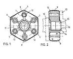
- Figures 1 and 2 show an elastic shaft coupling, which consists of the following parts: a polygonal rubber ring 1, a three-armed hub meter 2 and between the arms 3 to 5 arranged, consisting of two parts sleeve-shaped connecting elements 6 to 8 and a tensioning strap 9.
- a polygonal rubber ring 1 a polygonal rubber ring 1
- a three-armed hub meter 2 between the arms 3 to 5 arranged, consisting of two parts sleeve-shaped connecting elements 6 to 8 and a tensioning strap 9.
- a propeller shaft 10 shown in dashed lines
- the sleeves 6 to 8 not lying on a pitch circle diameter 11 in the relaxed state of the coupling are first connected to the shaft end 10. In this state, both parts are balanced after the tensioning strap 9 has been removed.
Landscapes
- Engineering & Computer Science (AREA)
- General Engineering & Computer Science (AREA)
- Mechanical Engineering (AREA)
- Motor Power Transmission Devices (AREA)
- Shafts, Cranks, Connecting Bars, And Related Bearings (AREA)
Abstract
Description
- Die Erfindung betrifft eine elastische Wellenkupplung zur Verbindung der Endbereiche zweier Maschinenteile, insbesondere zum Verbinden einer Kraftfahrzeug-Getriebewelle mit einer Gelenkwelle, bestehend aus einem üblicherweise polygonalen Gummiring mit einvulkanisiertem, mehrere Arme aufweisendem Nabenstern, zwischen dessen Armen Verbindungs- oder Befestigungselemente angeordnet sind.
- Durch das deutsche Gebrauchsmuster 79 32 960 ist bereits eine elastische Wellenkupplung bekannt, die zur Verbindung zweier Wellenenden dient. Sie besteht aus einem polygonalen Gummiring mit an den Enden zur wechselseitigen Befestigung der Wellenenden anvulkanisierten SpannhUlsen, wobei jede zweite Spannhülse durch den Arm eines Nabensternes gebildet ist. Der Nabenstern besitzt eine zentrale Bohrung zur austauschbaren Aufnahme einer Zentrierhülse, zur Zentrierung des Wellenzapfens eine Antriebswelle.
- Ferner ist durch die DE-AS 26 15 923 eine elastische Wellenkupplung bekannt. Die zwischen den Armen eines Nabensternes liegenden Metallteile sind Arme seines einzelnen Sektorteiles. Die einzelnen Sektorteile sind mittels einer Vorrichtung unter Vorspannung der Gummisäulen aneinander fügbar und durch Schweißen, Kleben oder dergleichen, einen kompletten Wellenstern bildend, miteinander fest verbindbar.
- üblicherweise werden die vorab angesprochenen Wellenkupplungen nabensternseitig mit einem Schiebestück mit Keilwellenprofil versehen. Durch diese Maßnahme ist zwar eine Steckverbindung zwischen der Kupplung und dem einen Wellenende möglich, der axiale Bauraum wird dadurch jedoch erhöht. Ferner ist es nicht möglich, die Kupplung und das eine Wellenende gleichzeitig auszuwuchten.
- Der Erfindung liegt daher die Aufgabe zugrunde, neben der Reduzierung des Bauraumes und des Gewichtes eine Möglichkeit zu schaffen, eine gattungsgemäße Wellenkupplung mit einem Wellenende zusammen auswuchten zu können.
- Diese Aufgabe wird erfindungsgemäß dadurch gelöst, daß die in Umfangsrichtung nicht zentrierten Verbindungs-oder Befestigungselemente mit dem Ende eines mit der Wellenkupplung zusammen auszuwuchtenden Maschinenteiles und der Nabenstern beziehungsweise seine Arme mit dem Ende des anderen Maschinenteiles verbindbar sind. Die Wellenkupplung, die üblicherweise mit einem Spannband versehen ist, wird zunächst einmal mit ihren im entspannten Zustand nicht auf einem Teilkreisdurchmesser angeordneten, zwischen den Armen des Nabensternes liegenden Verbindungs- beziehungsweise Befestigungselementen mit dem einen Wellenende verbunden. Die so verbundenen Teile werden ausgewuchtet (was bisher nicht möglich war), so daß keine Veränderung des Wuchtzustandes bei der Montage an das andere Wellenende eintritt. Bisher wurden beide Teile für sich ausgewuchtet und anschließend miteinander verbunden. Bedingt durch Herstellungstoleranzen, kam es des öfteren vor, daß die Lebensdauer der elastischen Wellenkupplung erheblich reduziert wurde. Sind beide Teile zusammen ausgewuchtet, kann der fixierte Nabenstern beziehungsweise dessen Arme mit dem anderen Wellenende verbunden werden, ohne daß derartige Probleme auftreten.
- Damit derartige Probleme nicht im Laufe der Betriebszeit auftreten können, wird darüberhinaus vorgeschlagen, daß im Bereich des Nabensternes eine Zentrierung vorgesehen ist, die mit dem nicht zu wuchtenden zweiten Maschinenteil zusammenwirkt. Die Zentrierung kann durch mindestens einen vorzugsweise umlaufend ausgebildeten, axialen Ansatz im Bereich der Nabensternbohrung vorgesehen sein, der in eine korrespondierende Ausnehmung am zweiten Maschinenteil eingreift.
- Vorzugsweise sind die Metallteile und/oder der Nabenstern aus Leichtmetall, wie zum Beispiel Aluminium oder einer Legierung daraus, hergestellt, um das Gesamtgewicht der Wellenkupplung weiterhin zu reduzieren.
- Die Erfindung ist in der Zeichnung dargestellt und wird im folgenden näher beschrieben. Es zeigen:
- Figuren 1 und 2 Elastische Wellenkupplung mit Nabenstern und zwischen den Armen des Nabensternes angeordneten hülsenförmigen Verbindungselementen
- Die Figuren 1 und 2 zeigen eine elastische Wellenkupplung, die aus folgenden Teilen besteht: einem polygonalen Gummiring 1, einem dreiarmigen Nabenetern 2 sowie zwischen den Armen 3 bis 5 angeordneten, aus zwei Teilen bestehenden hülsenförmigen Verbindungselementen 6 bis 8 sowie einem Spannband 9. Um die Kuplung mit zum Beispiel einer Gelenkwelle 10 (gestrichelt dargestellt) zusammen auswuchten zu können, werden die im entspannten Zustand der Kupplung nicht auf einem Teilkreisdurchmesser 11 liegenden Hülsen 6 bis 8 zunächst einmal mit dem Wellenende 10 verbunden. In diesem Zustand werden beide Teile ausgewuchtet, nachdem das Spannband 9 entfernt worden ist. Die auf einem beziehungsweise in diesem-Zustand gleichen Teilkreisdurchmesser 11 liegenden Durchgangslöcher 12 in den Armen 3 bis 5 des Nabensternes 2 verändern den Wuchtzustand im Anschluß an die Montage mit dem ebenfalls nur gestrichelt dargestellten Getriebewellenende 13 nicht mehr. Zur Zentrierung des nabensternseitigen Endes der Kupplung gegenüber dem Wellenende 13 ist ein umlaufender Axialansatz 14 im Bereich der Nabensternbohrung 15 angeformt, der in eine korrespondierende Nut 16 des Getriebewellenendes 13 eingreift.
Claims (4)
Applications Claiming Priority (2)
| Application Number | Priority Date | Filing Date | Title |
|---|---|---|---|
| DE19843429519 DE3429519A1 (de) | 1984-08-10 | 1984-08-10 | Elastische wellenkupplung |
| DE3429519 | 1984-08-10 |
Publications (2)
| Publication Number | Publication Date |
|---|---|
| EP0174453A1 true EP0174453A1 (de) | 1986-03-19 |
| EP0174453B1 EP0174453B1 (de) | 1989-05-24 |
Family
ID=6242804
Family Applications (1)
| Application Number | Title | Priority Date | Filing Date |
|---|---|---|---|
| EP85108282A Expired EP0174453B1 (de) | 1984-08-10 | 1985-07-04 | Elastische Wellenkupplung |
Country Status (3)
| Country | Link |
|---|---|
| US (1) | US4696657A (de) |
| EP (1) | EP0174453B1 (de) |
| DE (2) | DE3429519A1 (de) |
Citations (3)
| Publication number | Priority date | Publication date | Assignee | Title |
|---|---|---|---|---|
| FR1410904A (fr) * | 1964-10-09 | 1965-09-10 | Gomma Antivibranti Applic | Perfectionnements aux joints d'accouplement flexibles pour transmissions |
| DE1266578B (de) * | 1964-10-13 | 1968-04-18 | Goetzewerke | Elastische Wellenkupplung |
| FR2102496A5 (de) * | 1970-08-05 | 1972-04-07 | Paulstra Sa |
Family Cites Families (12)
| Publication number | Priority date | Publication date | Assignee | Title |
|---|---|---|---|---|
| DE7932960U1 (de) * | 1981-03-19 | Goetze Ag, 5093 Burscheid | Elastische Wellenkupplung | |
| US1261683A (en) * | 1917-03-08 | 1918-04-02 | Walter J Behn | Universal joint. |
| DE854293C (de) * | 1949-07-12 | 1952-11-04 | Adolf Boge Jun | Elastische Kupplung |
| US2982118A (en) * | 1959-07-18 | 1961-05-02 | Gomma Antivibranti Applic | Resilient transmission joints for shafts |
| US3112626A (en) * | 1961-12-02 | 1963-12-03 | Gomma Antivibranti Applic | Flexible joint for torque transmission |
| DE1425372A1 (de) * | 1963-10-15 | 1969-02-06 | Gomma Antivibranti Applic | Elastische Kupplung zur UEbertragung von Drehmomenten |
| DE1273996B (de) * | 1965-09-20 | 1968-07-25 | Goetzewerke | Drehschwingungsdaempfer fuer Kraftfahrzeug-Scheibenkupplungen |
| DE1284713B (de) * | 1966-10-10 | 1968-12-05 | Goetzewerke | Elastische Wellenkupplung |
| GB1159750A (en) * | 1966-11-26 | 1969-07-30 | Daimler Benz Ag | Improvements relating to Shaft Couplings. |
| FR1532896A (fr) * | 1967-07-27 | 1968-07-12 | Goetzewerke | Accouplement élastique pour arbres |
| DE2019608B2 (de) * | 1970-04-23 | 1971-12-23 | Kirschey, Gerhard, Dipl Ing 5600 Wuppertal Vohwinkel | Elastische wellenkupplung |
| DE2234437A1 (de) * | 1972-07-13 | 1974-01-24 | Freudenberg Carl Fa | Elastische kupplung |
-
1984
- 1984-08-10 DE DE19843429519 patent/DE3429519A1/de not_active Withdrawn
-
1985
- 1985-07-04 DE DE8585108282T patent/DE3570494D1/de not_active Expired
- 1985-07-04 EP EP85108282A patent/EP0174453B1/de not_active Expired
- 1985-08-08 US US06/763,970 patent/US4696657A/en not_active Expired - Fee Related
Patent Citations (3)
| Publication number | Priority date | Publication date | Assignee | Title |
|---|---|---|---|---|
| FR1410904A (fr) * | 1964-10-09 | 1965-09-10 | Gomma Antivibranti Applic | Perfectionnements aux joints d'accouplement flexibles pour transmissions |
| DE1266578B (de) * | 1964-10-13 | 1968-04-18 | Goetzewerke | Elastische Wellenkupplung |
| FR2102496A5 (de) * | 1970-08-05 | 1972-04-07 | Paulstra Sa |
Also Published As
| Publication number | Publication date |
|---|---|
| EP0174453B1 (de) | 1989-05-24 |
| DE3429519A1 (de) | 1986-02-20 |
| US4696657A (en) | 1987-09-29 |
| DE3570494D1 (en) | 1989-06-29 |
Similar Documents
| Publication | Publication Date | Title |
|---|---|---|
| DE3702847C2 (de) | ||
| EP1270987A2 (de) | Aggregatelager in Buchsenform | |
| EP1351796B1 (de) | Verfahren zur herstellung einer gebauten welle | |
| EP0816703A2 (de) | Konusschraubverbindung für Lamellenpaket-Wellenkupplungen | |
| DE3034761A1 (de) | Aussenverzahntes stirnrad | |
| DE19754188A1 (de) | Befestigungsvorrichtung für ein aus einer Radinnen- und einer Radaußenschale bestehendes Fahrzeugrad | |
| EP1299658A1 (de) | Buchse, insbesondere lenkerbuchse | |
| DE3435564A1 (de) | Schlauchhalter | |
| DE3014790C2 (de) | Zwischenlageranordnung, insbesondere für einen Gelenkwellenzug | |
| DE2831470C2 (de) | Verfahren zur Herstellung eines elastischen Kugelgelenks | |
| DE2752445C2 (de) | Elastische Gelenkscheibe für Wellenkupplungen | |
| DE2629480A1 (de) | Sprossenanordnung fuer eine leiter sowie verfahren zur herstellung der sprossenanordnung | |
| DE2247674A1 (de) | Scheibenbremse | |
| DE3516216C2 (de) | ||
| DE8611098U1 (de) | Planetengetriebe | |
| DE2814507A1 (de) | Verfahren zur herstellung eines festsitzenden uebergangsrohres fuer verstellgestaenge und danach hergestelltes verstellgestaenge | |
| DE2318629A1 (de) | Zentriervorrichtung fuer wellenkupplungen o.dgl | |
| DE2518483C2 (de) | Lagereinsatz | |
| DE2630506A1 (de) | Elastische wellenkupplung | |
| DE3048340C2 (de) | Winkelbewegliche Gelenkkupplung | |
| EP0174453A1 (de) | Elastische Wellenkupplung | |
| DE3509129C2 (de) | ||
| DE3522487A1 (de) | Kupplung zum kuppeln umlaufender maschinenteile | |
| DE2243764C2 (de) | Verfahren zum Zusammenbau von Propellernaben für Bootsmotoren | |
| DE3610283A1 (de) | Gelenkverbindung |
Legal Events
| Date | Code | Title | Description |
|---|---|---|---|
| PUAI | Public reference made under article 153(3) epc to a published international application that has entered the european phase |
Free format text: ORIGINAL CODE: 0009012 |
|
| AK | Designated contracting states |
Kind code of ref document: A1 Designated state(s): DE FR GB IT |
|
| 17P | Request for examination filed |
Effective date: 19860725 |
|
| 17Q | First examination report despatched |
Effective date: 19871007 |
|
| GRAA | (expected) grant |
Free format text: ORIGINAL CODE: 0009210 |
|
| AK | Designated contracting states |
Kind code of ref document: B1 Designated state(s): DE FR GB IT |
|
| ITF | It: translation for a ep patent filed | ||
| PGFP | Annual fee paid to national office [announced via postgrant information from national office to epo] |
Ref country code: DE Payment date: 19890609 Year of fee payment: 5 |
|
| REF | Corresponds to: |
Ref document number: 3570494 Country of ref document: DE Date of ref document: 19890629 |
|
| PGFP | Annual fee paid to national office [announced via postgrant information from national office to epo] |
Ref country code: GB Payment date: 19890630 Year of fee payment: 5 |
|
| PGFP | Annual fee paid to national office [announced via postgrant information from national office to epo] |
Ref country code: FR Payment date: 19890711 Year of fee payment: 5 |
|
| GBT | Gb: translation of ep patent filed (gb section 77(6)(a)/1977) | ||
| ITTA | It: last paid annual fee | ||
| ET | Fr: translation filed | ||
| PLBE | No opposition filed within time limit |
Free format text: ORIGINAL CODE: 0009261 |
|
| STAA | Information on the status of an ep patent application or granted ep patent |
Free format text: STATUS: NO OPPOSITION FILED WITHIN TIME LIMIT |
|
| 26N | No opposition filed | ||
| PG25 | Lapsed in a contracting state [announced via postgrant information from national office to epo] |
Ref country code: GB Effective date: 19900704 |
|
| GBPC | Gb: european patent ceased through non-payment of renewal fee | ||
| PG25 | Lapsed in a contracting state [announced via postgrant information from national office to epo] |
Ref country code: FR Effective date: 19910329 |
|
| PG25 | Lapsed in a contracting state [announced via postgrant information from national office to epo] |
Ref country code: DE Effective date: 19910403 |
|
| REG | Reference to a national code |
Ref country code: FR Ref legal event code: ST |