EP0173656B2 - Method and apparatus for welding thin metal sheets - Google Patents
Method and apparatus for welding thin metal sheets Download PDFInfo
- Publication number
- EP0173656B2 EP0173656B2 EP85830207A EP85830207A EP0173656B2 EP 0173656 B2 EP0173656 B2 EP 0173656B2 EP 85830207 A EP85830207 A EP 85830207A EP 85830207 A EP85830207 A EP 85830207A EP 0173656 B2 EP0173656 B2 EP 0173656B2
- Authority
- EP
- European Patent Office
- Prior art keywords
- sheets
- electrodes
- metal sheets
- closed line
- weld
- Prior art date
- Legal status (The legal status is an assumption and is not a legal conclusion. Google has not performed a legal analysis and makes no representation as to the accuracy of the status listed.)
- Expired
Links
- 239000002184 metal Substances 0.000 title claims description 33
- 238000000034 method Methods 0.000 title claims description 15
- 238000003466 welding Methods 0.000 title claims description 12
- 238000010438 heat treatment Methods 0.000 claims 1
- 238000002844 melting Methods 0.000 claims 1
- 230000008018 melting Effects 0.000 claims 1
- 230000000694 effects Effects 0.000 description 5
- 239000000463 material Substances 0.000 description 3
- 230000010355 oscillation Effects 0.000 description 2
- 238000009825 accumulation Methods 0.000 description 1
- 238000005452 bending Methods 0.000 description 1
- 230000005540 biological transmission Effects 0.000 description 1
- 230000015572 biosynthetic process Effects 0.000 description 1
- 239000000356 contaminant Substances 0.000 description 1
- 125000004122 cyclic group Chemical group 0.000 description 1
- 230000003628 erosive effect Effects 0.000 description 1
- 239000007787 solid Substances 0.000 description 1
- 230000003068 static effect Effects 0.000 description 1
Images

Classifications
-
- B—PERFORMING OPERATIONS; TRANSPORTING
- B23—MACHINE TOOLS; METAL-WORKING NOT OTHERWISE PROVIDED FOR
- B23K—SOLDERING OR UNSOLDERING; WELDING; CLADDING OR PLATING BY SOLDERING OR WELDING; CUTTING BY APPLYING HEAT LOCALLY, e.g. FLAME CUTTING; WORKING BY LASER BEAM
- B23K26/00—Working by laser beam, e.g. welding, cutting or boring
- B23K26/20—Bonding
- B23K26/21—Bonding by welding
- B23K26/22—Spot welding
-
- B—PERFORMING OPERATIONS; TRANSPORTING
- B23—MACHINE TOOLS; METAL-WORKING NOT OTHERWISE PROVIDED FOR
- B23K—SOLDERING OR UNSOLDERING; WELDING; CLADDING OR PLATING BY SOLDERING OR WELDING; CUTTING BY APPLYING HEAT LOCALLY, e.g. FLAME CUTTING; WORKING BY LASER BEAM
- B23K11/00—Resistance welding; Severing by resistance heating
- B23K11/30—Features relating to electrodes
- B23K11/3081—Electrodes with a seam contacting part shaped so as to correspond to the shape of the bond area, e.g. for making an annular bond without relative movement in the longitudinal direction of the seam between the electrode holder and the work
Definitions
- the present invention relates to a method of welding superimposed metal sheets.
- the invention relates to a method according to the preamble of appended claim 1.
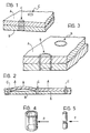
- spot welds For the firm connection of metal sheets (for example to form box or shell structures) it is known to effect welding with "full" spot welds that is of the type illustrated by way of example in Figures 1 and 2 of the appended drawings.
- the spot welds C may be achieved, for example, by electrical resistance welding using a pair of electrodes (not shown) between which the metal sheets are gripped.
- Each spot weld C is substantially cylindrical and forms a monolithic body.
- the spot weld of known type described above presents a zone of stress concentration when the welded structure of which it forms part is subject to stress: in general, the state of tension at the spot weld can reach values up to two to three times the magnitude of the maximum stress foreseeable under static conditions.
- the metallic and metallurgical characteristics of the material of the spot weld are usually poorer than the characteristics of the surrounding zones of the structure. Furthermore typical phenomena of erosion of an electrolytic nature due to the accumulation of scales condensed residues and contaminants of various types facilitate micro-erosion and/or micro-cracks and their propagation, since the spot weld is usually more sensitive to the electrochemical phenomena indicated above.
- the spot welds are thus more readily inclined to break and hence are intrinsically not reliable in certain critical applications from the safety point of view or where very severe stresses arise under the conditions of use. This generally results in the need to make use of an excessive number of weld spots to ensure safety conditions.
- the "full" spot weld of conventional type is considered as a beam element having an infinite rigidity perpendicular to the metal sheets and tightly fixed thereto. If we consider two metal sheets joined by a series of successive spot welds disposed for example along a line, and if these metal sheets are stressed so that a spot weld at the end of the series of welds is loaded with a considerable shear force, this weld is prone to fracture ("fragile fracture”) and the successive spot welds are likely to break in a chain. Indeed, after the breakage of a first spot weld the shear force is transmitted to the successive spot "rigidly" or totally, that is, without being at least partly absorbed in deformation work. The other spot welds may then yield, that is break in succession, so that the fracture propagates like a chain (domino effect).
- a spot weld having a substantially annular, preferably circular, configuration in cross section.
- the welds are able to absorb part of the applied stress in an elastic-plastic manner and thus are not subject to fragile fracture, and furthermore do not display the phenomenon of rigid or total transmission of the stress from one spot weld to the other and chain yielding.
- the present invention proposes an improved method of the previously specified kind, which comprises additionally the features defined in the characterizing portion of the attached claim 1.
- FIG. 3 shows two tubular spot welds S.
- the metal sheets A and B shown in this drawing have been heated locally and fused along a clodes line which is substantially circular so that each weld spot S is constituted essentially by a tubular cylindrical element with an average radius of, for example, 2 mm.
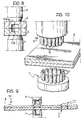
- the tubular spot welds shown in Figure 3 are formed by means of an electrical resistance welding process, as shown in Figure 6.
- two opposing electrodes 6 and 7 are shown, between which the metal sheets A and B to be welded are gripped.
- the electrodes 6 and 7 are connected to a power voltage supply 8 of conventional type. When this supply is energised a current is established between the electrodes 6 and 7 and passes through the metal sheets A and B. The region of the metal sheets A and B through which the current passes is heated strongly by the Joule effect and the material constituting this region is fused.
- the facing ends of the electrodes 6 and 7 have respective axial cavities 6a, 7b such that these ends have an essentially annular cross section.
- the current flowing through the metal sheets A and B is essentially in a tubular region: in this region the material and the metal sheets are fused and subsequently cooled, forming a monolithic structure constituting the tubular spot weld itself.
- bosses 70 may be pre-formed in (at least) one of the metal sheets during the pressing of the metal sheets in the zones of welding. This solution is illustrated in Figure 9.
- FIG 10 illustrates another alternative solution for achieving spot welds by means of electrical resistance welding.
- each electrode 6, 7 is constituted by an array of small needle or wire electrodes 17, 17 disposed along a closed line.
- the electrodes 16. 17 may be supplied with pulses sequentially or simultaneously by means of an electronic control circuit.
- Each electrode 16, 17 forms a small weld point: the spacing between the electrodes must be such as to allow the small weld points to be joined so as to form together the desired spot weld.
Landscapes
- Engineering & Computer Science (AREA)
- Physics & Mathematics (AREA)
- Optics & Photonics (AREA)
- Mechanical Engineering (AREA)
- Plasma & Fusion (AREA)
- Laser Beam Processing (AREA)
- Resistance Welding (AREA)
Applications Claiming Priority (2)
| Application Number | Priority Date | Filing Date | Title |
|---|---|---|---|
| IT6783384 | 1984-08-20 | ||
| IT67833/84A IT1179062B (it) | 1984-08-20 | 1984-08-20 | Procedimento ed apparecchiature per la saldatura di lamiere sottili |
Publications (3)
| Publication Number | Publication Date |
|---|---|
| EP0173656A1 EP0173656A1 (en) | 1986-03-05 |
| EP0173656B1 EP0173656B1 (en) | 1989-08-30 |
| EP0173656B2 true EP0173656B2 (en) | 1992-04-01 |
Family
ID=11305640
Family Applications (1)
| Application Number | Title | Priority Date | Filing Date |
|---|---|---|---|
| EP85830207A Expired EP0173656B2 (en) | 1984-08-20 | 1985-07-29 | Method and apparatus for welding thin metal sheets |
Country Status (6)
| Country | Link |
|---|---|
| US (1) | US4755652A (it) |
| EP (1) | EP0173656B2 (it) |
| JP (1) | JPH0677841B2 (it) |
| DE (1) | DE3572614D1 (it) |
| ES (1) | ES8608367A1 (it) |
| IT (1) | IT1179062B (it) |
Families Citing this family (22)
| Publication number | Priority date | Publication date | Assignee | Title |
|---|---|---|---|---|
| FR2658928A1 (fr) * | 1990-02-26 | 1991-08-30 | Kodak Pathe | Procede de marquage d'un support d'impression et dispositif de mise en óoeuvre du procede. |
| US5201458A (en) * | 1990-10-31 | 1993-04-13 | Seagate Technology, Inc. | Method of welding a head suspension assembly |
| US5437936A (en) * | 1991-05-13 | 1995-08-01 | Johnson; Jeffrey D. | Honeycomb core structure and method and apparatus relating thereto |
| US5187345A (en) * | 1991-11-22 | 1993-02-16 | The Torrington Company | Method of welding retainer rings |
| JPH07115199B2 (ja) * | 1992-03-27 | 1995-12-13 | 新明和工業株式会社 | 弾性体を用いた薄板の抵抗溶接方法及び該方法に使用されるワーク支持具 |
| IT1267357B1 (it) * | 1994-12-23 | 1997-01-28 | Fiat Auto Spa | Metodo di unione per saldatura tra elementi diversi. |
| DE19959090A1 (de) | 1999-12-08 | 2001-06-13 | Prym William Gmbh & Co Kg | Verbindung zwischen zwei- oder mehrflächig aufeinanderliegenden dünnen bahnförmigen Lagen, insbesondere zwischen zwei eine kontinuierliche Behandlung erfahrenden Bänder |
| US7065858B1 (en) | 2000-11-14 | 2006-06-27 | Hutchinson Technology Incorporated | Method for welding components of a disk drive head suspension |
| US6900966B1 (en) | 2001-08-08 | 2005-05-31 | Hutchinson Technology Incorporated | Head suspension with weld pockets and method |
| JP4877906B2 (ja) * | 2005-08-05 | 2012-02-15 | 麒麟麦酒株式会社 | 飲料用又は食品用の密封容器の製造方法 |
| JP5057557B2 (ja) * | 2006-08-29 | 2012-10-24 | ダイハツ工業株式会社 | シリーズスポット溶接方法及び溶接装置 |
| JP2011031267A (ja) * | 2009-07-31 | 2011-02-17 | Daihatsu Motor Co Ltd | 抵抗溶接装置、抵抗溶接方法、及びこれらに用いる電極 |
| JP5491093B2 (ja) * | 2009-07-31 | 2014-05-14 | ダイハツ工業株式会社 | 抵抗溶接装置 |
| CN102834219B (zh) * | 2010-04-28 | 2016-03-16 | 宝马股份公司 | 用于连接两个车辆构件或两个非车辆构件的方法 |
| JOP20200150A1 (ar) * | 2011-04-06 | 2017-06-16 | Esco Group Llc | قطع غيار بأوجه مقواه باستخدام عملية التقسية المصلدة والطريقة والتجميع المرافق للتصنيع |
| JP5880032B2 (ja) * | 2011-12-27 | 2016-03-08 | トヨタ自動車株式会社 | レーザー溶接方法 |
| EP2857137A4 (en) * | 2012-05-25 | 2016-01-20 | Korea Ind Tech Inst | ELECTRODE FOR RESISTANCE SPOT WELDING AND METHOD FOR RESISTANCE SPOT WELDING THEREWITH |
| JP6046955B2 (ja) * | 2012-08-28 | 2016-12-21 | マニー株式会社 | 硝子体手術用プローブ及びその製造方法 |
| DE102013014701A1 (de) | 2013-09-05 | 2015-03-05 | GM Global Technology Operations LLC (n. d. Ges. d. Staates Delaware) | Schweißanordnung zum Verschweißen eines Verbindungsabschnitts und Verfahren zum Verschweißen des Verbindungsabschnitts mit der Schweißanordnung |
| US20150314363A1 (en) * | 2014-04-30 | 2015-11-05 | GM Global Technology Operations LLC | Method of forming a vehicle body structure from a pre-welded blank assembly |
| US20160053899A1 (en) * | 2014-08-20 | 2016-02-25 | Swagelok Company | Valve with welded diaphragm to assist opening force |
| CN111014923A (zh) * | 2020-02-18 | 2020-04-17 | 吉林大学 | 不等厚板的电阻点焊装置及方法 |
Family Cites Families (15)
| Publication number | Priority date | Publication date | Assignee | Title |
|---|---|---|---|---|
| US1281454A (en) * | 1917-03-15 | 1918-10-15 | Gen Fire Proofing Company | Electric welding. |
| US2379187A (en) * | 1943-12-11 | 1945-06-26 | Westinghouse Electric Corp | Welding and brazing electrode |
| US2474129A (en) * | 1947-08-14 | 1949-06-21 | Stewart Warner Corp | Welding apparatus |
| US3089947A (en) * | 1960-12-20 | 1963-05-14 | Frungel Frank | Arrangement and method for electrical impulse welding |
| CH451355A (de) * | 1965-03-30 | 1968-05-15 | Steigerwald Gmbh K H | Verfahren zur Materialbearbeitung mit Strahlungsenergie |
| FR1524116A (fr) * | 1967-01-26 | 1968-05-10 | Soudure Elec Languepin | Procédé d'assemblage par soudage de tôles empilées, outillage de mise en oeuvre de ce procédé et blocs de tôles ainsi assemblées |
| US3619550A (en) * | 1969-09-25 | 1971-11-09 | Laser Systems Corp | Laser beam machine tool with beam manipulating apparatus |
| US3969604A (en) * | 1973-10-04 | 1976-07-13 | Ford Motor Company | Method of welding galvanized steel |
| US4237363A (en) * | 1977-02-04 | 1980-12-02 | Lemelson Jerome H | Beam welding apparatus and method |
| US4354090A (en) * | 1979-10-23 | 1982-10-12 | Sws Incorporated | Z-bar guide apparatus and method of butt welding |
| JPS5868492A (ja) * | 1981-10-19 | 1983-04-23 | Toshiba Corp | レ−ザ−スポツト溶接機 |
| JPS5868491A (ja) * | 1981-10-19 | 1983-04-23 | Toshiba Corp | レ−ザ−スポツト溶接機 |
| JPS5939491A (ja) * | 1982-08-30 | 1984-03-03 | Matsushita Electric Works Ltd | 金属薄板のレ−ザ溶接方法 |
| JPS5992189A (ja) * | 1982-11-18 | 1984-05-28 | Toshiba Corp | 鋼板枠の製造方法 |
| FR2547756B1 (fr) * | 1983-06-24 | 1986-06-06 | Sciaky Sa | Procede et installation de soudage par point a faisceau laser |
-
1984
- 1984-08-20 IT IT67833/84A patent/IT1179062B/it active
-
1985
- 1985-07-29 DE DE8585830207T patent/DE3572614D1/de not_active Expired
- 1985-07-29 EP EP85830207A patent/EP0173656B2/en not_active Expired
- 1985-08-19 ES ES546261A patent/ES8608367A1/es not_active Expired
- 1985-08-20 JP JP60183787A patent/JPH0677841B2/ja not_active Expired - Lifetime
- 1985-08-20 US US06/767,541 patent/US4755652A/en not_active Expired - Fee Related
Also Published As
| Publication number | Publication date |
|---|---|
| ES546261A0 (es) | 1986-07-16 |
| ES8608367A1 (es) | 1986-07-16 |
| US4755652A (en) | 1988-07-05 |
| DE3572614D1 (en) | 1989-10-05 |
| EP0173656A1 (en) | 1986-03-05 |
| IT8467833A0 (it) | 1984-08-20 |
| JPH0677841B2 (ja) | 1994-10-05 |
| JPS6163392A (ja) | 1986-04-01 |
| IT1179062B (it) | 1987-09-16 |
| EP0173656B1 (en) | 1989-08-30 |
| IT8467833A1 (it) | 1986-02-20 |
Similar Documents
| Publication | Publication Date | Title |
|---|---|---|
| EP0173656B2 (en) | Method and apparatus for welding thin metal sheets | |
| JP3636603B2 (ja) | 接続板及び接続板の接続方法 | |
| EP0173655A1 (en) | Sheet metal welding process | |
| KR100218198B1 (ko) | 단자와 배선접속방법 및 그 접속장치 | |
| US4476372A (en) | Spot welding electrode | |
| US3524042A (en) | Method of making mechanical and welded joint | |
| CA2979104A1 (en) | Dissimilar material joined body and dissimilar material joining method | |
| JP3921611B2 (ja) | 複数重ね鋼板への軸状部品溶接方法 | |
| US6594886B2 (en) | Method of fuse manufacture and a battery pack containing that fuse | |
| US20120181890A1 (en) | Method and system for joining stator wires | |
| JP5441551B2 (ja) | 抵抗溶接方法 | |
| JPH09330697A (ja) | 電 池 | |
| KR100245481B1 (ko) | 직류 아크로의 로바닥의 구조 | |
| NL1007845C2 (nl) | Laselement voor thermoplastische delen. | |
| US4843205A (en) | Resistance weld joining of high electrical conductivity copper foil | |
| JP4224050B2 (ja) | ヒーターチップの熱電対取付構造および熱電対取付方法 | |
| CA2073761C (en) | Multi-point welding method and catalyst support produced thereby | |
| JPH0691377A (ja) | 被溶接部材およびその溶接方法 | |
| JP6533654B2 (ja) | 電気溶接装置 | |
| SU1539022A1 (ru) | Устройство дл креплени электрода | |
| US4193107A (en) | Variable capacitor | |
| JPS63317265A (ja) | サンドイッチ制振鋼板における部品溶接方法 | |
| KR900000535B1 (ko) | 전동기용 프레임의 제조방법 | |
| EP0127869B1 (en) | Integral support unit for a vehicle rear wheel | |
| RU2035822C1 (ru) | Магнитопровод и способ его изготовления |
Legal Events
| Date | Code | Title | Description |
|---|---|---|---|
| PUAI | Public reference made under article 153(3) epc to a published international application that has entered the european phase |
Free format text: ORIGINAL CODE: 0009012 |
|
| AK | Designated contracting states |
Kind code of ref document: A1 Designated state(s): DE FR GB SE |
|
| 17P | Request for examination filed |
Effective date: 19860213 |
|
| 17Q | First examination report despatched |
Effective date: 19861212 |
|
| GRAA | (expected) grant |
Free format text: ORIGINAL CODE: 0009210 |
|
| AK | Designated contracting states |
Kind code of ref document: B1 Designated state(s): DE FR GB SE |
|
| REF | Corresponds to: |
Ref document number: 3572614 Country of ref document: DE Date of ref document: 19891005 |
|
| ET | Fr: translation filed | ||
| PLBI | Opposition filed |
Free format text: ORIGINAL CODE: 0009260 |
|
| 26 | Opposition filed |
Opponent name: BAYERISCHE MOTOREN WERKE AG, PATENTABTEILUNG AJ-3, Effective date: 19900522 |
|
| PUAH | Patent maintained in amended form |
Free format text: ORIGINAL CODE: 0009272 |
|
| STAA | Information on the status of an ep patent application or granted ep patent |
Free format text: STATUS: PATENT MAINTAINED AS AMENDED |
|
| 27A | Patent maintained in amended form |
Effective date: 19920401 |
|
| AK | Designated contracting states |
Kind code of ref document: B2 Designated state(s): DE FR GB SE |
|
| ET3 | Fr: translation filed ** decision concerning opposition | ||
| PGFP | Annual fee paid to national office [announced via postgrant information from national office to epo] |
Ref country code: GB Payment date: 19930615 Year of fee payment: 9 |
|
| PGFP | Annual fee paid to national office [announced via postgrant information from national office to epo] |
Ref country code: DE Payment date: 19930621 Year of fee payment: 9 |
|
| PGFP | Annual fee paid to national office [announced via postgrant information from national office to epo] |
Ref country code: SE Payment date: 19930623 Year of fee payment: 9 |
|
| PGFP | Annual fee paid to national office [announced via postgrant information from national office to epo] |
Ref country code: FR Payment date: 19930730 Year of fee payment: 9 |
|
| PG25 | Lapsed in a contracting state [announced via postgrant information from national office to epo] |
Ref country code: GB Effective date: 19940729 |
|
| PG25 | Lapsed in a contracting state [announced via postgrant information from national office to epo] |
Ref country code: SE Effective date: 19940730 |
|
| EUG | Se: european patent has lapsed |
Ref document number: 85830207.8 Effective date: 19950210 |
|
| GBPC | Gb: european patent ceased through non-payment of renewal fee |
Effective date: 19940729 |
|
| PG25 | Lapsed in a contracting state [announced via postgrant information from national office to epo] |
Ref country code: FR Effective date: 19950331 |
|
| PG25 | Lapsed in a contracting state [announced via postgrant information from national office to epo] |
Ref country code: DE Effective date: 19950401 |
|
| EUG | Se: european patent has lapsed |
Ref document number: 85830207.8 |
|
| REG | Reference to a national code |
Ref country code: FR Ref legal event code: ST |