EP0173656B1 - Method and apparatus for welding thin metal sheets - Google Patents
Method and apparatus for welding thin metal sheets Download PDFInfo
- Publication number
- EP0173656B1 EP0173656B1 EP85830207A EP85830207A EP0173656B1 EP 0173656 B1 EP0173656 B1 EP 0173656B1 EP 85830207 A EP85830207 A EP 85830207A EP 85830207 A EP85830207 A EP 85830207A EP 0173656 B1 EP0173656 B1 EP 0173656B1
- Authority
- EP
- European Patent Office
- Prior art keywords
- sheets
- electrodes
- metal sheets
- weld
- cavity
- Prior art date
- Legal status (The legal status is an assumption and is not a legal conclusion. Google has not performed a legal analysis and makes no representation as to the accuracy of the status listed.)
- Expired
Links
Images


Classifications
-
- B—PERFORMING OPERATIONS; TRANSPORTING
- B23—MACHINE TOOLS; METAL-WORKING NOT OTHERWISE PROVIDED FOR
- B23K—SOLDERING OR UNSOLDERING; WELDING; CLADDING OR PLATING BY SOLDERING OR WELDING; CUTTING BY APPLYING HEAT LOCALLY, e.g. FLAME CUTTING; WORKING BY LASER BEAM
- B23K26/00—Working by laser beam, e.g. welding, cutting or boring
- B23K26/20—Bonding
- B23K26/21—Bonding by welding
- B23K26/22—Spot welding
-
- B—PERFORMING OPERATIONS; TRANSPORTING
- B23—MACHINE TOOLS; METAL-WORKING NOT OTHERWISE PROVIDED FOR
- B23K—SOLDERING OR UNSOLDERING; WELDING; CLADDING OR PLATING BY SOLDERING OR WELDING; CUTTING BY APPLYING HEAT LOCALLY, e.g. FLAME CUTTING; WORKING BY LASER BEAM
- B23K11/00—Resistance welding; Severing by resistance heating
- B23K11/30—Features relating to electrodes
- B23K11/3081—Electrodes with a seam contacting part shaped so as to correspond to the shape of the bond area, e.g. for making an annular bond without relative movement in the longitudinal direction of the seam between the electrode holder and the work
Definitions
- the present invention relates to a method of welding superimposed metal sheets.
- the invention relates to a method according to the preamble of appended claim 1.
- spot welds For the firm connection of metal sheets (for example to form box or shell structures) it is known to effect welding with "full" spot welds that is of the type illustrated by way of example in Figures 1 and 2 of the appended drawings.
- the spot welds C may be achieved, for example, by electrical resistance welding using a pair of electrodes (not shown) between which the metal sheets are gripped.
- Each spot weld C is substantially cylindrical and forms a monolithic body.
- the spot weld of known type described above presents a zone of stress concentration when the welded structure of which it forms part is subject to stress: in general, the state of tension at the spot weld can reach values up to two to three times the magnitude of the maximum stress foreseeable under static conditions.
- the metallic and metallurgical characteristics of the material of the spot weld are usually poorer than the characteristics of the surrounding zones of the structure. Furthermore typical phenomena of erosion of an electrolytic nature due to the accumulation of scales condensed residues and contaminants of various types facilitate micro- erosion and/or micro-cracks and their propagation, since the spot weld is usually more sensitive to the electrochemical phenomena indicated above.
- the spot welds are thus more readily inclined to break and hence are intrinsically not reliable in certain critical applications from the safety point of view or where very severe stresses arise under the conditions of use. This generally results in the need to make use of an excessive number of weld spots to ensure safety conditions.
- the "full" spot weld of conventional type is considered as a beam element having an infinite rigidity perpendicular to the metal sheets and tightly fixed thereto. If we consider two metal sheets joined by a series of successive spot welds disposed for example along a line, and if these metal sheets are stressed so that a spot weld at the end of the series of welds is loaded with a considerable shear force, this weld is prone to fracture ("fragile fracture”) and the successive spot welds are likely to break in a chain. Indeed, after the breakage of a first spot weld the shear force is transmitted to the successive spot "rigidly" or totally, that is, without being at least partly absorbed in deformation work. The other spot welds may then yield, that is break in succession, so that the fracture propagates like a chain (domino effect).
- a spot weld having a substantially annular, preferably circular, configuration in cross section.
- the welds are able to absorb part of the applied stress in an elastic-plastic manner and thus are not subject to fragile fracture, and furthermore do not display the phenomenon of "rigid” or total transmission of the stress from one spot weld to the other and chain yielding.
- US-A-2 474 129 discloses a method according to the preamble of the annexed claim 1 for the obtention of annular seam welds around apertures preexisting in the metal sheets to be welded.
- one electrode is kept fixed in contact with one metal sheet while the other electrode touches the other metal sheet in one point only.
- the said other electrode is circularly rocked about a skew axis so as to make its contact point move about a circle on the metal sheet.
- a continuous series of spot welds a circular seam weld is obtained.
- the present invention proposes an improved method of the previously specified kind, which comprises additionally the features defined in the characterizing portion of the attached claim 1.
- Figures 4 and 5 show how a thin- walled tubular structural element (Figure 4) is much more difficult to break by a concentrated impact, for example with a chisel, than a solid cylindrical structure having the same resistant section strength (Figure 5).
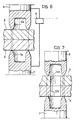
- the tubular spot welds shown in Figure 3 are formed by means of an electrical resistance welding process, as shown in Figure 6.
- two opposing electrodes 6 and 7 are shown, between which the metal sheets A and B to be welded are gripped.
- the electrodes 6 and 7 are connected to a power voltage supply 8 of conventional type. When this supply is energised a current is established between the electrodes 6 and 7 and passes through the metal sheets A and B. The region of the metal sheets A and B through which the current passes is heated strongly by the Joule effect and the material constituting this region is fused.
- the facing ends of the electrodes 6 and 7 have respective axial cavities 6a, 7b such that these ends have an essentially annular cross section.
- the current flowing through the metal sheets A and B is essentially in a tubular region: in this region the material and the metal sheets are fused and subsequently cooled, forming a monolithic structure constituting the tubular spot weld itself.
- bosses 70 may be pre-formed in (at least) one of the metal sheets during the pressing of the metal sheets in the zones of welding. This solution is illustrated in Figure 9.
- FIG 10 illustrates another alternative solution for achieving spot welds by means of electrical resistance welding.
- each electrode 6, 7 is constituted by an array of small needle or wire electrodes 17, 17 disposed along a closed line.
- the electrodes 16, 17 may be supplied with pulses sequentially or simultaneously by means of an electronic control circuit.
- Each electrode 16, 17 forms a small weld point: the spacing between the electrodes must be such as to allow the small weld points to be joined so as to form together the desired spot weld.
Description
- The present invention relates to a method of welding superimposed metal sheets. In particular, the invention relates to a method according to the preamble of appended claim 1.
- For the firm connection of metal sheets (for example to form box or shell structures) it is known to effect welding with "full" spot welds that is of the type illustrated by way of example in Figures 1 and 2 of the appended drawings. In these Figures two juxtaposed metal sheets A and B are joined by spot welds C. The spot welds C may be achieved, for example, by electrical resistance welding using a pair of electrodes (not shown) between which the metal sheets are gripped. Each spot weld C is substantially cylindrical and forms a monolithic body.
- The spot weld of known type described above presents a zone of stress concentration when the welded structure of which it forms part is subject to stress: in general, the state of tension at the spot weld can reach values up to two to three times the magnitude of the maximum stress foreseeable under static conditions.
- When a structure having "full" spot welds of conventional type is subject to vibrational loads (and, in general, to cyclic dynamic loads) the problem arises of possible failure of the spot welds or of their rupture by fatigue.
- Indeed, when the location of use involves repeated impacts, vibrations, etc., these stresses generate oscillations which give rise to resonances and relative modal forms of oscillation of the structure formed by the metal sheets. The bending corresponding to several modal forms may have an amplitude of the order of the thickness of the metal sheet as is seen in Figure 2. Clearly under these conditions strong concentrations of oscillating tensions which are variable in sign are created and cause fatigue of the spot welds.
- The metallic and metallurgical characteristics of the material of the spot weld are usually poorer than the characteristics of the surrounding zones of the structure. Furthermore typical phenomena of erosion of an electrolytic nature due to the accumulation of scales condensed residues and contaminants of various types facilitate micro- erosion and/or micro-cracks and their propagation, since the spot weld is usually more sensitive to the electrochemical phenomena indicated above. The spot welds are thus more readily inclined to break and hence are intrinsically not reliable in certain critical applications from the safety point of view or where very severe stresses arise under the conditions of use. This generally results in the need to make use of an excessive number of weld spots to ensure safety conditions.
- In structural calculations, the "full" spot weld of conventional type is considered as a beam element having an infinite rigidity perpendicular to the metal sheets and tightly fixed thereto. If we consider two metal sheets joined by a series of successive spot welds disposed for example along a line, and if these metal sheets are stressed so that a spot weld at the end of the series of welds is loaded with a considerable shear force, this weld is prone to fracture ("fragile fracture") and the successive spot welds are likely to break in a chain. Indeed, after the breakage of a first spot weld the shear force is transmitted to the successive spot "rigidly" or totally, that is, without being at least partly absorbed in deformation work. The other spot welds may then yield, that is break in succession, so that the fracture propagates like a chain (domino effect).
- The disadvantages of the full spot weld may be overcome by a spot weld having a substantially annular, preferably circular, configuration in cross section.
- The weld thus effected, together with the metal sheets attached thereby constitute a type of "box" which is able to absorb part of the stress applied to the structure of which it forms part in an elastic-plastic manner. Thus for example, in the case of two metal sheets joined by a series of tubular spot welds disposed in succession along a line, the welds are able to absorb part of the applied stress in an elastic-plastic manner and thus are not subject to fragile fracture, and furthermore do not display the phenomenon of "rigid" or total transmission of the stress from one spot weld to the other and chain yielding.
- US-A-2 474 129 discloses a method according to the preamble of the annexed claim 1 for the obtention of annular seam welds around apertures preexisting in the metal sheets to be welded. According to this known method one electrode is kept fixed in contact with one metal sheet while the other electrode touches the other metal sheet in one point only. By means of a control mechanism including an eccentric the said other electrode is circularly rocked about a skew axis so as to make its contact point move about a circle on the metal sheet. Thus by means of a continuous series of spot welds a circular seam weld is obtained.
- Another method of resistance welding a stack of thin metal sheets with the formation of a tubular welded zone is disclosed in FR-A-1 524 116.
- The present invention proposes an improved method of the previously specified kind, which comprises additionally the features defined in the characterizing portion of the attached claim 1.
- Further characteristics and advantages of the invention will become apparent from the detailed description which follows, given with reference to the appended drawings, provided purely by way of non-limiting example in which:
- Figures 1 and 2, already described, show two sheet metal portions joined by "full" spot welds according to the prior art,
- Figure 3 shows two sheet metal portions joined by "tubular" spot welds on an enlarged scale,
- Figures 4 and 5 show the different shear behaviour of a tubular element and of a full element with the same section,
- Figure 6 shows schematically apparatus which can be used to effect spot welding of the type shown in Figure 2,
- Figures 7 to 10 show variants of execution of the welding method according to the invention.
- Figure 3 shows two tubular spot welds S. The metal sheets A and B shown in this drawing have been heated locally and fused along a closed line which is substantially circular so that each weld spot S is constituted essentially by a tubular cylindrical element with an average radius of, for example, 2 mm.
- In order to effect the spot weld S of Figure 3 the apparatus shown in Figure 6 may be used.
- The improved capacity of the spot welds of Figure 3 to withstand knocks and impact is illustrated in Figures 4 and 5 which show how a thin- walled tubular structural element (Figure 4) is much more difficult to break by a concentrated impact, for example with a chisel, than a solid cylindrical structure having the same resistant section strength (Figure 5).
- The tubular spot welds shown in Figure 3 are formed by means of an electrical resistance welding process, as shown in Figure 6. In this Figure, two
opposing electrodes electrodes power voltage supply 8 of conventional type. When this supply is energised a current is established between theelectrodes electrodes axial cavities 6a, 7b such that these ends have an essentially annular cross section. As a result of this shape of the ends of the electrodes, the current flowing through the metal sheets A and B is essentially in a tubular region: in this region the material and the metal sheets are fused and subsequently cooled, forming a monolithic structure constituting the tubular spot weld itself. - With the arrangement of the electrodes shown in Figure 6, if problems of shunting arise or if the current paths in the metal sheets A, B tend to move towards the interior of the spot weld, a pulsed current can be supplied to the
electrode - In order to avoid shunting problems, that is, movement of the current paths towards the centre of the spot weld (and hence to avoid the formation of a core in the zone which should otherwise be empty) according to the invention recourse is made to the solutions illustrated in Figures 7 and 8: in each weld zone,
holes - Alternatively
bosses 70 may be pre-formed in (at least) one of the metal sheets during the pressing of the metal sheets in the zones of welding. This solution is illustrated in Figure 9. - Figure 10 illustrates another alternative solution for achieving spot welds by means of electrical resistance welding. According to this solution, each
electrode wire electrodes electrodes electrode
Claims (7)
Applications Claiming Priority (2)
| Application Number | Priority Date | Filing Date | Title |
|---|---|---|---|
| IT6783384 | 1984-08-20 | ||
| IT67833/84A IT1179062B (en) | 1984-08-20 | 1984-08-20 | PROCESS AND EQUIPMENT FOR THE WELDING OF THIN SHEETS |
Publications (3)
| Publication Number | Publication Date |
|---|---|
| EP0173656A1 EP0173656A1 (en) | 1986-03-05 |
| EP0173656B1 true EP0173656B1 (en) | 1989-08-30 |
| EP0173656B2 EP0173656B2 (en) | 1992-04-01 |
Family
ID=11305640
Family Applications (1)
| Application Number | Title | Priority Date | Filing Date |
|---|---|---|---|
| EP85830207A Expired EP0173656B2 (en) | 1984-08-20 | 1985-07-29 | Method and apparatus for welding thin metal sheets |
Country Status (6)
| Country | Link |
|---|---|
| US (1) | US4755652A (en) |
| EP (1) | EP0173656B2 (en) |
| JP (1) | JPH0677841B2 (en) |
| DE (1) | DE3572614D1 (en) |
| ES (1) | ES8608367A1 (en) |
| IT (1) | IT1179062B (en) |
Cited By (1)
| Publication number | Priority date | Publication date | Assignee | Title |
|---|---|---|---|---|
| DE102013014701A1 (en) | 2013-09-05 | 2015-03-05 | GM Global Technology Operations LLC (n. d. Ges. d. Staates Delaware) | Welding assembly for welding a connection portion and method for welding the connection portion to the welding assembly |
Families Citing this family (21)
| Publication number | Priority date | Publication date | Assignee | Title |
|---|---|---|---|---|
| FR2658928A1 (en) * | 1990-02-26 | 1991-08-30 | Kodak Pathe | METHOD FOR MARKING A PRINTING MEDIUM AND DEVICE FOR IMPLEMENTING THE METHOD. |
| US5201458A (en) * | 1990-10-31 | 1993-04-13 | Seagate Technology, Inc. | Method of welding a head suspension assembly |
| US5437936A (en) * | 1991-05-13 | 1995-08-01 | Johnson; Jeffrey D. | Honeycomb core structure and method and apparatus relating thereto |
| US5187345A (en) * | 1991-11-22 | 1993-02-16 | The Torrington Company | Method of welding retainer rings |
| JPH07115199B2 (en) * | 1992-03-27 | 1995-12-13 | 新明和工業株式会社 | Method for resistance welding thin plate using elastic body and work support used in the method |
| IT1267357B1 (en) * | 1994-12-23 | 1997-01-28 | Fiat Auto Spa | METHOD OF UNION FOR WELDING BETWEEN DIFFERENT ELEMENTS. |
| DE19959090A1 (en) | 1999-12-08 | 2001-06-13 | Prym William Gmbh & Co Kg | Connection between two or more surface-lying thin web-shaped layers, in particular between two strips undergoing continuous treatment |
| US7065858B1 (en) | 2000-11-14 | 2006-06-27 | Hutchinson Technology Incorporated | Method for welding components of a disk drive head suspension |
| US6900966B1 (en) | 2001-08-08 | 2005-05-31 | Hutchinson Technology Incorporated | Head suspension with weld pockets and method |
| JP4877906B2 (en) * | 2005-08-05 | 2012-02-15 | 麒麟麦酒株式会社 | Method for producing sealed container for beverage or food |
| JP5057557B2 (en) * | 2006-08-29 | 2012-10-24 | ダイハツ工業株式会社 | Series spot welding method and welding apparatus |
| JP5491093B2 (en) * | 2009-07-31 | 2014-05-14 | ダイハツ工業株式会社 | Resistance welding equipment |
| JP2011031267A (en) * | 2009-07-31 | 2011-02-17 | Daihatsu Motor Co Ltd | Resistance welding apparatus, resistance welding method, and electrode used therefor |
| CN102834626B (en) * | 2010-04-28 | 2015-06-24 | 宝马股份公司 | Component connection and method for connecting components |
| JOP20200150A1 (en) * | 2011-04-06 | 2017-06-16 | Esco Group Llc | Hardfaced wearpart using brazing and associated method and assembly for manufacturing |
| JP5880032B2 (en) * | 2011-12-27 | 2016-03-08 | トヨタ自動車株式会社 | Laser welding method |
| US20150158110A1 (en) * | 2012-05-25 | 2015-06-11 | Korea Institute Of Industrial Technology | Electrode for resistance spot welding and a method for resistance spot welding using the same |
| JP6046955B2 (en) * | 2012-08-28 | 2016-12-21 | マニー株式会社 | Vitreous surgery probe and method of manufacturing the same |
| US20150314363A1 (en) * | 2014-04-30 | 2015-11-05 | GM Global Technology Operations LLC | Method of forming a vehicle body structure from a pre-welded blank assembly |
| US20160053899A1 (en) * | 2014-08-20 | 2016-02-25 | Swagelok Company | Valve with welded diaphragm to assist opening force |
| CN111014923A (en) * | 2020-02-18 | 2020-04-17 | 吉林大学 | Resistance spot welding device and method for unequal-thickness plates |
Family Cites Families (15)
| Publication number | Priority date | Publication date | Assignee | Title |
|---|---|---|---|---|
| US1281454A (en) * | 1917-03-15 | 1918-10-15 | Gen Fire Proofing Company | Electric welding. |
| US2379187A (en) * | 1943-12-11 | 1945-06-26 | Westinghouse Electric Corp | Welding and brazing electrode |
| US2474129A (en) * | 1947-08-14 | 1949-06-21 | Stewart Warner Corp | Welding apparatus |
| US3089947A (en) * | 1960-12-20 | 1963-05-14 | Frungel Frank | Arrangement and method for electrical impulse welding |
| CH451355A (en) * | 1965-03-30 | 1968-05-15 | Steigerwald Gmbh K H | Process for material processing with radiant energy |
| FR1524116A (en) * | 1967-01-26 | 1968-05-10 | Soudure Elec Languepin | Assembly process by welding stacked sheets, tools for implementing this process and blocks of sheets thus assembled |
| US3619550A (en) * | 1969-09-25 | 1971-11-09 | Laser Systems Corp | Laser beam machine tool with beam manipulating apparatus |
| US3969604A (en) * | 1973-10-04 | 1976-07-13 | Ford Motor Company | Method of welding galvanized steel |
| US4237363A (en) * | 1977-02-04 | 1980-12-02 | Lemelson Jerome H | Beam welding apparatus and method |
| US4354090A (en) * | 1979-10-23 | 1982-10-12 | Sws Incorporated | Z-bar guide apparatus and method of butt welding |
| JPS5868491A (en) * | 1981-10-19 | 1983-04-23 | Toshiba Corp | Laser spot welder |
| JPS5868492A (en) * | 1981-10-19 | 1983-04-23 | Toshiba Corp | Laser spot welder |
| JPS5939491A (en) * | 1982-08-30 | 1984-03-03 | Matsushita Electric Works Ltd | Laser welding method of thin metallic sheet |
| JPS5992189A (en) * | 1982-11-18 | 1984-05-28 | Toshiba Corp | Production of steel plate frame |
| FR2547756B1 (en) * | 1983-06-24 | 1986-06-06 | Sciaky Sa | LASER BEAM POINT WELDING PROCESS AND INSTALLATION |
-
1984
- 1984-08-20 IT IT67833/84A patent/IT1179062B/en active
-
1985
- 1985-07-29 EP EP85830207A patent/EP0173656B2/en not_active Expired
- 1985-07-29 DE DE8585830207T patent/DE3572614D1/en not_active Expired
- 1985-08-19 ES ES546261A patent/ES8608367A1/en not_active Expired
- 1985-08-20 US US06/767,541 patent/US4755652A/en not_active Expired - Fee Related
- 1985-08-20 JP JP60183787A patent/JPH0677841B2/en not_active Expired - Lifetime
Cited By (1)
| Publication number | Priority date | Publication date | Assignee | Title |
|---|---|---|---|---|
| DE102013014701A1 (en) | 2013-09-05 | 2015-03-05 | GM Global Technology Operations LLC (n. d. Ges. d. Staates Delaware) | Welding assembly for welding a connection portion and method for welding the connection portion to the welding assembly |
Also Published As
| Publication number | Publication date |
|---|---|
| IT8467833A1 (en) | 1986-02-20 |
| EP0173656A1 (en) | 1986-03-05 |
| JPH0677841B2 (en) | 1994-10-05 |
| ES8608367A1 (en) | 1986-07-16 |
| EP0173656B2 (en) | 1992-04-01 |
| US4755652A (en) | 1988-07-05 |
| DE3572614D1 (en) | 1989-10-05 |
| IT1179062B (en) | 1987-09-16 |
| ES546261A0 (en) | 1986-07-16 |
| JPS6163392A (en) | 1986-04-01 |
| IT8467833A0 (en) | 1984-08-20 |
Similar Documents
| Publication | Publication Date | Title |
|---|---|---|
| EP0173656B1 (en) | Method and apparatus for welding thin metal sheets | |
| US4476372A (en) | Spot welding electrode | |
| KR100218198B1 (en) | Method of connecting wire to terminal and apparatus therefor | |
| US4290074A (en) | Ink drop generator for ink jet printer | |
| JP2008246538A (en) | Resistance welding method | |
| JP3921611B2 (en) | Welding method for shaft-like parts to multiple steel sheets | |
| CA2979104A1 (en) | Dissimilar material joined body and dissimilar material joining method | |
| US3524042A (en) | Method of making mechanical and welded joint | |
| US6594886B2 (en) | Method of fuse manufacture and a battery pack containing that fuse | |
| KR20040017216A (en) | Reinforcement member for a bushing tip plate and method of reinforcing the plate | |
| JP5441551B2 (en) | Resistance welding method | |
| JP2862102B2 (en) | Method for manufacturing impeller for compressor | |
| JP4919570B2 (en) | Bush having terminal ear and method of manufacturing the bush | |
| FI63210C (en) | STROEMMATARE FOER SMAELT MATERIAL | |
| US5041711A (en) | Spot welding electrode | |
| NL1007845C2 (en) | Welding element for thermoplastic parts. | |
| EP0510209B1 (en) | Method of multispot-welding and carrier obtained by said method | |
| US4193107A (en) | Variable capacitor | |
| US4843205A (en) | Resistance weld joining of high electrical conductivity copper foil | |
| KR100548015B1 (en) | Electrode for electric resistance welding | |
| WO2024034173A1 (en) | Resistance welding device and resistance welding method | |
| US4861954A (en) | Process for connecting conductive parts of an electrical switch component | |
| JPH0999374A (en) | Spot welding equipment | |
| SU880662A1 (en) | Electrode for resistance welding | |
| KR900000535B1 (en) | Manufacture of motor frame |
Legal Events
| Date | Code | Title | Description |
|---|---|---|---|
| PUAI | Public reference made under article 153(3) epc to a published international application that has entered the european phase |
Free format text: ORIGINAL CODE: 0009012 |
|
| AK | Designated contracting states |
Kind code of ref document: A1 Designated state(s): DE FR GB SE |
|
| 17P | Request for examination filed |
Effective date: 19860213 |
|
| 17Q | First examination report despatched |
Effective date: 19861212 |
|
| GRAA | (expected) grant |
Free format text: ORIGINAL CODE: 0009210 |
|
| AK | Designated contracting states |
Kind code of ref document: B1 Designated state(s): DE FR GB SE |
|
| REF | Corresponds to: |
Ref document number: 3572614 Country of ref document: DE Date of ref document: 19891005 |
|
| ET | Fr: translation filed | ||
| PLBI | Opposition filed |
Free format text: ORIGINAL CODE: 0009260 |
|
| 26 | Opposition filed |
Opponent name: BAYERISCHE MOTOREN WERKE AG, PATENTABTEILUNG AJ-3, Effective date: 19900522 |
|
| PUAH | Patent maintained in amended form |
Free format text: ORIGINAL CODE: 0009272 |
|
| STAA | Information on the status of an ep patent application or granted ep patent |
Free format text: STATUS: PATENT MAINTAINED AS AMENDED |
|
| 27A | Patent maintained in amended form |
Effective date: 19920401 |
|
| AK | Designated contracting states |
Kind code of ref document: B2 Designated state(s): DE FR GB SE |
|
| ET3 | Fr: translation filed ** decision concerning opposition | ||
| PGFP | Annual fee paid to national office [announced via postgrant information from national office to epo] |
Ref country code: GB Payment date: 19930615 Year of fee payment: 9 |
|
| PGFP | Annual fee paid to national office [announced via postgrant information from national office to epo] |
Ref country code: DE Payment date: 19930621 Year of fee payment: 9 |
|
| PGFP | Annual fee paid to national office [announced via postgrant information from national office to epo] |
Ref country code: SE Payment date: 19930623 Year of fee payment: 9 |
|
| PGFP | Annual fee paid to national office [announced via postgrant information from national office to epo] |
Ref country code: FR Payment date: 19930730 Year of fee payment: 9 |
|
| PG25 | Lapsed in a contracting state [announced via postgrant information from national office to epo] |
Ref country code: GB Effective date: 19940729 |
|
| PG25 | Lapsed in a contracting state [announced via postgrant information from national office to epo] |
Ref country code: SE Effective date: 19940730 |
|
| EUG | Se: european patent has lapsed |
Ref document number: 85830207.8 Effective date: 19950210 |
|
| GBPC | Gb: european patent ceased through non-payment of renewal fee |
Effective date: 19940729 |
|
| PG25 | Lapsed in a contracting state [announced via postgrant information from national office to epo] |
Ref country code: FR Effective date: 19950331 |
|
| PG25 | Lapsed in a contracting state [announced via postgrant information from national office to epo] |
Ref country code: DE Effective date: 19950401 |
|
| EUG | Se: european patent has lapsed |
Ref document number: 85830207.8 |
|
| REG | Reference to a national code |
Ref country code: FR Ref legal event code: ST |