EP0172374A2 - Disjoncteur uni- ou multipolaire avec contact de signalisation intégré - Google Patents
Disjoncteur uni- ou multipolaire avec contact de signalisation intégré Download PDFInfo
- Publication number
- EP0172374A2 EP0172374A2 EP85108334A EP85108334A EP0172374A2 EP 0172374 A2 EP0172374 A2 EP 0172374A2 EP 85108334 A EP85108334 A EP 85108334A EP 85108334 A EP85108334 A EP 85108334A EP 0172374 A2 EP0172374 A2 EP 0172374A2
- Authority
- EP
- European Patent Office
- Prior art keywords
- contact
- arm
- lever
- overcurrent protection
- protection switch
- Prior art date
- Legal status (The legal status is an assumption and is not a legal conclusion. Google has not performed a legal analysis and makes no representation as to the accuracy of the status listed.)
- Granted
Links
Images

Classifications
-
- H—ELECTRICITY
- H01—ELECTRIC ELEMENTS
- H01H—ELECTRIC SWITCHES; RELAYS; SELECTORS; EMERGENCY PROTECTIVE DEVICES
- H01H71/00—Details of the protective switches or relays covered by groups H01H73/00 - H01H83/00
- H01H71/08—Terminals; Connections
-
- H—ELECTRICITY
- H01—ELECTRIC ELEMENTS
- H01H—ELECTRIC SWITCHES; RELAYS; SELECTORS; EMERGENCY PROTECTIVE DEVICES
- H01H71/00—Details of the protective switches or relays covered by groups H01H73/00 - H01H83/00
- H01H71/10—Operating or release mechanisms
- H01H71/12—Automatic release mechanisms with or without manual release
- H01H71/46—Automatic release mechanisms with or without manual release having means for operating auxiliary contacts additional to the main contacts
Definitions
- the invention relates to an overcurrent protection switch of the type described in the preamble of claim 1, as is known for example from German patent 21 23 765.
- a disadvantage of this conventional single-pole or multi-pole overcurrent protection switch is the lack of a signal contact point, which provides information about the current status of the overcurrent protection switch by means of a signal circuit connected to it.
- a control box with a large number of so-called on-board circuit breakers may be mentioned here, in which it would be difficult to find the source of the error quickly and accurately without the associated signal lamps indicating a trip.
- the characterizing features of claim 5 describe a particularly advantageous design of the overcurrent protection switch designed according to the invention.
- the signal contact point is securely closed by the U-leg of the contact spring, which has a high spring force, when the L-shaped lever is not influenced in the off position of the overcurrent protection switch.
- the add-on housing Due to the special shape and direction of its components described, the add-on housing also has a high degree of compactness, and can be easily installed in existing switch boxes of conventional design.
- both the main connections and the signal contact connections can be brought from the same side from behind to the housing, with the rearward opening, angular arrangement of the metal sockets for the electrical leads for the signal contact point can easily be passed to both sides of the main connection wires and connected to the corresponding metal sockets.
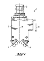
- the overcurrent protection switch 1 has a push button as the actuating element 2 for manual activation or triggering.
- the main terminal lugs 4 for wiring the main contacts 5 protrude from its insulating housing 3, and the add-on housing 6 with the inserted signal contact point is integrally formed on the overcurrent protection switch 1.
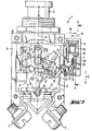
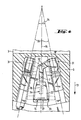
- the signal contact lever 15 shown in FIGS. 2 and 3 represents the connecting link between the toggle lever 8 and the signal contact point 7. Its stop arm 16 projects into the main switching chamber 17 formed by the insulating housing 3 and is there there by means of a stop projection attached to the joint-side end of the actuating arm 12 18 acted upon in the on position of the toggle lever 8. The stop projection 18 projects beyond the actuating arm 12 in the buckling direction 19 of the toggle lever 8 and its stop side is designed as a convex sliding step 20. This, together with the stop arm 16 of the signal contact lever 15 which is inclined towards the main connection contacts 5, ensures low friction forces to be overcome during the switch-on process.
- the contact spring 24 is U-shaped, the two U-legs 26 running parallel to the fixed contact 25 and to the direction of the housing depth 13.
- the U-connecting web 28 of the contact spring 24 faces the horizontal leg 27 of the contact arm 22, the vertical leg 29 of the contact arm 22 acts on the fixed-contact-side U-leg 26 of the contact spring 24 designed as a movement contact and opens the signal contact point 7 in the contact opening direction 30 facing the main switching chamber 17 .
Landscapes
- Breakers (AREA)
Applications Claiming Priority (3)
| Application Number | Priority Date | Filing Date | Title |
|---|---|---|---|
| DE8423098U DE8423098U1 (de) | 1984-08-03 | 1984-08-03 | Ein- oder mehrpoliger Überstromschutzschalter mit integrierter Signalkontaktstelle |
| DE3428637A DE3428637C1 (de) | 1984-08-03 | 1984-08-03 | Ein- oder mehrpoliger UEberstromschutzschalter mit integrierter Signalkontaktstelle |
| DE3428637 | 1984-08-03 |
Publications (3)
| Publication Number | Publication Date |
|---|---|
| EP0172374A2 true EP0172374A2 (fr) | 1986-02-26 |
| EP0172374A3 EP0172374A3 (en) | 1987-09-16 |
| EP0172374B1 EP0172374B1 (fr) | 1990-04-18 |
Family
ID=25823544
Family Applications (1)
| Application Number | Title | Priority Date | Filing Date |
|---|---|---|---|
| EP85108334A Expired - Lifetime EP0172374B1 (fr) | 1984-08-03 | 1985-07-05 | Disjoncteur uni- ou multipolaire avec contact de signalisation intégré |
Country Status (3)
| Country | Link |
|---|---|
| US (1) | US4612528A (fr) |
| EP (1) | EP0172374B1 (fr) |
| DE (2) | DE3428637C1 (fr) |
Cited By (1)
| Publication number | Priority date | Publication date | Assignee | Title |
|---|---|---|---|---|
| EP0434338A2 (fr) * | 1989-12-19 | 1991-06-26 | Texas Instruments Incorporated | Disjoncteur avec commutateur auxiliaire indicateur de l'état |
Families Citing this family (6)
| Publication number | Priority date | Publication date | Assignee | Title |
|---|---|---|---|---|
| US4837545A (en) * | 1987-04-02 | 1989-06-06 | Texas Instruments Incorporated | Miniature circuit breaker with improved longevity |
| FR2679698B1 (fr) * | 1991-07-25 | 1995-03-17 | Sextant Avionique | Dispositif de signalisation de declenchement d'un disjoncteur. |
| US6542061B2 (en) * | 2001-04-16 | 2003-04-01 | Cathy D. Santa Cruz | Indicator light for use in combination with an electrical circuit protector or fuse |
| KR101759601B1 (ko) * | 2015-12-28 | 2017-07-31 | 엘에스산전 주식회사 | 기중 차단기용 지연시간 발생장치 |
| EP3455869B1 (fr) | 2016-05-11 | 2023-08-23 | Safran Electrical & Power | Disjoncteur ayant une prise insérée à la force |
| CN109686625B (zh) * | 2018-12-28 | 2024-05-07 | 浙江正泰电器股份有限公司 | 小型断路器 |
Citations (5)
| Publication number | Priority date | Publication date | Assignee | Title |
|---|---|---|---|---|
| GB540338A (en) * | 1939-06-09 | 1941-10-14 | Igranic Electric Co Ltd | Improvements in or relating to auxiliary switches for electromagnetic contactors andthe like |
| DE875681C (de) * | 1942-03-17 | 1953-05-04 | Siemens Ag | Selbstschalter mit Handschaltung und UEberstromausloesung |
| US3602852A (en) * | 1970-06-05 | 1971-08-31 | Wood Electric Corp | Case assembly for circuit breakers |
| FR2112237A1 (fr) * | 1970-10-01 | 1972-06-16 | Heinemann Electric Co | |
| FR2224855A1 (fr) * | 1973-04-05 | 1974-10-31 | Cutler Hammer World Trade Inc |
Family Cites Families (6)
| Publication number | Priority date | Publication date | Assignee | Title |
|---|---|---|---|---|
| BE449931A (fr) * | 1942-03-17 | |||
| DE1061418B (de) * | 1956-09-15 | 1959-07-16 | Siemens Ag | Elektrischer, mit Kippbetaetigungsgriff versehener Schalter, insbesondere Leitungsschutzschalter |
| US3593235A (en) * | 1969-12-02 | 1971-07-13 | Heinemann Electric Co | Linearly operated circuit breaker |
| DE7009018U (de) * | 1970-03-12 | 1970-06-18 | Bbc Brown Boveri & Cie | Installationsselbstschalter mit hilfskontakt. |
| DE2123765B1 (de) * | 1971-05-13 | 1972-05-31 | Ellenberger & Poensgen | Dr]ckknopfbet[tigter ]berstromschalter |
| US4330772A (en) * | 1980-05-02 | 1982-05-18 | Eaton Corporation | Pushbutton circuit breaker switch |
-
1984
- 1984-08-03 DE DE3428637A patent/DE3428637C1/de not_active Expired
- 1984-08-03 DE DE8423098U patent/DE8423098U1/de not_active Expired
-
1985
- 1985-07-05 EP EP85108334A patent/EP0172374B1/fr not_active Expired - Lifetime
- 1985-07-10 US US06/753,630 patent/US4612528A/en not_active Expired - Lifetime
Patent Citations (5)
| Publication number | Priority date | Publication date | Assignee | Title |
|---|---|---|---|---|
| GB540338A (en) * | 1939-06-09 | 1941-10-14 | Igranic Electric Co Ltd | Improvements in or relating to auxiliary switches for electromagnetic contactors andthe like |
| DE875681C (de) * | 1942-03-17 | 1953-05-04 | Siemens Ag | Selbstschalter mit Handschaltung und UEberstromausloesung |
| US3602852A (en) * | 1970-06-05 | 1971-08-31 | Wood Electric Corp | Case assembly for circuit breakers |
| FR2112237A1 (fr) * | 1970-10-01 | 1972-06-16 | Heinemann Electric Co | |
| FR2224855A1 (fr) * | 1973-04-05 | 1974-10-31 | Cutler Hammer World Trade Inc |
Cited By (2)
| Publication number | Priority date | Publication date | Assignee | Title |
|---|---|---|---|---|
| EP0434338A2 (fr) * | 1989-12-19 | 1991-06-26 | Texas Instruments Incorporated | Disjoncteur avec commutateur auxiliaire indicateur de l'état |
| EP0434338A3 (en) * | 1989-12-19 | 1991-12-27 | Texas Instruments Incorporated | Circuit breaker with auxiliary status indicating switch |
Also Published As
| Publication number | Publication date |
|---|---|
| EP0172374B1 (fr) | 1990-04-18 |
| EP0172374A3 (en) | 1987-09-16 |
| DE3428637C1 (de) | 1985-11-21 |
| US4612528A (en) | 1986-09-16 |
| DE8423098U1 (de) | 1986-08-21 |
Similar Documents
| Publication | Publication Date | Title |
|---|---|---|
| DE670790C (de) | Thermisch wirkender Selbstschalter | |
| EP0680065B1 (fr) | Disjoncteur de protection de surcharge | |
| EP0222181B1 (fr) | Disjoncteur de surintensité | |
| EP0303965B1 (fr) | Appareil de commutation électrique | |
| EP0172374B1 (fr) | Disjoncteur uni- ou multipolaire avec contact de signalisation intégré | |
| DE7321781U (de) | Mehrphasenrelais zum Steuern von Schaltschutzen | |
| EP0111662A1 (fr) | Interrupteur électrique | |
| DE2804647C2 (de) | Elektrischer Dreiphasen-Überlastschalter | |
| EP0299291B1 (fr) | Disjoncteur de ligne | |
| EP0391086A1 (fr) | Dispositeur de protection à courant excessif commandé par un bouton-poussoir | |
| DE10216439A1 (de) | Hilfsschalter | |
| DE19703977C1 (de) | Schaltgerät mit Schnelleinschaltung | |
| EP0279363A2 (fr) | Disjoncteur de protection pour courant de défaut | |
| EP0849759B1 (fr) | Appareil de coupure pour une installation électrique | |
| EP0147629B1 (fr) | Disjoncteur de protection | |
| DE2314332A1 (de) | Schnappschalter | |
| DE2915169C3 (de) | Hilfsschalter für Schutzschalter | |
| DE3038511A1 (de) | Ueberstromschutzschalter | |
| EP1037238B1 (fr) | Disjoncteur de surintensité | |
| WO2000067275A1 (fr) | Unite coupe-circuit pour declenchement multipolaire | |
| DE1095378B (de) | Schaltgeraet mit thermischer Ausloesung | |
| EP0851449B1 (fr) | Appareil de commutation pour une installation électrique | |
| CH634689A5 (de) | Leitungsschutzschalter in flachbauweise mit elektromagnetischer, thermischer und manueller ausloesung. | |
| EP0114245A1 (fr) | Procédé pour protéger un réseau basse tension sectionné et dispositif de commutation pour sa réalisation | |
| DE3542623C2 (fr) |
Legal Events
| Date | Code | Title | Description |
|---|---|---|---|
| PUAI | Public reference made under article 153(3) epc to a published international application that has entered the european phase |
Free format text: ORIGINAL CODE: 0009012 |
|
| AK | Designated contracting states |
Designated state(s): CH DE FR GB IT LI SE |
|
| ITCL | It: translation for ep claims filed |
Representative=s name: RICCARDI SERGIO & CO. |
|
| EL | Fr: translation of claims filed | ||
| PUAL | Search report despatched |
Free format text: ORIGINAL CODE: 0009013 |
|
| AK | Designated contracting states |
Kind code of ref document: A3 Designated state(s): CH DE FR GB IT LI SE |
|
| 17P | Request for examination filed |
Effective date: 19871029 |
|
| 17Q | First examination report despatched |
Effective date: 19891002 |
|
| GRAA | (expected) grant |
Free format text: ORIGINAL CODE: 0009210 |
|
| AK | Designated contracting states |
Kind code of ref document: B1 Designated state(s): CH DE FR GB IT LI SE |
|
| REF | Corresponds to: |
Ref document number: 3577249 Country of ref document: DE Date of ref document: 19900523 |
|
| GBT | Gb: translation of ep patent filed (gb section 77(6)(a)/1977) | ||
| ITF | It: translation for a ep patent filed |
Owner name: UFFICIO BREVETTI RICCARDI & C. |
|
| ET | Fr: translation filed | ||
| PLBE | No opposition filed within time limit |
Free format text: ORIGINAL CODE: 0009261 |
|
| STAA | Information on the status of an ep patent application or granted ep patent |
Free format text: STATUS: NO OPPOSITION FILED WITHIN TIME LIMIT |
|
| 26N | No opposition filed | ||
| ITTA | It: last paid annual fee | ||
| EAL | Se: european patent in force in sweden |
Ref document number: 85108334.5 |
|
| PGFP | Annual fee paid to national office [announced via postgrant information from national office to epo] |
Ref country code: GB Payment date: 20010612 Year of fee payment: 17 |
|
| PGFP | Annual fee paid to national office [announced via postgrant information from national office to epo] |
Ref country code: FR Payment date: 20010717 Year of fee payment: 17 |
|
| PGFP | Annual fee paid to national office [announced via postgrant information from national office to epo] |
Ref country code: SE Payment date: 20010723 Year of fee payment: 17 Ref country code: CH Payment date: 20010723 Year of fee payment: 17 |
|
| REG | Reference to a national code |
Ref country code: GB Ref legal event code: IF02 |
|
| PG25 | Lapsed in a contracting state [announced via postgrant information from national office to epo] |
Ref country code: GB Free format text: LAPSE BECAUSE OF NON-PAYMENT OF DUE FEES Effective date: 20020705 |
|
| PG25 | Lapsed in a contracting state [announced via postgrant information from national office to epo] |
Ref country code: SE Free format text: LAPSE BECAUSE OF NON-PAYMENT OF DUE FEES Effective date: 20020706 |
|
| PG25 | Lapsed in a contracting state [announced via postgrant information from national office to epo] |
Ref country code: LI Free format text: LAPSE BECAUSE OF NON-PAYMENT OF DUE FEES Effective date: 20020731 Ref country code: CH Free format text: LAPSE BECAUSE OF NON-PAYMENT OF DUE FEES Effective date: 20020731 |
|
| GBPC | Gb: european patent ceased through non-payment of renewal fee |
Effective date: 20020705 |
|
| EUG | Se: european patent has lapsed | ||
| REG | Reference to a national code |
Ref country code: CH Ref legal event code: PL |
|
| PG25 | Lapsed in a contracting state [announced via postgrant information from national office to epo] |
Ref country code: FR Free format text: LAPSE BECAUSE OF NON-PAYMENT OF DUE FEES Effective date: 20030331 |
|
| REG | Reference to a national code |
Ref country code: FR Ref legal event code: ST |
|
| PGFP | Annual fee paid to national office [announced via postgrant information from national office to epo] |
Ref country code: DE Payment date: 20040923 Year of fee payment: 20 |