EP0172374A2 - Single or multiphase circuit breaker with integrated signalisation contact - Google Patents
Single or multiphase circuit breaker with integrated signalisation contact Download PDFInfo
- Publication number
- EP0172374A2 EP0172374A2 EP85108334A EP85108334A EP0172374A2 EP 0172374 A2 EP0172374 A2 EP 0172374A2 EP 85108334 A EP85108334 A EP 85108334A EP 85108334 A EP85108334 A EP 85108334A EP 0172374 A2 EP0172374 A2 EP 0172374A2
- Authority
- EP
- European Patent Office
- Prior art keywords
- contact
- arm
- lever
- overcurrent protection
- protection switch
- Prior art date
- Legal status (The legal status is an assumption and is not a legal conclusion. Google has not performed a legal analysis and makes no representation as to the accuracy of the status listed.)
- Granted
Links
Images

Classifications
-
- H—ELECTRICITY
- H01—ELECTRIC ELEMENTS
- H01H—ELECTRIC SWITCHES; RELAYS; SELECTORS; EMERGENCY PROTECTIVE DEVICES
- H01H71/00—Details of the protective switches or relays covered by groups H01H73/00 - H01H83/00
- H01H71/08—Terminals; Connections
-
- H—ELECTRICITY
- H01—ELECTRIC ELEMENTS
- H01H—ELECTRIC SWITCHES; RELAYS; SELECTORS; EMERGENCY PROTECTIVE DEVICES
- H01H71/00—Details of the protective switches or relays covered by groups H01H73/00 - H01H83/00
- H01H71/10—Operating or release mechanisms
- H01H71/12—Automatic release mechanisms with or without manual release
- H01H71/46—Automatic release mechanisms with or without manual release having means for operating auxiliary contacts additional to the main contacts
Definitions
- the invention relates to an overcurrent protection switch of the type described in the preamble of claim 1, as is known for example from German patent 21 23 765.
- a disadvantage of this conventional single-pole or multi-pole overcurrent protection switch is the lack of a signal contact point, which provides information about the current status of the overcurrent protection switch by means of a signal circuit connected to it.
- a control box with a large number of so-called on-board circuit breakers may be mentioned here, in which it would be difficult to find the source of the error quickly and accurately without the associated signal lamps indicating a trip.
- the characterizing features of claim 5 describe a particularly advantageous design of the overcurrent protection switch designed according to the invention.
- the signal contact point is securely closed by the U-leg of the contact spring, which has a high spring force, when the L-shaped lever is not influenced in the off position of the overcurrent protection switch.
- the add-on housing Due to the special shape and direction of its components described, the add-on housing also has a high degree of compactness, and can be easily installed in existing switch boxes of conventional design.
- both the main connections and the signal contact connections can be brought from the same side from behind to the housing, with the rearward opening, angular arrangement of the metal sockets for the electrical leads for the signal contact point can easily be passed to both sides of the main connection wires and connected to the corresponding metal sockets.
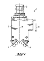
- the overcurrent protection switch 1 has a push button as the actuating element 2 for manual activation or triggering.
- the main terminal lugs 4 for wiring the main contacts 5 protrude from its insulating housing 3, and the add-on housing 6 with the inserted signal contact point is integrally formed on the overcurrent protection switch 1.
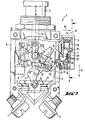
- the signal contact lever 15 shown in FIGS. 2 and 3 represents the connecting link between the toggle lever 8 and the signal contact point 7. Its stop arm 16 projects into the main switching chamber 17 formed by the insulating housing 3 and is there there by means of a stop projection attached to the joint-side end of the actuating arm 12 18 acted upon in the on position of the toggle lever 8. The stop projection 18 projects beyond the actuating arm 12 in the buckling direction 19 of the toggle lever 8 and its stop side is designed as a convex sliding step 20. This, together with the stop arm 16 of the signal contact lever 15 which is inclined towards the main connection contacts 5, ensures low friction forces to be overcome during the switch-on process.
- the contact spring 24 is U-shaped, the two U-legs 26 running parallel to the fixed contact 25 and to the direction of the housing depth 13.
- the U-connecting web 28 of the contact spring 24 faces the horizontal leg 27 of the contact arm 22, the vertical leg 29 of the contact arm 22 acts on the fixed-contact-side U-leg 26 of the contact spring 24 designed as a movement contact and opens the signal contact point 7 in the contact opening direction 30 facing the main switching chamber 17 .
Abstract
Ein ein- oder mehrpoliger, von Hand oder thermisch betätigbarer Überstromschutzschalter (1) enthält in seiner Hauptschaltkammer einen als Wirkverbindung zwischen einem Betätigungselement (2) und einer Kontaktbrücke (11) fungierenden Kniehebel (8), der aus einem Betätigungsarm (12) und einem Hauptkontaktarm (9) besteht. Die dem Kniegelenk (8') abgewandten Enden vom Betätigungsarm (12) und Hauptkontaktarm (9) sind mittels Drehgelenken (10) am Betätigungselement (2) und der Kontaktbrucke (11) angelenkt. In allen Bewegungsstellungen zwischen der die Ausschaltstellung bildenden Knick- und der die arretierte Einschaltstellung bildenden Streckstellung des Kniehebels (8) liegen diese Anlenkpunkte auf der in Richtung der Gehäusetiefe (13) verlaufenden Mittellängsachse (14) des Isoliergehäuses (3). Der Betätigungsarm (12) beaufschlagt in Kniehebelstreckstellung mittels eines an sein gelenkseitiges Ende angesetzten Anschlagvorsprunges (18) einen doppelarmigen Signalkontakthebel. Dessen Anschlagarm (16) ragt in die Hauptschaltkammer (17), dessen anderer Kontaktarm (22) steht in ein an das Isoliergehäuse (3) engesetztes, eine Signalkontaktstelle (7) enthaltendes Anbaugehäuse (6) hinein. Dabei beaufschlagt der Kontaktarm (22) eine Kontaktfeder (24) und öffnet oder schließt dadurch je nach der von der Stellung des Anschlagvorsprunges (18) abhängigen Schwenkstellung die aus einer Kontaktfeder (24) und einem Festkontakt (25) bestehende Hilfs- oder Signalkontaktstelle (7).A single-pole or multi-pole, manually or thermally actuable overcurrent protection switch (1) contains in its main switching chamber a toggle lever (8) which acts as an active connection between an actuating element (2) and a contact bridge (11) and which consists of an actuating arm (12) and a main contact arm (9) exists. The ends of the actuating arm (12) and main contact arm (9) facing away from the knee joint (8 ') are articulated on the actuating element (2) and the contact bridge (11) by means of rotary joints (10). In all movement positions between the kink lever (8) forming the switch-off position and the extended position forming the locked switch-on position, these articulation points lie on the central longitudinal axis (14) of the insulating housing (3) running in the direction of the housing depth (13). The actuating arm (12) acts on a double-armed signal contact lever in the extended toggle lever position by means of a stop projection (18) attached to its joint-side end. Its stop arm (16) protrudes into the main switching chamber (17), the other contact arm (22) of which extends into an attachment housing (6) which is inserted into the insulating housing (3) and contains a signal contact point (7). The contact arm (22) acts on a contact spring (24) and thereby opens or closes the auxiliary or signal contact point (7) consisting of a contact spring (24) and a fixed contact (25) depending on the pivot position depending on the position of the stop projection (18) ).
Description
Die Erfindung bezieht sich auf einen Überstromschutzschalter der im Oberbegriff des Anspruches 1 beschriebenen Art, wie er beispielsweise aus der deutschen Patentschrift 21 23 765 bekannt ist.The invention relates to an overcurrent protection switch of the type described in the preamble of claim 1, as is known for example from German patent 21 23 765.
Der bekannte druckknopfbetätigte Überstromschutzschalter ist mit einer Kontaktbrücke ve-rsehen, die mittels eines Kniehebels mit dem Betätigungselement in Verbindung steht. Dieser in einer von einem Isoliergehäuse gebildeten Hauptschaltkammer einliegende Kniehebel wird von einem Betätigungsarm und einem Hauptkontaktarm gebildet. Die dem Kniegelenk abgewandten Enden der beiden Arme sind mittels Drehgelenken am Betätigungselement bzw. der Kontaktbrücke angelenkt. Die Anlenkpunkte liegen in allen Bewegungsstellungen zwischen der die Ausschaltstellung bildenden Knick- und der die arretierte Einschaltstellung bildenden angenäherten Streckstellung des Kniehebels auf der in Richtung der Gehäusetiefe verlaufenden Mittellängsachse des Isoliergehäuses. Dabei schiebt eine im Bereich des Kniegelenks angreifende Feder mit ihrer Druckkraft den Betätigungsarm vom Hauptkontaktarm weg. Ist die Einschaltstellung erreicht, wird der Kniehebel von einer Sperrklinke arretiert, die durch Hand oder thermische Betätigung auslösbar ist. Durch diese, in der obengenannten Patentschrift näher beschriebene Konstruktion des Überstromschutzschalters werden mit einfachen, raumsparenden Mitteln eine Momenteinschaltung, sowie eine Hand-, eine äußerst schnelle thermische und eine Freiauslösung erreicht.The known push-button operated overcurrent protection switch is provided with a contact bridge which is connected to the actuating element by means of a toggle lever. This toggle lever lying in a main switching chamber formed by an insulating housing is formed by an actuating arm and a main contact arm. The ends of the two arms facing away from the knee joint are articulated on the actuating element or the contact bridge by means of rotary joints. The articulation points lie in all movement positions between the bent position forming the switch-off position and the approximate extended position of the toggle lever forming the locked switch-on position on the central longitudinal axis of the insulating housing which runs in the direction of the housing depth. A spring engaging in the area of the knee joint pushes the actuating arm away from the main contact arm with its compressive force. Once the switch-on position has been reached, the toggle lever is locked by a pawl that can be actuated by hand or thermal actuation can be triggered. Through this construction of the overcurrent protection switch, which is described in more detail in the abovementioned patent specification, a torque switch-on as well as manual, extremely rapid thermal and free tripping are achieved with simple, space-saving means.
Eine ähnliche Kniehebelkonstruktion mit zugeordneten Hilfshebeln ist Gegenstand der deutschen Patentschrift 25 07 454. Dabei wird durch die über eine gemeinsame Achse in Verbindung stehenden Hilfshebel der den mehrpoligen Schalter bildenden einpoligen Überstromschutzschalter eine im wesentlichen gleichzeitige, allpolige Auslösung ohne höhere, die Schaltzeit beeinflußende mechanische Kräfte als bei der einpoligen Auslösung erzielt.A similar toggle lever construction with associated auxiliary levers is the subject of
Ein Nachteil dieser herkömmlichen ein- bzw. mehrpoligen Überstromschutzschalter ist das Fehlen einer Signalkontaktstelle, die mittels eines daran angeschlossenen Signalkreises Auskunft über den momentanen Status des Überstromschutzschalters gibt. Beispielsweise sei hier ein Schaltkasten mit einer Vielzahl von sogenannten Bordnetzschutzschaltern genannt, bei dem es ohne zugeordnete, eine Auslösung anzeigenden Signallämpchen schwer möglich wäre, die Fehlerquelle schnell und zielsicher zu finden.A disadvantage of this conventional single-pole or multi-pole overcurrent protection switch is the lack of a signal contact point, which provides information about the current status of the overcurrent protection switch by means of a signal circuit connected to it. For example, a control box with a large number of so-called on-board circuit breakers may be mentioned here, in which it would be difficult to find the source of the error quickly and accurately without the associated signal lamps indicating a trip.
Einen solchen Überstromschutzschalter mit einer Signalkontaktstelle beschreibt CH-PS 233 959, in der die Kontaktbrücke während ihres Schließens eine in ihren Verschiebeweg hineinstehende Isolierstofftrennwand in Kontaktschließrichtung verschiebt. Das signalkontaktseitige Freiende dieser Wand steuert den beweglichen Hilfskontakt der Signalkontaktstelle. Nachteilig bei dieser Konstruktion ist die Tatsache, daß die Rückstellkraft der Hilfskontaktfeder direkt gegen die Schließrichtung der Kontaktbrücke wirkt. Dadurch wird der erzielbare Kontaktdruck und damit die Stromleitfähigkeit des Hauptkontaktes reduziert. Außerdem wird durch die Rückstellkraft die Reibung zwischen den Einzelteilen der Verklinkungsstelle des Kniehebels erhöht, was zu einer Erhöhung der notwendigen Auslösekraft führt. Dadurch erhöht sich die Auslösezeit bei herkömmlichen Überstromschutzschaltern dieser Art, was die Schutzwirkung naturgemäß herabsetzt.Such an overcurrent protection switch with a signal contact point is described in CH-PS 233 959, in which the contact bridge, during its closing, shifts an insulating material partition wall which is in its displacement path in the contact closing direction. The free end of this wall on the signal contact side controls the movable auxiliary contact of the signal contact point. A disadvantage of this construction is the fact that the restoring force the auxiliary contact spring acts directly against the closing direction of the contact bridge. This reduces the contact pressure that can be achieved and thus the current conductivity of the main contact. In addition, the restoring force increases the friction between the individual parts of the latching point of the toggle lever, which leads to an increase in the necessary release force. This increases the tripping time for conventional overcurrent protection switches of this type, which naturally reduces the protective effect.
Der Erfindung liegt die Aufgabe zugrunde, einen Überstromschutzschalter der eingangs beschriebenen Art so auszubilden, daß er eine Signalkontaktstelle bereitstellt, deren Kontaktgabe eindeutig mit der Ein- bzw. Ausschaltstellung des Überstromschutzschalters gekoppelt ist, ohne jedoch eine Verschlechterung der Kontaktdruck- und Auslösecharakteristik in Kauf nehmen zu müssen. Diese Aufgabe wird gemäß den kennzeichnenden Merkmalen des Anspruches 1 dadurch gelöst, daß der Betätigungsarm des Kniehebels mit zunehmender Kniehebelstreckung mittels eines an sein gelenkseitiges Ende angesetzten Anschlagvorsprunges einen doppelarmigen Signalkontakthebel zunehmend auslenkt. Dessen Anschlagarm ragt in die Hauptschaltkammer, dessen anderer Kontaktarm liegt in einem an das Isoliergehäuse angesetzten, einen Signalkontakt enthaltenden Anbaugehäuse. Dieser Kontaktarm beaufschlagt eine Kontaktfeder, die zusammen mit einem Festkontakt die Hilfs- oder Signalkontaktstelle bildet. Die Auslösecharakteristik des Überstromschutzschalters wird durch die im kennzeichnenden Teil beschriebene Bauform bedingt im wesentlichen nicht verändert, da beim Erfindungsgegenstand gänzlich andere Hebelverhältnisse herrschen, als bei herkömmlichen Überstromschutzschaltern nach dem Stande der Technik. Damit bleibt der übliche Kontaktdruck erhalten und die Auslösezeit wird vorteilhafterweise nicht erhöht, obwohl der Kniehebel die zusätzliche Funktion der Betätigung einer Signalkontaktstelle erfüllt. Deren offener oder geschlossener Status ist abhängig von der jeweiligen Schwenkstellung des Signalkontakthebels, die wiederum durch die Stellung des an den Betätigungsarm angesetzten Anschlagvorsprunges in der Hauptschaltkammer bestimmt wird. Wird der Überstromschutzschalter beispielsweise durch die Streckung des Kniehebels in Einschaltstellung gebracht, lenkt der Anschlagvorsprung den Signalkontakthebel aus, der durch seine Schwenkbewegung die Kontaktfeder der Signalkontaktstelle vom Festkontakt zunehmend abhebt und damit beispielsweise einen Stromkreis für ein Signallämpchen unterbricht. Damit ist eine eindeutige Zuordnung "Überstromschutzschalter ein - Signalkontakt aus" und umgekehrt gegeben. Genausogut kann mit wenigen baulichen Veränderungen des Signalkontakthebels und der Signalkontaktstelle eine eindeutige Zuordnung "Überstromschutzschalter ein - Signalkontakt ein" und umgekehrt geschaffen werden.The invention has for its object to provide an overcurrent protection switch of the type described in such a way that it provides a signal contact point, the contact of which is clearly coupled to the on or off position of the overcurrent protection switch, but without accepting a deterioration in the contact pressure and tripping characteristics have to. This object is achieved in accordance with the characterizing features of claim 1 in that the actuating arm of the toggle lever increasingly deflects a double-armed signal contact lever as the toggle lever extension increases by means of a stop projection attached to its joint-side end. Its stop arm protrudes into the main switching chamber, the other contact arm of which lies in an attachment housing attached to the insulating housing and containing a signal contact. This contact arm acts on a contact spring which, together with a fixed contact, forms the auxiliary or signal contact point. The tripping characteristic of the overcurrent protection switch is essentially not changed due to the design described in the characterizing part, since the subject matter of the invention is entirely different from that of conventional overcurrent protection switches according to the prior art. This leaves the usual contact pressure hold and the triggering time is advantageously not increased, although the toggle lever fulfills the additional function of actuating a signal contact point. Their open or closed status depends on the respective swivel position of the signal contact lever, which in turn is determined by the position of the stop projection attached to the actuating arm in the main switching chamber. If, for example, the overcurrent protection switch is brought into the switched-on position by the extension of the toggle lever, the stop projection deflects the signal contact lever, which increasingly pivots the contact spring of the signal contact point from the fixed contact due to its pivoting movement and thus interrupts, for example, a circuit for a signal lamp. This provides a clear assignment of "overcurrent protection switch on - signal contact off" and vice versa. With just a few structural changes to the signal contact lever and the signal contact point, an unambiguous assignment "overcurrent protection switch on - signal contact on" and vice versa can be created.
Die das kennzeichnende Merkmal des Anspruches 2 bedingende Gleichebigkeit der Bewegungsebenen von Kniehebel und Signalkontakthebel ermöglicht einen besonders einfachen, mechanischen Aufbau des Überstromschutzschalters, da keine aufwendigen mechanischen Bauelemente zum Einsatz kommen müssen, die eine mechanische Bewegung aus einer Ebene in eine andere überführen.The characteristic feature of
Das kennzeichnende Merkmal des Anspruches 3 beschreibt eine besonders einfache Bauform für das Anbaugehäuse des Signalkontaktes, die besonders fertigungsrationell und wirtschaftlich hergestellt werden kann und einem schnellen Zusammenbau des erfindungsgemäß ausgestalteten Überstromschutzschalters dienlich ist.The characterizing feature of
Durch das Kennzeichnungsmerkmal des Anspruches 4 wird eine etwa gleiche Hebelarmlänge des Signalkontakthebels erreicht, wodurch die auftretenden Hebelkräfte und -wege minimalisiert werden können.The characteristic feature of
Durch die kennzeichnenden Merkmale des Anspruches 5 wird eine besonders vorteilhafte Bauform des erfindungsgemäß ausgestalteten Überstromschutzschalters beschrieben. Z.B. wird die Signalkontaktstelle durch die eine hohe Federkraft aufweisenden U-Schenkel der Kontaktfeder sicher geschlossen, wenn der L-förmige Hebel in Ausschalt-Stellung des Überstromschutzschalters nicht beeinflußt wird. Durch die beschriebene spezielle Form und Richtung seiner Bauelemente weist das Anbaugehäuse auch ein hohes Maß an Kompaktheit auf, ein problemloser Einbau in vorhandene Schaltkästen herkömmlicher Bauart ist möglich. Diese Tatsache wird durch das kennzeichnende Merkmal des Anspruches 6 noch unterstützt, da dadurch sowohl die Hauptanschlüsse als auch die Signalkontaktanschlüsse von derselben Seite von hinten an das Gehäuse herangeführt werden können, wobei durch die sich nach hinten öffnende, winklige Anordnung der Metallbuchsen die elektrischen Zuleitungen für die Signalkontaktstelle problemlos zu beiden Seiten der Hauptanschlußdrähte vorbeigeführt und an den entsprechenden Metallbuchsen angeschlossen werden können.The characterizing features of
Durch die kennzeichnenden Merkmale der Ansprüche 7-10 wird eine Bauform des erfindungsgemäßen Überstromschutzschalters erreicht, bei der die für die Betätigung des zusätzlichen Signalkontakthebels notwendigen mechanischen Kräfte besonders niedrig werden. Im Zusammenspiel mit dem Kennzeichnungsmerkmal des Anspruches 5 z.B. unterstützt die durch die Federkraft der U-förmigen Kontaktfeder erzeugte Rückschwenkbewegung des Signalkontakthebels sogar die Aufreißbewegung des Kniehebels. Der schräg in die Hauptkontaktschaltkammer ragende Arm des Signalkontakthebels bedingt zusammen mit dem als konvexe Gleitstufe ausgebildeten Anschlagvorsprung ein reibungsarmes Aufgleiten dieses Bauelements beim Einschaltvorgang. Die Auslösecharakteristik des Überstromschutzschalters wird durch die im Kennzeichnungsmerkmal des Anspruches 11 beschriebene Bauform bedingt weiter verbessert. Da die Kraftwirkungslinie des vom Anschlagarm auf den Anschlagvorsprung ausgeübten Reaktionsdruckes durch das betätigungsseitige Drehlager des Betätigungsarmes verläuft, wirken in Einschaltstellung auf die Kniehebelanordnung keine zusätzlichen Drehmomente.Due to the characterizing features of claims 7-10, a design of the overcurrent protection switch according to the invention is achieved in which the mechanical forces necessary for actuating the additional signal contact lever become particularly low. In cooperation with the characterizing feature of
Ein Ausführungsbeispiel der Erfindung ist in den Fig. 1-4 dargestellt. Es zeigen:
- Fig. 1 eine Gesamt-Seitenansicht eines Überstromschutzschalters der erfindungsgemäßen Art,
- Fig. 2 eine vergrößerte Seitenansicht des Überstromschutzschalters in teilweise geöffneter Form in Einschaltstellung,
- Fig. 3 eine Seitenansicht analog Fig. 2 in Ausschalt- stellung,
- Fig. 4 eine Seitenansicht der Bewegungsteile im Signalkontakt-Anbaugehäuse entsprechend der Linie A-A in Fig. 3
- 1 is an overall side view of an overcurrent protection switch of the type according to the invention,
- 2 is an enlarged side view of the overcurrent protection switch in a partially open form in the on position,
- F ig. 3 shows a side view analogous to FIG. 2 in the switched-off position,
- FIG. 4 shows a side view of the moving parts in the signal contact attachment housing along the line AA in FIG. 3
Wie aus Fig. 1 ersichtlich, weist der Überstromschutzschalter 1 für die Handeinschaltung bzw. Handauslösung einen Druckknopf als Betätigungselement 2 auf. Aus seinem Isoliergehäuse 3 ragen die Hauptanschlußfahnen 4 zur Beschaltung der Hauptkontakte 5, einstückig an den Überstromschutzschalter 1 angeformt ist das Anbaugehäuse 6 mit der einliegenden Signalkontaktstelle .As can be seen from FIG. 1, the overcurrent protection switch 1 has a push button as the actuating
In Fig. 2 ist der Kniehebel 8 gezeichnet. In dieser Einschaltstellung verbindet die am unteren Ende des Hauptkontaktarmes 9 mittels Drehgelenk 10 angelenkte Kontaktbrücke 11 die beiden Hauptkontakte 5. Der mit dem Hauptkontaktarm 9 über eine Stift-Schlitz-Konstruktion des Kniegelenks 8' verbundene Betätigungsarm 12 ist ebenfalls mittels eines Drehgelenks 10 über ein Kuppelelement 2a mit dem Betätigungselement 2 verbunden. In allen Bewegungsstellungen des Kniehebels zwischen der Einschaltstellung (entsprechend Fig. 2) und der Ausschaltstellung (entsprechend Fig. 3) fällt die Verbindungslinie zwischen den beiden Drehachsen 10 des Kniehebels 8 mit der in Richtung der Gehäusetiefe 13 verlaufenden Mittellängsachse 14 des Isoliergehäuses 3 zusammen.2, the
Der in den Fig. 2 und 3 gezeichnete Signalkontakthebel 15 stellt das Verbindungsglied zwischen dem Kniehebel 8 und der Signalkontaktstelle 7 dar. Sein Anschlagarm 16 ragt in die vom Isoliergehäuse 3 gebildete Hauptschaltkammer 17 und wird dort mittels eines an das gelenkseitige Ende des Betätigungsarmes 12 angesetzten Anschlagvorsprunges 18 in Einschaltstellung des Kniehebels 8 beaufschlagt. Der Anschlagvorsprung 18 steht in Ausknickrichtung 19 des Kniehebels 8 über den Betätigungsarm 12 hinaus und seine Anschlagseite ist als konvexe Gleitstufe 20 ausgebildet. Diese gewährleistet zusammen mit dem schräg in Richtung auf die Hauptanschlußkontakte 5 geneigten Anschlagarm 16 des Signalkontakthebels 15 geringe beim Einschaltvorgang zu überwindende Reibungskräfte. In Streckstellung des Kniehebels 8 lenkt der Anschlagvorsprung 18 den Signalkontakthebel 15 derart aus, daß die Kraftwirkungslinie 21 des vom Anschlagarm 16 auf den Anschlagvorsprung 18 ausgeübten Reaktionsdruckes durch das betätigungsseitige Drehgelenk 10 des Betätigungsarmes 12 verläuft. Dadurch wird die Auslösecharakteristik des Überstromschutzschalters nicht negativ beeinflußt, d.h. die erfindungsgemäßen Überstromschutzschalter mit integriertem Signalkontaktanbau können den Grundaufbau der herkömmlichen Überstromschutzschalter verwenden. Der L-förmige Kontaktarm 22 des schwenkbar um die seine Drehachse 23 gelagerten Signalkontakthebel 15 hintergreift im Anbaugehäuse 6 die U-förmige Kontaktfeder 24. Diese bildet zusammen mit dem Festkontakt 25 die Signalkontaktstelle 7, die je nach der Schwenkstellung des Signalkontakthebels 15 geöffnet oder geschlossen ist.The
Wie aus den Fig. 2 und 3 zu entnehmen ist, ist die Kontaktfeder 24 U-förmig ausgebildet, wobei die beiden U-Schenkel 26 parallel zum Festkontakt 25 und zur Richtung der Gehäusetiefe 13 verlaufen. Dem Horizontalschenkel 27 des Kontaktarmes 22 ist dabei der U-Verbindungssteg 28 der Kontaktfeder 24 zugewandt, der Vertikalschenkel 29 des Kontaktarmes 22 beaufschlagt den festkontaktseitigen U-Schenkel 26 der als Bewegungskontakt ausgeführten Kontaktfeder 24 und öffnet die Signalkontaktstelle 7 in der der Hauptschaltkammer 17 zugewandten Kontaktöffnungsrichtung 30.As can be seen from FIGS. 2 and 3, the
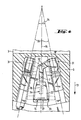
In Fig. 4 ist dargestellt, wie die Signalkontaktstelle 7 mit ihrer Kontaktfeder 24 und ihrem Festkontakt 25 über Metallbuchsen 31 elektrisch angeschlossen sind. Die elektrische Verbindung zwischen diesen Bauelementen 24,25,31 ist durch an die Kontaktfeder 24 bzw. an den Festkontakt 25 angeformte elektrisch leitende Verbindungsstücke 32 gewährleistet. Die Metallbuchsen 31 sind im Anbaugehäuse 6 beiderseits der Signalkontaktstelle 7 angeordnet und bilden mit ihren Achsen 33 einen sich in Richtung der Gehäusetiefe 13 öffnenden spitzen Winkel 34. Die von diesem aufgespannte Ebene liegt senkrecht zur Bewegungsebene des Signalkontakthebels 15, damit können die vier Anschlußkabel für die -9- Hauptkontakte 5 bzw. die Signalkontaktstelle 7 problemlos an den Überstromschutzschalter 1 herangeführt werden.FIG. 4 shows how the
- 1 Überstromschutzschalter1 overcurrent protection switch
- 2 Betätigungselement2 actuating element
- 2a Kuppelelement2a coupling element
- 3 Isoliergehäuse3 insulating housing
- 4 Hauptanschlußfahnen4 main connection flags
- 5 Hauptkontakt5 main contact
- 6 Anbaugehäuse6 extension housing
- 7 Signalkontaktstelle7 signal contact point
- 8 Kniehebel mit Kniegelenk 8'8 knee levers with knee joint 8 '
- 9 Hauptkontaktarm9 main contact arm
- 10 Drehgelenk10 swivel
- 11 Kontaktbrücke11 contact bridge
- 12 Betätigungsarm12 operating arm
- 13 Richtung d. Gehäusetiefe13 direction d. Case depth
- 14 Mittellängsachse14 central longitudinal axis
- 15 Signalkontakthebel15 signal contact lever
- 16 Anschlagarm16 stop arm
- 17 Hauptschaltkammer17 main control chamber
- 18 Anschlagvorsprung18 stop projection
- 19 Ausknickrichtung19 Buckling direction
- 20 Gleitstufe20 sliding step
- 21 Kraftwirkungslinie21 line of action of force
- 22 Kontaktarm22 contact arm
- 23 Drehachse23 axis of rotation
- 24 Kontaktfeder24 contact spring
- 25 Festkontakt25 fixed contact
- 26 U-Schenkel26 U-legs
- 27 Horizontalschenkel27 horizontal legs
- 28 U-Verbindungssteg28 U-connecting bridge
- 29 Vertikalschenkel29 vertical legs
- 30 Kontaktöffnungsrichtung30 contact opening direction
- 31 Metallbuchse31 metal bushing
- 32 Verbindungsstücke32 connectors
- 33 Achse d. Metallbuchse33 axis d. Metal bushing
- 34 Winkel34 angles
Claims (11)
dadurch gekennzeichnet,
characterized,
dadurch gekennzeichnet,
daß die Bewegungsebenen von Kniehebel (8) und Signalkontakthebel (15) gleichebig sind.2. Overcurrent protection switch according to claim 1,
characterized,
that the movement levels of toggle lever (8) and signal contact lever (15) are the same.
dadurch gekennzeichnet,
daß das Anbaugehäuse (6) einstückig in das Isoliergehäuse (3) der Hauptschaltkammer (17) integriert ist.3. Overcurrent protection switch according to claim 1,
characterized,
that the attachment housing (6) is integrated in one piece in the insulating housing (3) of the main switching chamber (17).
dadurch gekennzeichnet,
daß die Drehachse (23) des Signalkontakthebels (15) im Übergangsbereich zwischen dem Anbaugehäuse (6) und der Hauptschaltkammer (17) angeordnet ist.4. Overcurrent protection switch according to at least one of claims 1 to 3,
characterized,
that the axis of rotation (23) of the signal contact lever (15) is arranged in the transition region between the attachment housing (6) and the main switching chamber (17).
dadurch gekennzeichnet,
characterized,
dadurch gekennzeichnet,
characterized,
dadurch gekennzeichnet,
daß der Anschlagvorsprung (18) in Ausknickrichtung (19) des Kniehebels (8) über den Betätigungsarm (12) hinaussteht.7. Overcurrent protection switch according to one or more of the preceding claims,
characterized,
that the stop projection (18) in the buckling direction (19) of the toggle lever (8) projects beyond the actuating arm (12).
dadurch gekennzeichnet, daß die Anschlagseite des Anschlagvorsprunges (18) als konvexe Gleitstufe (20) ausgebildet ist.8. Overcurrent protection switch according to claim 7,
characterized in that the stop side of the stop projection (18) is designed as a convex sliding step (20).
dadurch gekennzeichnet, daß die Anschlagfläche des Anschlagarmes (16) des Signalkontakthebels (15) schräg in Richtung auf die Hauptkontakte (5) geneigt in die Hauptschaltkammer (17) ragt.9. Overcurrent protection switch according to one or more of the preceding claims,
characterized in that the stop surface of the stop arm (16) of the signal contact lever (15) protrudes obliquely into the main switching chamber (17) in the direction of the main contacts (5).
dadurch gekennzeichnet, daß die Anschlagfläche des Anschlagarmes (16) mit der Mittellängsachse (14) des Isoliergehäuses (3) einen sich in Richtung auf die Hauptkontakte (5) schließenden Winkel um 450 bildet.10. Overcurrent protection switch according to claim 9,
characterized in that the stop surface of the stop arm (16) with the central longitudinal axis (14) is formed of the insulating housing (3) comprises in the direction of the main contacts (5) closing angle about 45 0th
dadurch gekennzeichnet, daß in Streckstellung des Kniehebels (8) der Anschlagvorsprung (18) den Signalkontakthebel (15) gegen den Schließdruck der Kontaktfeder (24) auslenkend derart an der Anschlagfläche des Anschlagarmes (16) anliegt, daß die Kraftwirkungslinie (21) des vom Anschlagarm (16) auf den Anschlagvor- sprung (18) ausgeübten Reaktionsdruckes durch das betätigungsseitige Drehgelenk (10) des Betätigungsarmes (12) verläuft.11. Overcurrent protection switch according to one or more of the preceding claims,
characterized in that in the extended position of the toggle lever (8) the stop projection (18) deflects the signal contact lever (15) against the closing pressure of the contact spring (24) in such a way that it rests against the stop surface of the stop arm (16) in such a way that the line of action (21) of the stop arm (16) on the Anschlagvor - leaps and reaction pressure exerted (18) of the actuating arm (12) through the b etätigungsseitige pivot (10).
Applications Claiming Priority (3)
| Application Number | Priority Date | Filing Date | Title |
|---|---|---|---|
| DE3428637A DE3428637C1 (en) | 1984-08-03 | 1984-08-03 | Single or multi-pole overcurrent protection switch with integrated signal contact point |
| DE3428637 | 1984-08-03 | ||
| DE8423098U DE8423098U1 (en) | 1984-08-03 | 1984-08-03 | Single or multi-pole overcurrent protection switch with integrated signal contact point |
Publications (3)
| Publication Number | Publication Date |
|---|---|
| EP0172374A2 true EP0172374A2 (en) | 1986-02-26 |
| EP0172374A3 EP0172374A3 (en) | 1987-09-16 |
| EP0172374B1 EP0172374B1 (en) | 1990-04-18 |
Family
ID=25823544
Family Applications (1)
| Application Number | Title | Priority Date | Filing Date |
|---|---|---|---|
| EP85108334A Expired - Lifetime EP0172374B1 (en) | 1984-08-03 | 1985-07-05 | Single or multiphase circuit breaker with integrated signalisation contact |
Country Status (3)
| Country | Link |
|---|---|
| US (1) | US4612528A (en) |
| EP (1) | EP0172374B1 (en) |
| DE (2) | DE8423098U1 (en) |
Cited By (1)
| Publication number | Priority date | Publication date | Assignee | Title |
|---|---|---|---|---|
| EP0434338A2 (en) * | 1989-12-19 | 1991-06-26 | Texas Instruments Incorporated | Circuit breaker with auxiliary status indicating switch |
Families Citing this family (6)
| Publication number | Priority date | Publication date | Assignee | Title |
|---|---|---|---|---|
| US4837545A (en) * | 1987-04-02 | 1989-06-06 | Texas Instruments Incorporated | Miniature circuit breaker with improved longevity |
| FR2679698B1 (en) * | 1991-07-25 | 1995-03-17 | Sextant Avionique | CIRCUIT BREAKER SIGNALING DEVICE. |
| US6542061B2 (en) * | 2001-04-16 | 2003-04-01 | Cathy D. Santa Cruz | Indicator light for use in combination with an electrical circuit protector or fuse |
| KR101759601B1 (en) * | 2015-12-28 | 2017-07-31 | 엘에스산전 주식회사 | Delay time generation apparatus for air circuit breaker |
| WO2017196923A1 (en) * | 2016-05-11 | 2017-11-16 | Safran Electrical & Power | Circuit breaker with press fit socket |
| CN109686625B (en) * | 2018-12-28 | 2024-05-07 | 浙江正泰电器股份有限公司 | Small-sized circuit breaker |
Citations (5)
| Publication number | Priority date | Publication date | Assignee | Title |
|---|---|---|---|---|
| GB540338A (en) * | 1939-06-09 | 1941-10-14 | Igranic Electric Co Ltd | Improvements in or relating to auxiliary switches for electromagnetic contactors andthe like |
| DE875681C (en) * | 1942-03-17 | 1953-05-04 | Siemens Ag | Automatic switch with manual switching and overcurrent release |
| US3602852A (en) * | 1970-06-05 | 1971-08-31 | Wood Electric Corp | Case assembly for circuit breakers |
| FR2112237A1 (en) * | 1970-10-01 | 1972-06-16 | Heinemann Electric Co | |
| FR2224855A1 (en) * | 1973-04-05 | 1974-10-31 | Cutler Hammer World Trade Inc |
Family Cites Families (6)
| Publication number | Priority date | Publication date | Assignee | Title |
|---|---|---|---|---|
| BE449931A (en) * | 1942-03-17 | |||
| DE1061418B (en) * | 1956-09-15 | 1959-07-16 | Siemens Ag | Electric switch provided with a toggle handle, in particular circuit breaker |
| US3593235A (en) * | 1969-12-02 | 1971-07-13 | Heinemann Electric Co | Linearly operated circuit breaker |
| DE7009018U (en) * | 1970-03-12 | 1970-06-18 | Bbc Brown Boveri & Cie | INSTALLATION SWITCH WITH AUXILIARY CONTACT. |
| DE2123765B1 (en) * | 1971-05-13 | 1972-05-31 | Ellenberger & Poensgen | DR] CKKNOPFBET [TIGTER] CURRENT SWITCH |
| US4330772A (en) * | 1980-05-02 | 1982-05-18 | Eaton Corporation | Pushbutton circuit breaker switch |
-
1984
- 1984-08-03 DE DE8423098U patent/DE8423098U1/en not_active Expired
- 1984-08-03 DE DE3428637A patent/DE3428637C1/en not_active Expired
-
1985
- 1985-07-05 EP EP85108334A patent/EP0172374B1/en not_active Expired - Lifetime
- 1985-07-10 US US06/753,630 patent/US4612528A/en not_active Expired - Lifetime
Patent Citations (5)
| Publication number | Priority date | Publication date | Assignee | Title |
|---|---|---|---|---|
| GB540338A (en) * | 1939-06-09 | 1941-10-14 | Igranic Electric Co Ltd | Improvements in or relating to auxiliary switches for electromagnetic contactors andthe like |
| DE875681C (en) * | 1942-03-17 | 1953-05-04 | Siemens Ag | Automatic switch with manual switching and overcurrent release |
| US3602852A (en) * | 1970-06-05 | 1971-08-31 | Wood Electric Corp | Case assembly for circuit breakers |
| FR2112237A1 (en) * | 1970-10-01 | 1972-06-16 | Heinemann Electric Co | |
| FR2224855A1 (en) * | 1973-04-05 | 1974-10-31 | Cutler Hammer World Trade Inc |
Cited By (2)
| Publication number | Priority date | Publication date | Assignee | Title |
|---|---|---|---|---|
| EP0434338A2 (en) * | 1989-12-19 | 1991-06-26 | Texas Instruments Incorporated | Circuit breaker with auxiliary status indicating switch |
| EP0434338A3 (en) * | 1989-12-19 | 1991-12-27 | Texas Instruments Incorporated | Circuit breaker with auxiliary status indicating switch |
Also Published As
| Publication number | Publication date |
|---|---|
| EP0172374B1 (en) | 1990-04-18 |
| DE8423098U1 (en) | 1986-08-21 |
| EP0172374A3 (en) | 1987-09-16 |
| US4612528A (en) | 1986-09-16 |
| DE3428637C1 (en) | 1985-11-21 |
Similar Documents
| Publication | Publication Date | Title |
|---|---|---|
| DE670790C (en) | Thermal self-switch | |
| EP0680065B1 (en) | Overload protective switch | |
| EP0222181B1 (en) | Overcurrent circuit breaker | |
| EP0303965B1 (en) | Electric switchgear | |
| EP0172374B1 (en) | Single or multiphase circuit breaker with integrated signalisation contact | |
| DE7321781U (en) | Multi-phase relay for controlling contactors | |
| EP0111662A1 (en) | Electrical switch | |
| DE2804647C2 (en) | Three-phase electrical circuit breaker | |
| EP0299291B1 (en) | Line circuit breaker | |
| EP0391086A1 (en) | Push button operated overload circuit breaker | |
| DE10216439A1 (en) | auxiliary switch | |
| DE19703977C1 (en) | Rapid switching circuit breaker e.g. for motor protection | |
| EP0279363A2 (en) | Circuit breaker for fault current protection | |
| EP0849759B1 (en) | Switchgear for an electric installation | |
| EP0147629B1 (en) | Protective circuit breaker | |
| DE2314332A1 (en) | SNAP SWITCH | |
| DE2915169C3 (en) | Auxiliary switch for circuit breaker | |
| DE3038511A1 (en) | Overcurrent protection switch - has auxiliary switch for switching control or monitoring signals | |
| EP1037238B1 (en) | Over current circuit breaker | |
| WO2000067275A1 (en) | Circuit breaker for multipolar release | |
| DE1095378B (en) | Switching device with thermal release | |
| EP0851449B1 (en) | Switchgear for an electric installation | |
| CH634689A5 (en) | CIRCUIT BREAKER IN FLAT DESIGN WITH ELECTROMAGNETIC, THERMAL AND MANUAL TRIGGER. | |
| EP0114245A1 (en) | Method to protect a disconnected low-voltage network and switching device for carrying out the method | |
| DE3542623C2 (en) |
Legal Events
| Date | Code | Title | Description |
|---|---|---|---|
| PUAI | Public reference made under article 153(3) epc to a published international application that has entered the european phase |
Free format text: ORIGINAL CODE: 0009012 |
|
| AK | Designated contracting states |
Designated state(s): CH DE FR GB IT LI SE |
|
| ITCL | It: translation for ep claims filed |
Representative=s name: RICCARDI SERGIO & CO. |
|
| EL | Fr: translation of claims filed | ||
| PUAL | Search report despatched |
Free format text: ORIGINAL CODE: 0009013 |
|
| AK | Designated contracting states |
Kind code of ref document: A3 Designated state(s): CH DE FR GB IT LI SE |
|
| 17P | Request for examination filed |
Effective date: 19871029 |
|
| 17Q | First examination report despatched |
Effective date: 19891002 |
|
| GRAA | (expected) grant |
Free format text: ORIGINAL CODE: 0009210 |
|
| AK | Designated contracting states |
Kind code of ref document: B1 Designated state(s): CH DE FR GB IT LI SE |
|
| REF | Corresponds to: |
Ref document number: 3577249 Country of ref document: DE Date of ref document: 19900523 |
|
| GBT | Gb: translation of ep patent filed (gb section 77(6)(a)/1977) | ||
| ITF | It: translation for a ep patent filed |
Owner name: UFFICIO BREVETTI RICCARDI & C. |
|
| ET | Fr: translation filed | ||
| PLBE | No opposition filed within time limit |
Free format text: ORIGINAL CODE: 0009261 |
|
| STAA | Information on the status of an ep patent application or granted ep patent |
Free format text: STATUS: NO OPPOSITION FILED WITHIN TIME LIMIT |
|
| 26N | No opposition filed | ||
| ITTA | It: last paid annual fee | ||
| EAL | Se: european patent in force in sweden |
Ref document number: 85108334.5 |
|
| PGFP | Annual fee paid to national office [announced via postgrant information from national office to epo] |
Ref country code: GB Payment date: 20010612 Year of fee payment: 17 |
|
| PGFP | Annual fee paid to national office [announced via postgrant information from national office to epo] |
Ref country code: FR Payment date: 20010717 Year of fee payment: 17 |
|
| PGFP | Annual fee paid to national office [announced via postgrant information from national office to epo] |
Ref country code: SE Payment date: 20010723 Year of fee payment: 17 Ref country code: CH Payment date: 20010723 Year of fee payment: 17 |
|
| REG | Reference to a national code |
Ref country code: GB Ref legal event code: IF02 |
|
| PG25 | Lapsed in a contracting state [announced via postgrant information from national office to epo] |
Ref country code: GB Free format text: LAPSE BECAUSE OF NON-PAYMENT OF DUE FEES Effective date: 20020705 |
|
| PG25 | Lapsed in a contracting state [announced via postgrant information from national office to epo] |
Ref country code: SE Free format text: LAPSE BECAUSE OF NON-PAYMENT OF DUE FEES Effective date: 20020706 |
|
| PG25 | Lapsed in a contracting state [announced via postgrant information from national office to epo] |
Ref country code: LI Free format text: LAPSE BECAUSE OF NON-PAYMENT OF DUE FEES Effective date: 20020731 Ref country code: CH Free format text: LAPSE BECAUSE OF NON-PAYMENT OF DUE FEES Effective date: 20020731 |
|
| GBPC | Gb: european patent ceased through non-payment of renewal fee |
Effective date: 20020705 |
|
| EUG | Se: european patent has lapsed | ||
| REG | Reference to a national code |
Ref country code: CH Ref legal event code: PL |
|
| PG25 | Lapsed in a contracting state [announced via postgrant information from national office to epo] |
Ref country code: FR Free format text: LAPSE BECAUSE OF NON-PAYMENT OF DUE FEES Effective date: 20030331 |
|
| REG | Reference to a national code |
Ref country code: FR Ref legal event code: ST |
|
| PGFP | Annual fee paid to national office [announced via postgrant information from national office to epo] |
Ref country code: DE Payment date: 20040923 Year of fee payment: 20 |