EP0171510A1 - Sitzmöbel - Google Patents
Sitzmöbel Download PDFInfo
- Publication number
- EP0171510A1 EP0171510A1 EP85104876A EP85104876A EP0171510A1 EP 0171510 A1 EP0171510 A1 EP 0171510A1 EP 85104876 A EP85104876 A EP 85104876A EP 85104876 A EP85104876 A EP 85104876A EP 0171510 A1 EP0171510 A1 EP 0171510A1
- Authority
- EP
- European Patent Office
- Prior art keywords
- elements
- plug
- seating furniture
- furniture according
- sleeves
- Prior art date
- Legal status (The legal status is an assumption and is not a legal conclusion. Google has not performed a legal analysis and makes no representation as to the accuracy of the status listed.)
- Withdrawn
Links
Images


Classifications
-
- A—HUMAN NECESSITIES
- A47—FURNITURE; DOMESTIC ARTICLES OR APPLIANCES; COFFEE MILLS; SPICE MILLS; SUCTION CLEANERS IN GENERAL
- A47C—CHAIRS; SOFAS; BEDS
- A47C4/00—Foldable, collapsible or dismountable chairs
- A47C4/02—Dismountable chairs
- A47C4/03—Non-upholstered chairs, e.g. metal, plastic or wooden chairs
-
- A—HUMAN NECESSITIES
- A47—FURNITURE; DOMESTIC ARTICLES OR APPLIANCES; COFFEE MILLS; SPICE MILLS; SUCTION CLEANERS IN GENERAL
- A47C—CHAIRS; SOFAS; BEDS
- A47C4/00—Foldable, collapsible or dismountable chairs
- A47C4/02—Dismountable chairs
Definitions
- the invention relates to a piece of seating furniture with a backrest separated from the seating surface, the legs, seating surface and backrest being connected via plug-in elements.
- the elements are connected, i.e. in particular the connection of the legs, the seat back and any armrests to the seat surface via sleeves or grommets made of plastic.
- sleeves or grommets can not absorb unlimited pressure, so that fatigue of the plastic material occurs with prolonged use, whereby the stability of the seating furniture deteriorates or the life of the seating furniture is limited.
- the invention has for its object to improve a generic seating in such a way that the stability and material strength is guaranteed over a long period of use.
- the plug elements are provided with reinforcement at least at one end.
- the reinforcement is preferably located at the end which has to absorb the greatest forces, i.e. with the chair leg connection elements at the lower end.
- the reinforcements preferably consist of sleeves, the plug-in elements in particular made of plastic and the reinforcing sleeves made of metal.
- the reinforcements By using such metal an effect is achieved that has positive effects, for example on hand tools such as files or screwdrivers with a wooden handle.
- Such craft handles have a metal ring on the insertion end of the metal tool element on the wooden handle, so that breaking out of the wooden handle is not possible since eccentrically acting forces are distributed over the entire circumference of the handle end via the metal ring.
- the plug elements are molded onto the side elements carrying the seat surface. This results in seating that consists of only a few individual parts, with no connection problems occurring between the heavily used elements.
- the plug-in elements preferably have a reduced outer diameter at the section provided with the sleeve, so that the reinforcing sleeve does not protrude at all or only slightly from the surface of the plug-in elements.
- the plug elements are preferably designed with a longitudinal corrugation on the outside in the section in which the reinforcement sleeves are arranged, or the reinforcement sleeves are provided with a longitudinal corrugation on the inside . This longitudinal corrugation also compensates for the tolerances.
- the legs are anchored to the element on which the legs are inserted.
- the legs are preferably formed in the area arranged with the plug element with a blind hole and the armrests with a corresponding area of smaller diameter so that the ends of the armrests can be inserted into the blind hole in the legs.
- the end faces are of the reinforcement sleeves directed under a pointed witch to the longitudinal axis of the sleeve, the angle preferably bearing 01 71 510.
- the sloping surface may be, from which the rmlehnen A from the rear Steckelenent escape. This beveling of the plug-in elements and reinforcement sleeves are user-friendly and enable the seating furniture to be stacked well.
- the plug-in elements are preferably made of plastic and the reinforcement sleeves are made of metal or reinforced plastic, the legs can be made of wood or metal and pressed into the plug-in elements.
- the plug-in element for receiving the backrest is plugged into the plug-in element for receiving a rear leg and possibly an armrest.
- the side elements for receiving the seat are chamfered on the underside.
- the bevel is chosen so that when the seating is stacked, only the side elements lie on top of one another, as a result of which the seat cushion is not deformed and stressed.
- end faces are preferably arranged on the end faces of the side elements, the end faces being able to have a fastening hole for the seat face.
- the side elements are preferably formed with reinforcing ribs, so that great strength is achieved with little material.
- receiving openings for connecting elements are formed on the underside of the side elements, so that seating furniture arranged next to one another can be coupled together.
- the reinforcing sleeves are preferably made of a metal, but it is also possible to form these sleeves from a higher-quality plastic material, with a reinforcement made of glass fibers or carbon fibers possibly being provided.
- the reinforcing sleeves preferably have a different color than the plug-in elements.
- covers can be provided on the side elements in the foot area, which are preferably covered with the side element. This arrangement of the covers increases the strength.
- a closed chamber is created which is structurally advantageous and which can be foamed through a hole, for example.
- the cover in the rear area preferably has a lift which serves as a stack support.
- the cover with the side part is covered with sound in a single operation using a sonotrode.
- the seating furniture shown in FIGS. 1 to 3 has a seat surface 10, which consists of a support element, the front and rear edges of which are bent.
- the support element is padded.
- the seat 10 is carried by two side elements 12, 14, on the end faces of which plug elements 16, 18 are arranged.
- the plug elements 16 and 18 are preferably formed integrally with the side parts 12 and 14.
- the plug elements 18 serve to receive front legs 20, while rear legs 22 are inserted into the plug elements 16.
- the front plug-in elements 18 serve at the same time to accommodate armrests 24.
- a further plug-in element 26 is provided on each rear plug-in element 16, which serves both for receiving the armrest 24 and for fastening a backrest 28.
- a reinforcing sleeve 30 and 32 is provided at the ends of the plug-in elements that are most stressed, that is, at the end at which the legs 20 and 22 are inserted .
- a further reinforcement sleeve 34 is arranged to reinforce the plug element 16 at the end at which the plug element 26 is arranged for receiving the armrest 24 and the backrest 28.
- the plug-in elements 18 and 16 and the reinforcing sleeves 30 and 32 have beveled end faces in order to give the relatively long plug-in elements an optically favorable effect and advantages in use.
- the reinforcing sleeves 30, 32 and 34 are preferably colored differently than the plug-in elements and the legs and armrests, so that this also enhances the favorable visual impression.
- the backrest 28 is preferably separated from the seat surface 10 by a free space 36.
- Fig. 4 shows partly on an enlarged scale. the view according to FIG. 2. If no armrests 24 are provided on the seating furniture, the free upper surfaces of the plug elements 18 and 26 are closed by plugs provided with oblique end surfaces (not shown).
- FIG. 5 shows a top view of the left rear corner of the seating furniture shown in FIGS. 1 to 4. If the seating furniture is to be used as an element of a row of seats, spacers 38 can be provided, which are brought into contact with corresponding spacers of adjacent chairs. Juxtaposed seating can be connected to one another via suitable coupling devices.
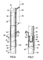
- Fig. 6 shows a section through the rear corner shown in Fig. 5 of the seating.
- the end 40 of the leg 22 is inserted into the plug element 16, the end of which is reduced in diameter and has a collar 42.
- the end 40 is preferably hydraulically compressed before the connection, so that it - after insertion into the element 16 can again experience a certain extent, so that it can be firmly attached to the inner wall of the plug element 16.
- the lower end 44 of the plug element 14 has a reduced outer diameter, so that the sleeve 30 is approximately flush with the remaining outer surface after being plugged onto the plug element 16.
- the side element 12 is integrally formed.
- the upper end 46 of the plug element 16 has a larger inner diameter in order to accommodate the lower end 48 of the plug element 26.
- the element 26 is formed at the lower end with diametrically opposite recesses 50 which cooperate with corresponding complementary recesses or ribs on the upper side of the plug element 16 in order to ensure that the plug element 16 is prevented from rotating.
- the lower end 48 of the plug element 26 is formed with a reduced outer diameter.
- the reinforcing sleeve 34 is arranged in this area. End 52 of armrest 24, which is of reduced diameter, is inserted from above.
- the outer and inner sides of the plug elements are slightly conical.
- a receptacle 54 is formed for fastening the backrest 28.
- This receptacle 54 is preferably designed in the form of a chamber into which a pin 56 formed on the backrest 28 is inserted.
- Fig. 7 show a section through a plug element 18 which is guided according to the section VI-VI through a front corner of the seating. It can be seen that the plug element 18 is formed at the lower end 60 with a reduced outer diameter. One end 62 of leg 20 is inserted into plug element 18 from below. This end 62 is preferred prior to insertion been hydraulically compressed. The plug-in element 18 sits with its lower end face on a collar 64 on the leg 20 of the seating furniture. In order to prevent the plug element 18 from bending out and being damaged, the reinforcement sleeve 32 is plugged onto the plug element 18, specifically in the region 60 which has a reduced outer diameter.
- the end 62 of the leg 20 is formed at the top with a blind hole 66, in which engages a pin 68 provided with a corresponding diameter, which is formed on the spar of the armrest 24. If no armrest 24 is arranged, a plug is inserted into the plug element 26 inserted, the top of which is approximately the same as that shown by the dashed line 70 in FIG. 6 corresponds, and in the plug element 18 a plug, the surface of which would have a course which corresponds to the line 72 in FIG. 7.
- the plug element 18 is preferably formed on the upper side with a collar 74, on which a collar 76 on the armrest 24 is preferably seated.
- the reinforcing sleeves 30, 32 and 34 are preferably made of a metal or a higher quality plastic with or without glass fiber reinforcement. For optical reasons, the reinforcing sleeves can have a different color than the plug elements.
- the angle of inclination ⁇ of the top of the plug element 26 is preferably 30 °. This angle of inclination ⁇ C of 30 ° is also realized on the reinforcing sleeves 30, 32 and 34 and the corresponding areas of reduced diameter of the plug elements 16 and 18.
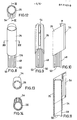
- FIG. 11 shows a cross section through the plug element 26, which essentially corresponds to the illustration according to FIG. 6.
- Fig. 12 shows a top view of the upper forehead area of the element 26 and
- Fig. 13 is a plan view of the lower end face.
- 14 shows a section through the plug element 26, from which the design of the receptacle 54 for fastening the backrest can be seen.
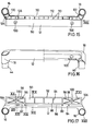
- FIG. 17 shows a plan view of the side element 12.
- the plug elements 16 and 18 are formed integrally with the side element 12.
- the side element 12 has an inclined edge surface 80, which is adjoined by a hollow chamber 85 provided with two openings 82 and 84.
- a vertical wall 88 connects to which a connecting at a winding ⁇ of about 30 0 extending bottom surface 90 to which, in turn, a vertical surface 92 is formed, which runs parallel to the surface 88th A surface is created by the surfaces 88, 90 and 92, which is reinforced by stiffening ribs 94.
- trough 98 through-openings 100 are formed in compartments provided with ribs 96, which are used for fastening coupling elements when the seating furniture is part of a row of seats.
- the channel 102 formed by the surfaces 98, 90 and 92 is closed off at the ends of end faces 104 and 106.
- 16 shows a side view of the side element 12, from which the outer wall 110 is partially cut away.
- 15 shows a view of the underside of the side element 10, from which in particular the bottom wall 19 of the channel 102 and a channel 112 formed by the walls 110, 84 and 88 are visible.
- the channel 112 is reinforced by transverse reinforcing ribs 113.
- FIG. 18 shows a view of the end face of a side element 12, on which the plug element 18 is integrally formed. From Fig. 18 it can be seen that the end face 106 is provided with a through opening 114 which serves to fasten the support surface for the seat surface.
- FIG. 20 shows a section through the side element 12 in the area in which the through opening 100 is designed for coupling to an adjacent piece of seating furniture.
- the bottom surface 90 is provided with a recess 116, which forms an approximately horizontal collar for receiving, for example, a screw which can be screwed into an internal thread 118 formed in the through opening 100.
- the through opening 100 can also serve to fasten the seat.
- the openings 82 and 84, which are arranged in the groove 86, can then be used for coupling adjacent seating furniture.
- a section through this opening is shown in FIG. 21.
- FIG. 22 shows a section through the front plug element 18, which corresponds to the section shown in FIG. 7.
- the plug elements 16, 18 and 26 are formed on the section 44, 48 and 60 of reduced diameter, on which the reinforcing sleeves 30, 32, 34 are arranged, on the outside with a longitudinal corrugation 120, 122 and 124, respectively.
- the reinforcing sleeves 30, 32, 36 can be designed with a longitudinal corrugation on their inside.
- covers 120, 122 arranged on the side part 12 in the foot region covers 120, 122 arranged on the side part 12 in the foot region.
- the covers 120, 122 are covered with the side element 12 in the region of the edge.
- the chamber formed by the cover and the side element can be foamed through an opening 124. This prevents the cover from moving in parallel.
- the cover with the side part is covered with a sonotrode.
- the rear part of the covers 120, 122 has lifts which provide stack supports for stacked seating furniture.
Landscapes
- Chair Legs, Seat Parts, And Backrests (AREA)
- Furniture Connections (AREA)
Applications Claiming Priority (2)
| Application Number | Priority Date | Filing Date | Title |
|---|---|---|---|
| DE19843427130 DE3427130A1 (de) | 1984-07-23 | 1984-07-23 | Sitzmoebel |
| DE3427130 | 1984-07-23 |
Publications (1)
| Publication Number | Publication Date |
|---|---|
| EP0171510A1 true EP0171510A1 (de) | 1986-02-19 |
Family
ID=6241353
Family Applications (1)
| Application Number | Title | Priority Date | Filing Date |
|---|---|---|---|
| EP85104876A Withdrawn EP0171510A1 (de) | 1984-07-23 | 1985-04-22 | Sitzmöbel |
Country Status (2)
| Country | Link |
|---|---|
| EP (1) | EP0171510A1 (enExample) |
| DE (1) | DE3427130A1 (enExample) |
Cited By (2)
| Publication number | Priority date | Publication date | Assignee | Title |
|---|---|---|---|---|
| GB2346322A (en) * | 1999-02-04 | 2000-08-09 | Arena Stadia Seating Ltd | Backrest mounting for a stadium seat |
| WO2007125277A3 (en) * | 2006-04-21 | 2007-12-27 | Gordon Ellis & Co | Seating arrangement |
Citations (2)
| Publication number | Priority date | Publication date | Assignee | Title |
|---|---|---|---|---|
| GB940583A (en) * | 1961-04-19 | 1963-10-30 | Dare Inglis Products Ltd | Chair assembly |
| GB1367196A (en) * | 1971-09-15 | 1974-09-18 | Albaplast Spa | Prestamped seating device |
-
1984
- 1984-07-23 DE DE19843427130 patent/DE3427130A1/de active Granted
-
1985
- 1985-04-22 EP EP85104876A patent/EP0171510A1/de not_active Withdrawn
Patent Citations (2)
| Publication number | Priority date | Publication date | Assignee | Title |
|---|---|---|---|---|
| GB940583A (en) * | 1961-04-19 | 1963-10-30 | Dare Inglis Products Ltd | Chair assembly |
| GB1367196A (en) * | 1971-09-15 | 1974-09-18 | Albaplast Spa | Prestamped seating device |
Cited By (3)
| Publication number | Priority date | Publication date | Assignee | Title |
|---|---|---|---|---|
| GB2346322A (en) * | 1999-02-04 | 2000-08-09 | Arena Stadia Seating Ltd | Backrest mounting for a stadium seat |
| GB2346322B (en) * | 1999-02-04 | 2002-10-09 | Arena Stadia Seating Ltd | Stadium etc seating |
| WO2007125277A3 (en) * | 2006-04-21 | 2007-12-27 | Gordon Ellis & Co | Seating arrangement |
Also Published As
| Publication number | Publication date |
|---|---|
| DE3427130A1 (de) | 1986-01-23 |
| DE3427130C2 (enExample) | 1988-06-30 |
Similar Documents
| Publication | Publication Date | Title |
|---|---|---|
| EP0649618B1 (de) | Sitzmöbel | |
| EP0824880B1 (de) | Stapelbarer Reihenstuhl für eine Saalbestuhlung oder dergleichen | |
| WO2012160013A1 (de) | Sitzschale für sitzmöbel | |
| EP0910264A1 (de) | Rahmen für liege- oder sitzmöbel | |
| EP0263442B1 (de) | Stuhl | |
| DE8709523U1 (de) | Polsterträger für einen Fahrzeugsitz | |
| DE3427130C2 (enExample) | ||
| DE9102301U1 (de) | Stuhl, insbesondere Bürostuhl | |
| DE8434844U1 (de) | Klappstuhl | |
| EP0479046B1 (de) | Stabelbares Sitzmöbel | |
| DE3130885A1 (de) | Aus stahlrohr aufgebautes sitzmoebel | |
| DE2519914C3 (de) | Sitzmöbel aus thermoplastischem Kunststoff | |
| DE3040868C2 (de) | Schublade | |
| DE29511707U1 (de) | Armlehnstuhl mit variierbaren Sitz- und Rückenlehnflächen | |
| DE202007007718U1 (de) | Schaukelstuhl | |
| DE19537123A1 (de) | Fußstütze mit verstellbarer Trittplatte | |
| DE2421896A1 (de) | Sitzmoebel, insbesondere stuhl, sessel, hocker o.dgl. | |
| DE9316227U1 (de) | Klappsessel | |
| DE20006788U1 (de) | Lösbare Holz-Eckverbindung für Mobilteile | |
| CH363137A (de) | Vorrichtung zur Verbindung von Gestellteilen bei einem Sitzmöbel | |
| CH682794A5 (de) | Stapelbares Sitzmöbel. | |
| DE8907591U1 (de) | Polstermöbel aus mehreren aneinanderstellbaren einzelnen Polstermöbelelementen | |
| DE3224814A1 (de) | Stuhlarmlehne mit schwenkbarer armauflage | |
| DE29600472U1 (de) | Rückenlehne | |
| DE9416762U1 (de) | Sitzmöbel |
Legal Events
| Date | Code | Title | Description |
|---|---|---|---|
| PUAI | Public reference made under article 153(3) epc to a published international application that has entered the european phase |
Free format text: ORIGINAL CODE: 0009012 |
|
| AK | Designated contracting states |
Designated state(s): AT BE CH DE FR GB IT LI LU NL SE |
|
| 17P | Request for examination filed |
Effective date: 19860305 |
|
| 17Q | First examination report despatched |
Effective date: 19870702 |
|
| STAA | Information on the status of an ep patent application or granted ep patent |
Free format text: STATUS: THE APPLICATION IS DEEMED TO BE WITHDRAWN |
|
| 18D | Application deemed to be withdrawn |
Effective date: 19881103 |
|
| RIN1 | Information on inventor provided before grant (corrected) |
Inventor name: LANGE, GERD |