EP0170499B1 - Procédé pour la fabrication d'une pièce structurale de renforcement - Google Patents
Procédé pour la fabrication d'une pièce structurale de renforcement Download PDFInfo
- Publication number
- EP0170499B1 EP0170499B1 EP85305294A EP85305294A EP0170499B1 EP 0170499 B1 EP0170499 B1 EP 0170499B1 EP 85305294 A EP85305294 A EP 85305294A EP 85305294 A EP85305294 A EP 85305294A EP 0170499 B1 EP0170499 B1 EP 0170499B1
- Authority
- EP
- European Patent Office
- Prior art keywords
- fibre body
- drawn
- tape
- fibre
- coiled
- Prior art date
- Legal status (The legal status is an assumption and is not a legal conclusion. Google has not performed a legal analysis and makes no representation as to the accuracy of the status listed.)
- Expired - Lifetime
Links
Images


Classifications
-
- B—PERFORMING OPERATIONS; TRANSPORTING
- B29—WORKING OF PLASTICS; WORKING OF SUBSTANCES IN A PLASTIC STATE IN GENERAL
- B29D—PRODUCING PARTICULAR ARTICLES FROM PLASTICS OR FROM SUBSTANCES IN A PLASTIC STATE
- B29D99/00—Subject matter not provided for in other groups of this subclass
- B29D99/0003—Producing profiled members, e.g. beams
-
- B—PERFORMING OPERATIONS; TRANSPORTING
- B29—WORKING OF PLASTICS; WORKING OF SUBSTANCES IN A PLASTIC STATE IN GENERAL
- B29C—SHAPING OR JOINING OF PLASTICS; SHAPING OF MATERIAL IN A PLASTIC STATE, NOT OTHERWISE PROVIDED FOR; AFTER-TREATMENT OF THE SHAPED PRODUCTS, e.g. REPAIRING
- B29C53/00—Shaping by bending, folding, twisting, straightening or flattening; Apparatus therefor
- B29C53/56—Winding and joining, e.g. winding spirally
-
- B—PERFORMING OPERATIONS; TRANSPORTING
- B29—WORKING OF PLASTICS; WORKING OF SUBSTANCES IN A PLASTIC STATE IN GENERAL
- B29C—SHAPING OR JOINING OF PLASTICS; SHAPING OF MATERIAL IN A PLASTIC STATE, NOT OTHERWISE PROVIDED FOR; AFTER-TREATMENT OF THE SHAPED PRODUCTS, e.g. REPAIRING
- B29C70/00—Shaping composites, i.e. plastics material comprising reinforcements, fillers or preformed parts, e.g. inserts
- B29C70/04—Shaping composites, i.e. plastics material comprising reinforcements, fillers or preformed parts, e.g. inserts comprising reinforcements only, e.g. self-reinforcing plastics
- B29C70/06—Fibrous reinforcements only
- B29C70/10—Fibrous reinforcements only characterised by the structure of fibrous reinforcements, e.g. hollow fibres
- B29C70/16—Fibrous reinforcements only characterised by the structure of fibrous reinforcements, e.g. hollow fibres using fibres of substantial or continuous length
- B29C70/20—Fibrous reinforcements only characterised by the structure of fibrous reinforcements, e.g. hollow fibres using fibres of substantial or continuous length oriented in a single direction, e.g. roofing or other parallel fibres
-
- B—PERFORMING OPERATIONS; TRANSPORTING
- B29—WORKING OF PLASTICS; WORKING OF SUBSTANCES IN A PLASTIC STATE IN GENERAL
- B29C—SHAPING OR JOINING OF PLASTICS; SHAPING OF MATERIAL IN A PLASTIC STATE, NOT OTHERWISE PROVIDED FOR; AFTER-TREATMENT OF THE SHAPED PRODUCTS, e.g. REPAIRING
- B29C70/00—Shaping composites, i.e. plastics material comprising reinforcements, fillers or preformed parts, e.g. inserts
- B29C70/04—Shaping composites, i.e. plastics material comprising reinforcements, fillers or preformed parts, e.g. inserts comprising reinforcements only, e.g. self-reinforcing plastics
- B29C70/28—Shaping operations therefor
- B29C70/40—Shaping or impregnating by compression not applied
- B29C70/50—Shaping or impregnating by compression not applied for producing articles of indefinite length, e.g. prepregs, sheet moulding compounds [SMC] or cross moulding compounds [XMC]
-
- B—PERFORMING OPERATIONS; TRANSPORTING
- B29—WORKING OF PLASTICS; WORKING OF SUBSTANCES IN A PLASTIC STATE IN GENERAL
- B29C—SHAPING OR JOINING OF PLASTICS; SHAPING OF MATERIAL IN A PLASTIC STATE, NOT OTHERWISE PROVIDED FOR; AFTER-TREATMENT OF THE SHAPED PRODUCTS, e.g. REPAIRING
- B29C70/00—Shaping composites, i.e. plastics material comprising reinforcements, fillers or preformed parts, e.g. inserts
- B29C70/04—Shaping composites, i.e. plastics material comprising reinforcements, fillers or preformed parts, e.g. inserts comprising reinforcements only, e.g. self-reinforcing plastics
- B29C70/28—Shaping operations therefor
- B29C70/54—Component parts, details or accessories; Auxiliary operations, e.g. feeding or storage of prepregs or SMC after impregnation or during ageing
- B29C70/542—Placing or positioning the reinforcement in a covering or packaging element before or during moulding, e.g. drawing in a sleeve
-
- E—FIXED CONSTRUCTIONS
- E04—BUILDING
- E04C—STRUCTURAL ELEMENTS; BUILDING MATERIALS
- E04C5/00—Reinforcing elements, e.g. for concrete; Auxiliary elements therefor
- E04C5/07—Reinforcing elements of material other than metal, e.g. of glass, of plastics, or not exclusively made of metal
-
- B—PERFORMING OPERATIONS; TRANSPORTING
- B29—WORKING OF PLASTICS; WORKING OF SUBSTANCES IN A PLASTIC STATE IN GENERAL
- B29C—SHAPING OR JOINING OF PLASTICS; SHAPING OF MATERIAL IN A PLASTIC STATE, NOT OTHERWISE PROVIDED FOR; AFTER-TREATMENT OF THE SHAPED PRODUCTS, e.g. REPAIRING
- B29C35/00—Heating, cooling or curing, e.g. crosslinking or vulcanising; Apparatus therefor
- B29C35/02—Heating or curing, e.g. crosslinking or vulcanizing during moulding, e.g. in a mould
-
- B—PERFORMING OPERATIONS; TRANSPORTING
- B29—WORKING OF PLASTICS; WORKING OF SUBSTANCES IN A PLASTIC STATE IN GENERAL
- B29L—INDEXING SCHEME ASSOCIATED WITH SUBCLASS B29C, RELATING TO PARTICULAR ARTICLES
- B29L2031/00—Other particular articles
- B29L2031/06—Rods, e.g. connecting rods, rails, stakes
Definitions
- This invention relates to a process for manufacturing a structural reinforcing member which is made of glass fibre, reinforced plastic, carbon fibre reinforced plastic or the like, whose precise sectional shape is not severely restricted by its manner of manufacture and which is used, for instance, as a main reinforcing bar for concrete, a reinforcing bar for shear resistance or the like.
- a process for manufacturing a structural reinforcing member of this kind wherein a fibre body comprising a number of threads made of reinforcing fibre is impregnated with a hardenable material such as a thermosetting resin or the like, and is then introduced into a drawing die so as to be formed into a drawn body having a predetermine sectional shape, and the drawn fibre body is subjected to a hardening treatment in a metallic hardening mould.
- a hardenable material such as a thermosetting resin or the like
- the purpose of this invention is to remove the foregoing inconveniences and provide a process for manufacturing a structural reinforcing member having grooves of different form, and which does not require the conventional metallic hardening mould and is improved in productivity.
- a process for manufacturing a structural reinforcing member wherein a fibre body comprising a plurality of threads of reinforcing fibre is impregnated with a hardenable material and is introduced into a drawing die having a desired sectional shape so as to be formed into a drawn fibre body having a predetermined sectional shape, whereupon a tape is coiled therearound so as to cover the same and the drawn fibre body is subjected to a hardening treatment, characterised in that a string member is coiled around the drawn fibre body covered with the coiled tape so that the coiled string member may penetrate the drawn fibre body and thereafter the drawn fibre body is subjected to said hardening treatment.
- the present invention also provides a process for manufacturing a structural reinforcing member wherein a fibre body comprising a plurality of threads of reinforcing fibre is impregnated with a hardenable material and is introduced into a drawing die having a desired sectional shape so as to be formed into a drawn fibre body having a predetermined sectional shape, whereupon a tape is coiled therearound so as to cover the same and the drawn fibre body is subjected to a hardening treatment, characterised in that, before the tape is coiled around the drawn fibre body, a shaping member is provided on the periphery of the drawn fibre body, the tape is coiled around the drawn fibre body and the shaping member so as to cover the same, the shaping member is forced to penetrate the drawn fibre body, and thereafter the drawn fibre body is subjected to said hardening treatment.
- Figures 1 and 2 show one embodiment of a process for manufacturing of a structural reinforcing member of this invention.
- Numeral 1 denotes a fibre body.
- Numeral 2 denotes a supply source of a thread 3.
- the thread 3 comprises roving, for instance, and is made of any kind of fibre selected from, for example, any inorganic fibre such as carbon fibre, glass fibre, ceramic fibre, etc., any heat resisting organic fibre such as aromatic polyamide, aromatic polyether amide, aromatic polysulphonamide, aromatic polyketone amide, aromatic polyamine amide, etc., and any stainless metallic fibre.
- the thread need not be a yarn selected from, for example, roving, multifilaments, strands and slivers, but may be a monofilament.
- the thread comprises roving as mentioned above, and these threads 3 are collected into a parallel arrangement, with or without twist, to form a fibre body 1, and the fibre body 1 is impregnated with a hardenable material 4 contained in a soaking container.
- the hardenable material may be any cold or heat setting resin such as of epoxy type, vinyl ester type, phenolic type, polyimide, etc., any cold or heat setting inorganic material such as of alkali metallic silicate type, colloidal silica type, phosphate type, cement type, etc., or a mixture of the foregoing organic and inorganic cold or heat setting materials.
- any cold or heat setting resin such as of epoxy type, vinyl ester type, phenolic type, polyimide, etc.
- any cold or heat setting inorganic material such as of alkali metallic silicate type, colloidal silica type, phosphate type, cement type, etc., or a mixture of the foregoing organic and inorganic cold or heat setting materials.
- the hardenable material there may be present a hardening agent, a colouring agent, or other agents as occasion demands.
- the fibre body 1, after being impregnated with the hardenable material 4 is introduced into a drawing die 5 having a desired sectional shape such as a circle or the like so as to be formed into a drawn body having a predetermined sectional shape according to the die.
- numeral 6 denotes a drawing means for drawing the fibre body 1 from the die 5.
- a tape 7 is coiled around the fibre body 1 drawn from the die 5 by wrapping apparatus (not shown), for instance, so as to cover the same, and thereafter the drawn fibre body 1 covered with the coiled tape 7 is moved into a heating chamber 8 in the case where a thermosetting resin is used as the hardenable material 4 in order to subject the material 4 to a hardening treatment.
- a thermosetting resin is used as the hardenable material 4 in order to subject the material 4 to a hardening treatment.
- the drawn fibre body 1 becomes completely rigid, it is taken out from the heating chamber 8, and is then cut by a cutter 9 into pieces of a predetermined length.
- the tape is removed from each length to obtain a large number of structural reinforcing members.
- the hardening treatment may be divided into two stages.
- an additional heating chamber (not shown) is provided before or after the heating chamber 8.
- the heating chamber 8 is not necessary, and, as shown in Figure 3, the drawn fibre body 1 is cut by the cutter 9 to a predetermined length, without being heated, and thereafter a large number of cut fibre bodies are allowed to stand until hardened completely at room temperature to produce structural reinforcing members.
- the tape 7 there may be used paper tape, metallic tape or resin tape.
- the tape 7 is preferably coated with a releasing agent 10 such as silicone resin or the like so that it may be easily removed after the hardening treatment of the drawn fibre body 1.
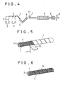
- the tape 7 is coiled, by a wrapping apparatus (not shown), around the fibre body 1 impregnated with a thermosetting resin 4 and drawn from the die 5 in the similar manner as in the foregoing embodiment, and thereafter an elongate flexible member 11 (e.g. a string member 11) is coiled, at predetermined intervals, around the coiled tape 7 which has been disposed around the fibre body 1 by a winding apparatus or the like (not shown) so as to eat into or penetrate the periphery of the fibre body 1.
- the fibre body 1 is moved into the heating chamber 8 and is subjected to a complete hardening or curing treatment within the chamber 8.
- the complete rigid fibre body 1 taken out from the chamber 8 is cut by the cutter 9 into pieces of a desired length and the resultant cut tape 7 is removed along with the cut member 11 from each of the resultant cut fibre bodies 1 to obtain a large number of deformed structural reinforcing members each having a coiled groove 14 in the periphery of the rigid fibre body 1, as shown in Figure 6.
- the tape 7 is coiled around the fibre body 1 continuously drawn from the die 5 and, if necessary, in addition the member 11 is coiled around the fibre body wrapped in the tape 7.
- the tape 7 and, if necessary, the member 11 may be disposed around a fibre body of a predetermined length prepared by cutting the fibre body 1. Furthermore, the tape 7 or the cut tape removed from the fibre body can be used again.
- the elongate member 11 may be made of paper, metal or synthetic resin, and the sectional shape thereof, the coiled pitch thereof or the manner of coiling thereof may be changed as desired, so that various deformed structural reinforcing members can be easily produced.
- the fibre body 1 impregnated with a cold setting resin is introduced into the die 5 having a desired sectional shape, for instance, a circular shape, and is drawn into a predetermined sectional shaped body. It is then cut by the cutter 9 into pieces of a predetermined length to obtain a large number of fibre bodies 1, as shown in Figure 7.
- a pair of shaping members 12 coated with a releasing agent and each comprising a rod whose sectional shape is a circle are disposed on the right and left side of the fibre body 1 and along the entire length of the fibre body 1, as shown in Figure 8.
- the tape 7 is coiled around the fibre body 1 so as to fasten the shaping members 12 to the fibre body 1 and thrust them into the same so that the circular sectional shape of the fibre, body 1 is deformed.
- the fibre body 1 is allowed to stand at room temperature until it is completely hardened, as shown in Figure 9.
- the deformed sectional shape of the fibre body 1 is attained by fastening the shaping members 12 to the fibre body with the tape 7 so as to thrust them into the fibre body 1.
- the shape may be attained by pushing the members 12 into the drawn fibre body 1 by means of a pressing apparatus before the tape 7 is coiled therearound, and thus in this case, the tape 7 serves to keep the members 12 in their thrust condition.
- the shaping member 12 may be made of metal, ceramic, inorganic or organic material or a combination thereof.
- the shape of the shaping member 12 in the longitudinal direction may be of any desired shape other than the straight shape used in the above embodiment.
- the longitudinal shape thereof may be a curved shape such as a waveform shape, in which case a deformed structural reinforcing member having a waveform groove 14 extending in the longitudinal direction thereof is produced as shown in Figure 11.
- the shaping member 12 is not limited to one of bar shape, but may be of spherical shape, of star shape or of any other desired shape. A large number of these may be distributed on the periphery of the fibre body 1, over the entire length thereof.
- the shaping member 12 may be a pliable long member and in this case the pliable shaping member is coiled around the fibre body 1 so as to deform the same.
- a deformed sectional shape is given thereto by the shaping member 12.
- a deformed sectional shape may be given thereto by the shaping member 12, and thereafter the drawn fibre body 1 with the shaping member 12 set therein is cut to a predetermined length.
- thermosetting resin which comprises 100 parts of bisphenol A type epoxy resin, 33 parts of diaminobiphenyl sulphone, 1 part of boron trif- luoromonoethylamine and 100 parts of methy- letherketone so that the fibre body was impregnated with the thermosetting resin in a ratio of the resin to the fibre body of 80:100.
- parts means “parts by weight”.
- PET (polyethyleneterephthate) tape 7mm in width and 50 microns in thickness was coiled around the fibre body so as to cover the same, and the body was passed through a heating chamber at 130°C for 2 minutes so that the body is subjected to a hardening treatment.
- the resultant semi-rigid fibre body taken out from the chamber was cut into pieces of 30 m in length and the cut fibre bodies were introduced into a heating chamber and were heated at 130°C for 10 minutes and thereafter at 170°C for 2 hours.
- the bodies were taken out therefrom, the tape was removed from each of the fibre bodies, each fibre body was cut into pieces of 1.5 m in length, and thus there were produced a large number of structural reinforcing members.
- a fibre body obtained in almost the same manner as in Example 1 was impregnated with a cold setting resin which comprises 100 parts of bisphenol type epoxy resin, and 10 parts of aliphatic amine in a mixing ratio of the resin to the fibre body of 80:100.
- the body was introduced into a die of a circular sectional shape, and was drawn therefrom to form a drawn fibre body of a circular sectional shape of about 3 mm in diameter.
- a polypropylene tape 7 mm in width and 70 microns in thickness was coiled around the drawn fibre body so as to cover the same, and the body was cut into pieces 1.5 m long in sequence.
- the large number of fibre bodies of a predetermined length were allowed to stand for 4 days until they were completely hardened, and thereafter the cut tape was removed from each fibre body, and thus there were obtained a large number of structural reinforcing members.
- a string member comprising PET monofilament of 3000 denier was coiled, at a coiled pitch of 7 mm, around on the drawn fibre body covered with the coiled tape in the same manner as in Example 1, so as to penetrate into the fibre body, and thereafter the fibre body bearing the coiled tape and the coiled string member was treated in the same manner as in Example 1.
Claims (6)
Priority Applications (1)
| Application Number | Priority Date | Filing Date | Title |
|---|---|---|---|
| MYPI87001930A MY100604A (en) | 1984-07-27 | 1987-09-25 | Structural reinforcing member |
Applications Claiming Priority (8)
| Application Number | Priority Date | Filing Date | Title |
|---|---|---|---|
| JP155491/84 | 1984-07-27 | ||
| JP15549084A JPS6135231A (ja) | 1984-07-27 | 1984-07-27 | 構造用異形補強材の製造法 |
| JP15548984A JPS6135230A (ja) | 1984-07-27 | 1984-07-27 | 構造用補強材の連続製造法 |
| JP15549184A JPS6135232A (ja) | 1984-07-27 | 1984-07-27 | 構造用異形補強材の製造法 |
| JP155489/84 | 1984-07-27 | ||
| JP155490/84 | 1984-07-27 | ||
| JP59170024A JPS6149809A (ja) | 1984-08-16 | 1984-08-16 | 構造用異形補強材の製造法 |
| JP170024/84 | 1984-08-16 |
Publications (3)
| Publication Number | Publication Date |
|---|---|
| EP0170499A2 EP0170499A2 (fr) | 1986-02-05 |
| EP0170499A3 EP0170499A3 (en) | 1987-07-29 |
| EP0170499B1 true EP0170499B1 (fr) | 1990-09-19 |
Family
ID=27473355
Family Applications (1)
| Application Number | Title | Priority Date | Filing Date |
|---|---|---|---|
| EP85305294A Expired - Lifetime EP0170499B1 (fr) | 1984-07-27 | 1985-07-25 | Procédé pour la fabrication d'une pièce structurale de renforcement |
Country Status (4)
| Country | Link |
|---|---|
| US (1) | US4770832A (fr) |
| EP (1) | EP0170499B1 (fr) |
| DE (1) | DE3579770D1 (fr) |
| MY (1) | MY100604A (fr) |
Families Citing this family (17)
| Publication number | Priority date | Publication date | Assignee | Title |
|---|---|---|---|---|
| ATE65818T1 (de) * | 1985-11-07 | 1991-08-15 | Akzo Nv | Bewehrungselement aus kunststoff, verwendbar in armiertem beton, insbesondere in vorgespanntem beton, armierter beton versehen mit solchen bewehrungselementen und verfahren zur herstellung von bewehrungselementen und armiertem und vorgespanntem beton. |
| US5230906A (en) * | 1986-11-24 | 1993-07-27 | Polytex Plastic Sa | Method of and apparatus for manufacturing fiber-reinforced plastics articles |
| SE457691B (sv) * | 1987-05-22 | 1989-01-23 | Nobel Plast Ab | Metod foer framstaellning av protetiska konstruktioner av kompositmaterial med betydande fiberinnehaall |
| JPH06143478A (ja) * | 1992-11-06 | 1994-05-24 | Nippon Steel Corp | 繊維強化プラスチック製筋材とその製造方法 |
| US5749211A (en) * | 1992-11-06 | 1998-05-12 | Nippon Steel Corporation | Fiber-reinforced plastic bar and production method thereof |
| JP2756069B2 (ja) * | 1992-11-27 | 1998-05-25 | 株式会社ペトカ | コンクリート補強用炭素繊維 |
| US5993713A (en) * | 1992-12-01 | 1999-11-30 | De La Puerta; Enrique | Reinforced composite shapes and method and apparatus for their manufacture |
| JP2613844B2 (ja) * | 1993-12-03 | 1997-05-28 | 小松化成株式会社 | 繊維強化プラスチック製ロッドの連続引抜成形方法及びその装置 |
| DE4421650A1 (de) | 1994-06-21 | 1996-01-04 | Hoechst Ag | Formkörper enthaltend Garne oder Bänder aus Fasern aus aromatischen Polyamiden, Garne oder Bänder aus aromatischen Polyamiden, sowie Verwendung dieser Garne zur Verstärkung von Polymerbeton oder von hydraulisch oder an der Luft abbindenden Materialien |
| DE19512521A1 (de) * | 1995-04-04 | 1996-10-10 | Coia Gmbh | Verfahren für die kontinuierliche Herstellung von verstärkten nichtmetallischen Stützelementen |
| KR100485080B1 (ko) * | 2002-06-25 | 2005-04-28 | 주식회사 한국화이바 | 유리섬유 강화 플라스틱 환봉의 제조방법 |
| DE102011015160A1 (de) * | 2011-03-26 | 2012-09-27 | Daimler Ag | Faserverbundkunststoffteil und Herstellungsverfahren |
| DE102014102861A1 (de) * | 2014-03-04 | 2015-09-10 | Technische Universität Dresden | Bewehrungsgitter für den Betonbau, Hochleistungsfilamentgarn für den Betonbau und Verfahren zu deren Herstellung |
| DE102015100386A1 (de) * | 2015-01-13 | 2016-07-14 | Technische Universität Dresden | Bewehrungsstab aus Filamentverbund und Verfahren zu dessen Herstellung |
| ITVI20150072A1 (it) | 2015-03-16 | 2016-09-16 | Carbonveneta Tecnologia Nei Compositi S R L | Procedimento per la realizzazione di un connettore del tipo cosiddetto a "fiocco" |
| EP3091135A1 (fr) * | 2015-05-04 | 2016-11-09 | Evonik Degussa GmbH | Barre d'armature, procédé de fabrication et utilisation |
| JP7055314B1 (ja) | 2020-12-28 | 2022-04-18 | 中川産業株式会社 | 筋金棒体の製造方法およびこれに使用する浸漬器 |
Family Cites Families (20)
| Publication number | Priority date | Publication date | Assignee | Title |
|---|---|---|---|---|
| CA705294A (en) * | 1965-03-09 | R. Boggs Leroy | Method and apparatus for forming fibre reinforced resin articles | |
| US1128480A (en) * | 1914-05-04 | 1915-02-16 | Charles E Miller | Process of making tires. |
| US2571717A (en) * | 1946-02-16 | 1951-10-16 | Libbey Owens Ford Glass Co | Shaft for fishing rods |
| US2694661A (en) * | 1952-02-12 | 1954-11-16 | Parallel Plastics Co | Process for forming adhesive-embedded fiber rods |
| US2749266A (en) * | 1953-05-21 | 1956-06-05 | Gen Tire & Rubber Co | Method of making reinforced glass fiber articles |
| US3244784A (en) * | 1960-01-15 | 1966-04-05 | Universal Moulded Fiber Glass | Method for forming fibre reinforced resin articles |
| JPS516071A (ja) * | 1974-07-02 | 1976-01-19 | Mitsubishi Electric Corp | Jitsukochihenkansochi |
| US3960473A (en) * | 1975-02-06 | 1976-06-01 | The Glastic Corporation | Die structure for forming a serrated rod |
| DE2756917A1 (de) * | 1976-12-22 | 1978-07-06 | Sea Log Corp | Verfahren zur herstellung von mit glasfasern verstaerkten harzgebilden |
| US4194873A (en) * | 1978-01-09 | 1980-03-25 | Ppg Industries, Inc. | Apparatus for making pultruded product |
| JPS54148087A (en) * | 1978-05-12 | 1979-11-19 | Central Glass Co Ltd | Article of glass fiber reinforced resin and its production |
| US4244765A (en) * | 1978-06-27 | 1981-01-13 | Tomotoshi Tokuno | Method for manufacturing a resin-reinforced carbon fiber product |
| GB1543586A (en) * | 1978-07-24 | 1979-04-04 | Whitworth B | Flexible tube |
| JPS5555828A (en) * | 1978-10-20 | 1980-04-24 | Central Glass Co Ltd | Forming method for rugged pattern on surface of glass fiber-reinforced resin material |
| JPS5561430A (en) * | 1978-10-31 | 1980-05-09 | Daiwa Seiko Inc | Manufacturing method for tubular object |
| DE3121241C2 (de) * | 1980-05-28 | 1984-07-19 | Dainippon Ink And Chemicals, Inc., Tokio/Tokyo | Verfahren zum Herstellen eines Verbundkunststoffrohres aus thermoplastischem Harz |
| SU937207A1 (ru) * | 1980-08-22 | 1982-06-23 | Институт Строительства И Архитектуры Госстроя Бсср | Способ изготовлени стеклопластиковой арматуры и устройство дл его осуществлени |
| FR2503021A1 (fr) * | 1981-04-06 | 1982-10-08 | Simon Jean Pierre | Procede de fabrication de tuteurs, installation pour la mise en oeuvre de ce procede et tuteurs obtenus |
| JPS58170963A (ja) * | 1982-03-31 | 1983-10-07 | Sumitomo Electric Ind Ltd | 繊維強化プラスチツク製歯車 |
| JPS60187534A (ja) * | 1984-03-07 | 1985-09-25 | Mitsui Constr Co Ltd | 構造用補強材の連続製造法 |
-
1985
- 1985-07-25 DE DE8585305294T patent/DE3579770D1/de not_active Expired - Fee Related
- 1985-07-25 US US06/758,721 patent/US4770832A/en not_active Expired - Fee Related
- 1985-07-25 EP EP85305294A patent/EP0170499B1/fr not_active Expired - Lifetime
-
1987
- 1987-09-25 MY MYPI87001930A patent/MY100604A/en unknown
Also Published As
| Publication number | Publication date |
|---|---|
| US4770832A (en) | 1988-09-13 |
| DE3579770D1 (de) | 1990-10-25 |
| EP0170499A2 (fr) | 1986-02-05 |
| EP0170499A3 (en) | 1987-07-29 |
| MY100604A (en) | 1990-12-15 |
Similar Documents
| Publication | Publication Date | Title |
|---|---|---|
| EP0170499B1 (fr) | Procédé pour la fabrication d'une pièce structurale de renforcement | |
| US4978360A (en) | Method of manufacturing a composite implant prosthesis | |
| US4992313A (en) | Fiber-reinforced plastic strut connecting link | |
| US4902297A (en) | Composite implant prosthesis | |
| US4414049A (en) | Method of manufacture of an energy absorbing beam | |
| DE3506037C1 (de) | Schraubenfeder sowie Verfahren zu deren Herstellung | |
| EP0177687B1 (fr) | Procédé pour la fabrication d'une structure plastique renforcée par des fibres | |
| JPH0617075B2 (ja) | 表面に凸条を有する繊維強化プラスチック製ロッド及びその製造方法 | |
| EP0172028B1 (fr) | Objet inorganique renforcé par des fibres | |
| US7513970B2 (en) | Method and apparatus for production of a reinforcement bar | |
| JPH0615078Y2 (ja) | コンクリ−ト用補強材 | |
| US3979493A (en) | Method for producing glass fiber reinforcing members | |
| JPS6135231A (ja) | 構造用異形補強材の製造法 | |
| JPS6149809A (ja) | 構造用異形補強材の製造法 | |
| JPS6135232A (ja) | 構造用異形補強材の製造法 | |
| EP1022112A2 (fr) | Dispositif pour l'enroulement de filaments enduits à haute température | |
| JPH01249326A (ja) | 繊維強化樹脂ばねの製造方法 | |
| EP3967483A1 (fr) | Système de moulage de corps moulé composite et procédé de production | |
| JPH0421447B2 (fr) | ||
| JP2653702B2 (ja) | コンクリート補強筋とその製造方法 | |
| DE3401195A1 (de) | Verbundwerkstoffe aus polyetherimid und verstaerkungsfasern | |
| JPH09226012A (ja) | Frp製コイルバネ用frp素線の製造方法 | |
| JPS645822A (en) | Manufacture of fiber reinforced formed material | |
| von Bonin et al. | Matrix Materials Process for Their Preparation and Their Use in the Preparation of Composite Materials | |
| JPH09267401A (ja) | Frp管およびその製造方法 |
Legal Events
| Date | Code | Title | Description |
|---|---|---|---|
| PUAI | Public reference made under article 153(3) epc to a published international application that has entered the european phase |
Free format text: ORIGINAL CODE: 0009012 |
|
| AK | Designated contracting states |
Designated state(s): CH DE FR GB LI NL |
|
| PUAL | Search report despatched |
Free format text: ORIGINAL CODE: 0009013 |
|
| AK | Designated contracting states |
Kind code of ref document: A3 Designated state(s): CH DE FR GB LI NL |
|
| 17P | Request for examination filed |
Effective date: 19871104 |
|
| 17Q | First examination report despatched |
Effective date: 19881028 |
|
| GRAA | (expected) grant |
Free format text: ORIGINAL CODE: 0009210 |
|
| NLV1 | Nl: lapsed or annulled due to failure to fulfill the requirements of art. 29p and 29m of the patents act | ||
| AK | Designated contracting states |
Kind code of ref document: B1 Designated state(s): CH DE FR GB LI NL |
|
| REF | Corresponds to: |
Ref document number: 3579770 Country of ref document: DE Date of ref document: 19901025 |
|
| ET | Fr: translation filed | ||
| PLBE | No opposition filed within time limit |
Free format text: ORIGINAL CODE: 0009261 |
|
| STAA | Information on the status of an ep patent application or granted ep patent |
Free format text: STATUS: NO OPPOSITION FILED WITHIN TIME LIMIT |
|
| 26N | No opposition filed | ||
| PGFP | Annual fee paid to national office [announced via postgrant information from national office to epo] |
Ref country code: GB Payment date: 19930515 Year of fee payment: 9 |
|
| PGFP | Annual fee paid to national office [announced via postgrant information from national office to epo] |
Ref country code: CH Payment date: 19930720 Year of fee payment: 9 |
|
| PGFP | Annual fee paid to national office [announced via postgrant information from national office to epo] |
Ref country code: FR Payment date: 19930723 Year of fee payment: 9 |
|
| PGFP | Annual fee paid to national office [announced via postgrant information from national office to epo] |
Ref country code: NL Payment date: 19930731 Year of fee payment: 9 |
|
| PGFP | Annual fee paid to national office [announced via postgrant information from national office to epo] |
Ref country code: DE Payment date: 19930929 Year of fee payment: 9 |
|
| PG25 | Lapsed in a contracting state [announced via postgrant information from national office to epo] |
Ref country code: GB Effective date: 19940725 |
|
| PG25 | Lapsed in a contracting state [announced via postgrant information from national office to epo] |
Ref country code: LI Effective date: 19940731 Ref country code: CH Effective date: 19940731 |
|
| PG25 | Lapsed in a contracting state [announced via postgrant information from national office to epo] |
Ref country code: NL Effective date: 19950201 |
|
| NLV4 | Nl: lapsed or anulled due to non-payment of the annual fee | ||
| GBPC | Gb: european patent ceased through non-payment of renewal fee |
Effective date: 19940725 |
|
| PG25 | Lapsed in a contracting state [announced via postgrant information from national office to epo] |
Ref country code: FR Effective date: 19950331 |
|
| REG | Reference to a national code |
Ref country code: CH Ref legal event code: PL |
|
| PG25 | Lapsed in a contracting state [announced via postgrant information from national office to epo] |
Ref country code: DE Effective date: 19950401 |
|
| REG | Reference to a national code |
Ref country code: FR Ref legal event code: ST |