EP0169097B1 - Gleitführung mit Schraube mit manuellem, elektrischem oder sonstigem Antrieb - Google Patents
Gleitführung mit Schraube mit manuellem, elektrischem oder sonstigem Antrieb Download PDFInfo
- Publication number
- EP0169097B1 EP0169097B1 EP85401117A EP85401117A EP0169097B1 EP 0169097 B1 EP0169097 B1 EP 0169097B1 EP 85401117 A EP85401117 A EP 85401117A EP 85401117 A EP85401117 A EP 85401117A EP 0169097 B1 EP0169097 B1 EP 0169097B1
- Authority
- EP
- European Patent Office
- Prior art keywords
- seat
- screw
- down unit
- respect
- shaft
- Prior art date
- Legal status (The legal status is an assumption and is not a legal conclusion. Google has not performed a legal analysis and makes no representation as to the accuracy of the status listed.)
- Expired - Lifetime
Links
- 230000002441 reversible effect Effects 0.000 claims abstract description 6
- 238000006073 displacement reaction Methods 0.000 claims description 3
- 230000005540 biological transmission Effects 0.000 claims description 2
- 230000000903 blocking effect Effects 0.000 description 4
- 230000006378 damage Effects 0.000 description 2
- 230000002427 irreversible effect Effects 0.000 description 2
- 230000004048 modification Effects 0.000 description 2
- 238000012986 modification Methods 0.000 description 2
- 240000008042 Zea mays Species 0.000 description 1
- 230000006978 adaptation Effects 0.000 description 1
- 238000009434 installation Methods 0.000 description 1
- 239000011229 interlayer Substances 0.000 description 1
Images


Classifications
-
- B—PERFORMING OPERATIONS; TRANSPORTING
- B60—VEHICLES IN GENERAL
- B60N—SEATS SPECIALLY ADAPTED FOR VEHICLES; VEHICLE PASSENGER ACCOMMODATION NOT OTHERWISE PROVIDED FOR
- B60N2/00—Seats specially adapted for vehicles; Arrangement or mounting of seats in vehicles
- B60N2/02—Seats specially adapted for vehicles; Arrangement or mounting of seats in vehicles the seat or part thereof being movable, e.g. adjustable
- B60N2/0224—Non-manual adjustments, e.g. with electrical operation
- B60N2/02246—Electric motors therefor
-
- Y—GENERAL TAGGING OF NEW TECHNOLOGICAL DEVELOPMENTS; GENERAL TAGGING OF CROSS-SECTIONAL TECHNOLOGIES SPANNING OVER SEVERAL SECTIONS OF THE IPC; TECHNICAL SUBJECTS COVERED BY FORMER USPC CROSS-REFERENCE ART COLLECTIONS [XRACs] AND DIGESTS
- Y10—TECHNICAL SUBJECTS COVERED BY FORMER USPC
- Y10T—TECHNICAL SUBJECTS COVERED BY FORMER US CLASSIFICATION
- Y10T74/00—Machine element or mechanism
- Y10T74/19—Gearing
- Y10T74/19637—Gearing with brake means for gearing
-
- Y—GENERAL TAGGING OF NEW TECHNOLOGICAL DEVELOPMENTS; GENERAL TAGGING OF CROSS-SECTIONAL TECHNOLOGIES SPANNING OVER SEVERAL SECTIONS OF THE IPC; TECHNICAL SUBJECTS COVERED BY FORMER USPC CROSS-REFERENCE ART COLLECTIONS [XRACs] AND DIGESTS
- Y10—TECHNICAL SUBJECTS COVERED BY FORMER USPC
- Y10T—TECHNICAL SUBJECTS COVERED BY FORMER US CLASSIFICATION
- Y10T74/00—Machine element or mechanism
- Y10T74/19—Gearing
- Y10T74/19642—Directly cooperating gears
- Y10T74/19698—Spiral
- Y10T74/19819—Driven rack or shaft
Definitions
- the present invention relates to the production of two parallel slides for longitudinal adjustment in front or back for a vehicle seat.
- the design of each slide is made by two profiles, one fixed to the vehicle floor, the second fixed below the seat moving with it; a reversible pitch screw allows the displacement of the upper section relative to the lower when this screw is made free of its blocking.
- each slide is the small size of the screw arranged in place of a known design lock, and being able to block this screw in a chosen location.
- a retaining box is arranged under the screw as well as behind the notched part of the fixed profile for, in the case of significant forces on the slide assembly, driving the toothing to avoid detachment of the screw.
- a braking element acts on the screw to ensure the positioning of the movable upper part relative to the fixed lower part.
- This immobilization means can be controlled either by manual means (spreader) which acts by a cam on the two brake shoes, or by electromagnetic means (reverser) which by means of a rod mounted at the end of the cam loosens the jaws, either by a micromotor which acts as with an electromagnet.
- This set of slides can be equipped with a motor acting on the screw by means of a gear train. In this case, it is the motor which retains the assembly, no braking element being disposed on the screw.
- DE-A-3 143 122 discloses a seat for vehicles the seat of which can be adjusted in the vertical direction (front part of the seat) and in the longitudinal direction by means of a rack, or the like, placed on the slide rail; the movable rail, which can move relative to the fixed rail, carries an endless screw whose rotation is actuated by a drive motor group whose supply is controlled by a potentiometer.
- the worm gear is irreversible and can only move the seat when the drive motor is rotating.
- the drive device of the upper profile is always secured to the irreversible worm. This therefore does not allow precise longitudinal positioning of the seat and, moreover, there is no particular device for blocking each worm.
- the geared motor group is integral with the movable upper profile of the slide whose fixed lower profile carries on its inner face a toothing forming a rack, the geared group being separated from the upper profile by members facilitating the sliding of the two profiles relative to each other, endless screws mounted on a shaft that can rotate relative to the rack being connected to a transfer box secured to the gearmotor group, by a gear train and by angular gearboxes by means of a shaft for balancing the rotation of the worms mounted on each side of the seat in order to allow the two respective slides to work together to move the seat, the invention is characterized in that these worms are reversible and are locked in the po sition chosen from the seat by pads with inclined upper faces bearing on each screw considered and normally tightened one against the other by springs, the screws being released by the bars of a bar whose rotation is controlled manually or so motorized.
- the geared motor group and the transfer case are arranged, the first, transversely, and, the second, longitudinally with respect to the axis of the vehicle.
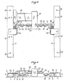
- the wing 1a is shaped to receive the devices 3 facilitating the sliding of the upper section 4 of the slide with respect to the lower section 1 which is fixed and normally secured to the floor of the vehicle.
- the vertical wing 4a of the upper profile 4 is cut over a certain length to allow the installation of a housing 5 which is held on the upper profile 4 by the cover 5a and, on either side of the housing 5, are arranged brackets 6, 7 intended to form on the side of the bracket 6, a bearing 8 in which rests a shaft 9 serving as a rotation shaft to a worm 10.
- 11 designates the locking key, on the shaft 9, the worm 10.
- the part 14 in L has a recess 14a which contains two pinions 17, 18 meshing with each other so that the half-shaft 15 rotates at the same time as the shaft 9 but in the opposite direction.
- the half-shaft 15 carries a return pinion 19 cooperating with a second return pinion 20 mounted at the end of a shaft 21 whose role will be explained below.
- the two parallel slides 1 and 4 each comprise a worm device placed on the inner side of the slides and the shafts 21 are connected, on the one hand, by joints to the Cardan joint 22 and, on the other part, between the Cardan joints, by shafts 23, leading to a gearbox 24 receiving from the gearmotor group 25, its rotational movement which is transmitted by a pinion assembly, not shown at the outputs 27 of the ends of shafts coupled to the joints at the Cardan joint 22 of the shafts 23 thus allowing the rotational movement of the geared motor group 25 to be transmitted to the endless screws 10 cooperating with the teeth 2 forming racks of the lower profiles 1 of the slides.
- the pitch adopted for the worms allows them to be completely reversible and therefore to be able to turn mad when they are free.
- the pitch of the worm 10 is most often between 17 and 49 °.
- the geared motor unit is integral with one of the upper sections 4 of one of the slides and therefore of the assembly and is movable relative to the lower sections 1 which are alone fixed to the floor of the vehicle.
- the holes 30, carried by the upper face of the profiles 4, are used to fix the frame of the seat placed on the runners 31 serving to limit the travel of the upper profile relative to the lower profile.
- a pinion 18a meshing with the pinion 18 drives a shaft 35 in connection by a Cardan joint 36 with a shaft 37 which, by a second joint in Cardan 38, is in connection with a transfer case 39 mounted by a bracket 39a on the upper face of one of the upper sections 4 of the slides.
- control device in figs. 3 and 4 sometimes the device of FIGS. 7 and 8 in particular, taking into account the space available for placing the control under the front seats of the vehicle in question.
- the geared motor group 25 or 40 can be an electric, pneumatic, oleopneumatic, hydraulic, magnetic or other geared motor group.
- a bar 52 having two dishes 53, forms a cam.
- a link 57 secured to the bar 52 has two legs 55 receiving the end part of a lifter 54.
- 56 designates a return spring bringing each bar 52 back to its original position, thereby facilitating the return of the slides to the locked position.
- the blocking and unblocking of the commands of the pads 50, 51 can be obtained by electric, pneumatic, oleopneumatic, hydraulic, magnetic or other motor members which are actuated at the same time as the geared motors 25-40 so as these fully self-propelled slides.
- the lower sections 1 can be provided in the interlayer of the lower sections, in the area of the worm 10, with ramps intended to cooperate with carriages integral with the upper section 4 allowing in the event of a frontal or lateral impact to secure the lower sections 1 securely and definitively with respect to the upper sections 4, this device being moreover already known.
- the slides according to the invention are completely safe since, even if they are not strictly parallel, they are perfectly locked by the worms as soon as the latter are themselves locked, which was not never the case with the types of anterior slides. This allows great ease of assembly of the slides without special care even if the geometry of the fixing points on the seat and on the floor is not rigorous.
- this motor group can be fixed on the lower profile to facilitate the mounting of the various members in particular the connections for the supply of energy to the motor.
- endless screws 10 are integral with the movable part of each slide while the fixed parts of these slides carry the teeth 2 forming a rack.
- the shafts 21 or 41 make it possible to balance the rotation of the two endless screws 10 so that a transverse triggering of the slides does not occur.
Landscapes
- Engineering & Computer Science (AREA)
- Aviation & Aerospace Engineering (AREA)
- Transportation (AREA)
- Mechanical Engineering (AREA)
- Transmission Devices (AREA)
- Seats For Vehicles (AREA)
- Brushes (AREA)
- Pens And Brushes (AREA)
- Dowels (AREA)
- Lubricants (AREA)
- Fluid-Pressure Circuits (AREA)
- Electroluminescent Light Sources (AREA)
- Details Of Spanners, Wrenches, And Screw Drivers And Accessories (AREA)
- Switch Cases, Indication, And Locking (AREA)
- Lock And Its Accessories (AREA)
Claims (4)
Applications Claiming Priority (2)
| Application Number | Priority Date | Filing Date | Title |
|---|---|---|---|
| FR8409419A FR2566083B1 (fr) | 1984-06-15 | 1984-06-15 | Glissiere a vis, a commande manuelle, electrique ou autre |
| FR8409419 | 1984-06-15 |
Publications (2)
| Publication Number | Publication Date |
|---|---|
| EP0169097A1 EP0169097A1 (de) | 1986-01-22 |
| EP0169097B1 true EP0169097B1 (de) | 1990-10-03 |
Family
ID=9305080
Family Applications (1)
| Application Number | Title | Priority Date | Filing Date |
|---|---|---|---|
| EP85401117A Expired - Lifetime EP0169097B1 (de) | 1984-06-15 | 1985-06-06 | Gleitführung mit Schraube mit manuellem, elektrischem oder sonstigem Antrieb |
Country Status (17)
| Country | Link |
|---|---|
| US (1) | US4641806A (de) |
| EP (1) | EP0169097B1 (de) |
| JP (1) | JPS6118530A (de) |
| AT (1) | ATE57141T1 (de) |
| AU (1) | AU578953B2 (de) |
| BR (1) | BR8502855A (de) |
| CA (1) | CA1233102A (de) |
| DE (1) | DE3579970D1 (de) |
| DK (1) | DK264285A (de) |
| ES (1) | ES8609634A1 (de) |
| FR (1) | FR2566083B1 (de) |
| IE (1) | IE57076B1 (de) |
| MX (1) | MX158279A (de) |
| PL (1) | PL148914B1 (de) |
| PT (1) | PT80642B (de) |
| RO (1) | RO93568B (de) |
| ZA (1) | ZA854490B (de) |
Families Citing this family (10)
| Publication number | Priority date | Publication date | Assignee | Title |
|---|---|---|---|---|
| FR2623451B1 (fr) * | 1987-11-20 | 1990-04-06 | Cousin Cie Ets A & M Freres | Glissieres a vis sans fin reversibles permettant un deplacement micro-millimetrique et comportant une memoire pour siege de vehicule |
| DE3815080C2 (de) * | 1988-05-04 | 1996-08-01 | Keiper Recaro Gmbh Co | Verstellbarer, in einem Fahrzeug anzuordnender Sitz |
| DE9006391U1 (de) * | 1990-06-06 | 1991-10-10 | Marantec Antriebs-und Steuerungstechnik GmbH & Co, Produktions-oHG, 4834 Marienfeld | Getriebe zur Überführung einer rotatorischen in eine translatorische Bewegung |
| DE59207722D1 (de) * | 1991-12-13 | 1997-01-30 | Brose Fahrzeugteile | Schienenführung |
| DE4440116A1 (de) * | 1994-11-11 | 1996-05-15 | Faure Bertrand Sitztech Gmbh | Elektrische Verstelleinrichtung für Kraftfahrzeugsitze |
| DE19603945C2 (de) * | 1996-02-05 | 1997-12-11 | Daimler Benz Ag | Verstelleinrichtung für die Längsverstellung eines Sitzes, insbesondere für Fahrzeuge |
| DE102010053892B4 (de) * | 2010-12-09 | 2015-01-29 | Airbus Operations Gmbh | Sitzverstellvorrichtung sowie Luft-oder Raumfahrzeug |
| US9944201B2 (en) | 2015-12-18 | 2018-04-17 | Magna Seating Inc | Quick adjust power adjuster with tubular lead screw |
| US10099577B2 (en) | 2015-12-18 | 2018-10-16 | Magna Seating Inc | Quick adjust power adjuster with split nut |
| EP4237277A4 (de) * | 2020-10-30 | 2024-10-23 | Ts Tech Co Ltd | Sitzschieneneinheit |
Family Cites Families (22)
| Publication number | Priority date | Publication date | Assignee | Title |
|---|---|---|---|---|
| US3123333A (en) * | 1964-03-03 | Adjustable seat support | ||
| FR412397A (fr) * | 1910-02-08 | 1910-07-11 | Gabriel Sylvain Danial | Baladeur produisant la révolution et la translation des travailleurs, pour pétrins rectangulaires fixes |
| FR437342A (fr) * | 1911-11-21 | 1912-04-18 | Maqua Freres Et Samson Soc | Frein de voiture à crémaillère filetée et vis sans fin |
| FR571711A (fr) * | 1922-12-18 | 1924-05-22 | Déplacement longitudinal dans les deux sens, et immobilisation absolue, d'un tube ou d'un arbre de forme quelconque, au moyen d'une vis sans fin | |
| US1806014A (en) * | 1929-01-07 | 1931-05-19 | Flintermann Gerhard | Adjustable seat for vehicles |
| US1856950A (en) * | 1929-05-08 | 1932-05-03 | Flintermann Gerhard | Adjustable seat for vehicles |
| US2930428A (en) * | 1955-08-26 | 1960-03-29 | Rose John P De | Power adjustable seat mount |
| US2966069A (en) * | 1955-09-26 | 1960-12-27 | Anderson Co | Motion conversion unit |
| US3223377A (en) * | 1963-05-13 | 1965-12-14 | Gen Motors Corp | Memory system for powered seat |
| US3184209A (en) * | 1963-07-10 | 1965-05-18 | Gen Motors Corp | Horizontal drive means for powered seat adjusters |
| DE1755740A1 (de) * | 1968-06-14 | 1972-01-05 | C Rob Hammersein Gmbh | Sitzverstelleinrichtung mit selbsthemmendem Verstellantrieb |
| DE2004504C3 (de) * | 1970-01-31 | 1979-01-25 | Keiper Gmbh & Co, 7170 Schwaebisch Hall | Längsverstelleinrichtung für Fahrzeugsitze |
| DE7306144U (de) * | 1973-02-17 | 1973-05-24 | Hammerstein C Gmbh | Verstellvorrichtung fuer fahrzeugsitze |
| DE2634529C3 (de) * | 1976-07-31 | 1980-11-13 | Keiper Automobiltechnik Gmbh & Co Kg, 5630 Remscheid | Fahrzeugsitz, insbesondere für Kraftfahrzeuge |
| JPS6036340B2 (ja) * | 1977-01-25 | 1985-08-20 | 株式会社ダイヘン | 点溶接部除去方法 |
| JPS53119244A (en) * | 1977-03-28 | 1978-10-18 | Sumitomo Metal Ind Ltd | Processing heat treating method of weldable structural steel plate |
| US4149430A (en) * | 1977-09-26 | 1979-04-17 | The United States Of America As Represented By The Secretary Of The Army | Brake for ball screw |
| DE2747592A1 (de) * | 1977-10-24 | 1979-04-26 | Keiper Automobiltechnik Gmbh | Verstellbarer, insbesondere in einem fahrzeug, vorzugsweise kraftwagen, anzuordnender sitz |
| DE2953871A1 (de) * | 1979-12-14 | 1983-01-27 | Keiper Automobiltechnik Gmbh & Co Kg, 5630 Remscheid | Motorisch verstellbarer, in einem fahrzeug, vorzugsweise kraftwagen, anzuordnender sitz |
| DE3130781A1 (de) * | 1981-08-04 | 1983-02-24 | Keiper Automobiltechnik Gmbh & Co Kg, 5630 Remscheid | "laengsverstellvorrichtung fuer einen fahrzeugsitz" |
| DE3143122A1 (de) * | 1981-10-30 | 1983-05-11 | Keiper Automobiltechnik Gmbh & Co Kg, 5630 Remscheid | In fahrzeugen, insbesondere kraftfahrzeugen anzuordnender sitz |
| JPS5918026A (ja) * | 1982-07-22 | 1984-01-30 | アイテイ−テイ−・インダストリ−ズ・インコ−ポレ−テツド | 自動車座席トラツク装置 |
-
1984
- 1984-06-15 FR FR8409419A patent/FR2566083B1/fr not_active Expired
-
1985
- 1985-06-06 AT AT85401117T patent/ATE57141T1/de not_active IP Right Cessation
- 1985-06-06 DE DE8585401117T patent/DE3579970D1/de not_active Expired - Fee Related
- 1985-06-06 EP EP85401117A patent/EP0169097B1/de not_active Expired - Lifetime
- 1985-06-10 US US06/743,072 patent/US4641806A/en not_active Expired - Lifetime
- 1985-06-11 IE IE1450/85A patent/IE57076B1/en not_active IP Right Cessation
- 1985-06-12 AU AU43500/85A patent/AU578953B2/en not_active Ceased
- 1985-06-12 DK DK264285A patent/DK264285A/da not_active Application Discontinuation
- 1985-06-14 JP JP60130656A patent/JPS6118530A/ja active Pending
- 1985-06-14 CA CA000484077A patent/CA1233102A/en not_active Expired
- 1985-06-14 ZA ZA854490A patent/ZA854490B/xx unknown
- 1985-06-14 BR BR8502855A patent/BR8502855A/pt not_active IP Right Cessation
- 1985-06-14 ES ES544212A patent/ES8609634A1/es not_active Expired
- 1985-06-14 PL PL1985253986A patent/PL148914B1/pl unknown
- 1985-06-14 PT PT80642A patent/PT80642B/pt not_active IP Right Cessation
- 1985-06-14 MX MX205655A patent/MX158279A/es unknown
- 1985-06-17 RO RO119172A patent/RO93568B/ro unknown
Also Published As
| Publication number | Publication date |
|---|---|
| ES8609634A1 (es) | 1986-07-16 |
| FR2566083B1 (fr) | 1989-08-18 |
| PT80642B (pt) | 1987-06-17 |
| ES544212A0 (es) | 1986-07-16 |
| US4641806A (en) | 1987-02-10 |
| CA1233102A (en) | 1988-02-23 |
| IE57076B1 (en) | 1992-04-22 |
| DE3579970D1 (de) | 1990-11-08 |
| AU4350085A (en) | 1985-12-19 |
| PL253986A1 (en) | 1986-03-25 |
| DK264285D0 (da) | 1985-06-12 |
| AU578953B2 (en) | 1988-11-10 |
| RO93568B (ro) | 1988-03-31 |
| PL148914B1 (en) | 1989-12-30 |
| ZA854490B (en) | 1986-02-26 |
| FR2566083A1 (fr) | 1985-12-20 |
| IE851450L (en) | 1985-12-15 |
| JPS6118530A (ja) | 1986-01-27 |
| RO93568A (ro) | 1988-03-30 |
| DK264285A (da) | 1985-12-16 |
| EP0169097A1 (de) | 1986-01-22 |
| BR8502855A (pt) | 1986-02-25 |
| MX158279A (es) | 1989-01-18 |
| PT80642A (fr) | 1985-07-01 |
| ATE57141T1 (de) | 1990-10-15 |
Similar Documents
| Publication | Publication Date | Title |
|---|---|---|
| EP0169097B1 (de) | Gleitführung mit Schraube mit manuellem, elektrischem oder sonstigem Antrieb | |
| EP0264307B1 (de) | Bogenförmige angetriebene Längsführungen | |
| FR2743764A1 (fr) | Mecanisme d'articulation pour siege de vehicule, et siege comportant un tel mecanisme | |
| FR2599697A1 (fr) | Dispositif de reception d'une colonne de direction d'un vehicule automobile | |
| EP0790385A1 (de) | Rolladenbetätigungsvorrichtung | |
| FR2596338A1 (fr) | Siege, notamment siege auto pour enfants | |
| FR2539348A1 (fr) | Dispositif de tension de chaine pour une scie a chaine | |
| FR2670723A1 (fr) | Appui-cuisses. | |
| FR2512367A1 (fr) | Tourelle porte-outils | |
| CH615824A5 (de) | ||
| FR2498132A1 (fr) | Dispositif de reglage en hauteur d'un element, notamment d'un siege de vehicule | |
| FR2652129A1 (fr) | Dispositif de blocage de verins mecaniques a deplacement soit rectiligne, soit circulaire. | |
| FR2602189A1 (fr) | Dispositif motorise de coulissement de siege | |
| EP0018274B1 (de) | Verstellbarer Träger für einen Sitz und insbesondere für einen Kraftfahrzeugsitz | |
| WO2013190223A1 (fr) | Dispositif d'entrainement motorise pour siege de vehicule | |
| FR2503061A1 (fr) | Dispositif permettant le reglage vertical de la partie avant d'une assise de siege de vehicule | |
| FR2680484A1 (fr) | Dispositif pour adapter la forme du dossier a la position assise d'une personne. | |
| EP0007861B1 (de) | Verstellvorrichtung für einen Rückblickspiegel, insbesondere für Fahrzeuge | |
| FR2596096A1 (fr) | Dispositif d'entrainement d'une tige de commande d'actionneur de serrure notamment de serrure de porte de vehicule automobile, et serrure equipee d'un tel dispositif | |
| EP0904976A1 (de) | Kraftfahrzeug-Sitzaufbau | |
| EP1132228B1 (de) | Belüftungsanlage des Fahrgastraums eines Kraftfahrzeugs | |
| FR2649152A1 (fr) | Mecanisme de liaison entre une poignee d'ouverture et une tringle de commande d'une serrure de porte de vehicule | |
| EP0636510A1 (de) | Gelenkbeschlag für Fahrzeugsitz | |
| EP0067735B1 (de) | Vorrichtung zur Höhenverstellung eines Fahrzeugsitzes | |
| FR2619523A1 (fr) | Machine pour l'assemblage de carrosseries de vehicules automobiles ou similaires |
Legal Events
| Date | Code | Title | Description |
|---|---|---|---|
| PUAI | Public reference made under article 153(3) epc to a published international application that has entered the european phase |
Free format text: ORIGINAL CODE: 0009012 |
|
| 17P | Request for examination filed |
Effective date: 19850612 |
|
| AK | Designated contracting states |
Designated state(s): AT BE CH DE GB IT LI LU NL SE |
|
| 17Q | First examination report despatched |
Effective date: 19890329 |
|
| GRAA | (expected) grant |
Free format text: ORIGINAL CODE: 0009210 |
|
| AK | Designated contracting states |
Kind code of ref document: B1 Designated state(s): AT BE CH DE GB IT LI LU NL SE |
|
| REF | Corresponds to: |
Ref document number: 57141 Country of ref document: AT Date of ref document: 19901015 Kind code of ref document: T |
|
| REF | Corresponds to: |
Ref document number: 3579970 Country of ref document: DE Date of ref document: 19901108 |
|
| GBT | Gb: translation of ep patent filed (gb section 77(6)(a)/1977) | ||
| REG | Reference to a national code |
Ref country code: CH Ref legal event code: PFA Free format text: ETS COUSIN FRERES |
|
| ITF | It: translation for a ep patent filed | ||
| PGFP | Annual fee paid to national office [announced via postgrant information from national office to epo] |
Ref country code: CH Payment date: 19910624 Year of fee payment: 7 |
|
| PGFP | Annual fee paid to national office [announced via postgrant information from national office to epo] |
Ref country code: LU Payment date: 19910625 Year of fee payment: 7 |
|
| ITTA | It: last paid annual fee | ||
| PLBE | No opposition filed within time limit |
Free format text: ORIGINAL CODE: 0009261 |
|
| STAA | Information on the status of an ep patent application or granted ep patent |
Free format text: STATUS: NO OPPOSITION FILED WITHIN TIME LIMIT |
|
| 26N | No opposition filed | ||
| EPTA | Lu: last paid annual fee | ||
| PGFP | Annual fee paid to national office [announced via postgrant information from national office to epo] |
Ref country code: AT Payment date: 19920513 Year of fee payment: 8 |
|
| PG25 | Lapsed in a contracting state [announced via postgrant information from national office to epo] |
Ref country code: LU Free format text: LAPSE BECAUSE OF NON-PAYMENT OF DUE FEES Effective date: 19920606 |
|
| PGFP | Annual fee paid to national office [announced via postgrant information from national office to epo] |
Ref country code: SE Payment date: 19920617 Year of fee payment: 8 |
|
| PGFP | Annual fee paid to national office [announced via postgrant information from national office to epo] |
Ref country code: BE Payment date: 19920629 Year of fee payment: 8 |
|
| PG25 | Lapsed in a contracting state [announced via postgrant information from national office to epo] |
Ref country code: LI Effective date: 19920630 Ref country code: CH Effective date: 19920630 |
|
| PGFP | Annual fee paid to national office [announced via postgrant information from national office to epo] |
Ref country code: NL Payment date: 19920630 Year of fee payment: 8 |
|
| REG | Reference to a national code |
Ref country code: CH Ref legal event code: PL |
|
| PG25 | Lapsed in a contracting state [announced via postgrant information from national office to epo] |
Ref country code: AT Effective date: 19930606 |
|
| PG25 | Lapsed in a contracting state [announced via postgrant information from national office to epo] |
Ref country code: SE Effective date: 19930607 |
|
| PG25 | Lapsed in a contracting state [announced via postgrant information from national office to epo] |
Ref country code: BE Effective date: 19930630 |
|
| BERE | Be: lapsed |
Owner name: A. & M. COUSIN ET CIE Effective date: 19930630 |
|
| PG25 | Lapsed in a contracting state [announced via postgrant information from national office to epo] |
Ref country code: NL Effective date: 19940101 |
|
| NLV4 | Nl: lapsed or anulled due to non-payment of the annual fee | ||
| EUG | Se: european patent has lapsed |
Ref document number: 85401117.8 Effective date: 19940110 |
|
| PGFP | Annual fee paid to national office [announced via postgrant information from national office to epo] |
Ref country code: GB Payment date: 19980526 Year of fee payment: 14 |
|
| PG25 | Lapsed in a contracting state [announced via postgrant information from national office to epo] |
Ref country code: GB Free format text: LAPSE BECAUSE OF NON-PAYMENT OF DUE FEES Effective date: 19990606 |
|
| GBPC | Gb: european patent ceased through non-payment of renewal fee |
Effective date: 19990606 |
|
| PGFP | Annual fee paid to national office [announced via postgrant information from national office to epo] |
Ref country code: DE Payment date: 20000606 Year of fee payment: 16 |
|
| PG25 | Lapsed in a contracting state [announced via postgrant information from national office to epo] |
Ref country code: DE Free format text: LAPSE BECAUSE OF NON-PAYMENT OF DUE FEES Effective date: 20020403 |