US1856950A - Adjustable seat for vehicles - Google Patents
Adjustable seat for vehicles Download PDFInfo
- Publication number
- US1856950A US1856950A US361404A US36140429A US1856950A US 1856950 A US1856950 A US 1856950A US 361404 A US361404 A US 361404A US 36140429 A US36140429 A US 36140429A US 1856950 A US1856950 A US 1856950A
- Authority
- US
- United States
- Prior art keywords
- seat
- members
- rack
- attached
- worm
- Prior art date
- Legal status (The legal status is an assumption and is not a legal conclusion. Google has not performed a legal analysis and makes no representation as to the accuracy of the status listed.)
- Expired - Lifetime
Links
- 239000002184 metal Substances 0.000 description 10
- 239000002023 wood Substances 0.000 description 3
- 238000010276 construction Methods 0.000 description 1
- 238000004519 manufacturing process Methods 0.000 description 1
- 230000000452 restraining effect Effects 0.000 description 1
- 238000005728 strengthening Methods 0.000 description 1
- 210000002105 tongue Anatomy 0.000 description 1
- 239000002699 waste material Substances 0.000 description 1
Images

Classifications
-
- B—PERFORMING OPERATIONS; TRANSPORTING
- B60—VEHICLES IN GENERAL
- B60N—SEATS SPECIALLY ADAPTED FOR VEHICLES; VEHICLE PASSENGER ACCOMMODATION NOT OTHERWISE PROVIDED FOR
- B60N2/00—Seats specially adapted for vehicles; Arrangement or mounting of seats in vehicles
- B60N2/02—Seats specially adapted for vehicles; Arrangement or mounting of seats in vehicles the seat or part thereof being movable, e.g. adjustable
- B60N2/04—Seats specially adapted for vehicles; Arrangement or mounting of seats in vehicles the seat or part thereof being movable, e.g. adjustable the whole seat being movable
- B60N2/06—Seats specially adapted for vehicles; Arrangement or mounting of seats in vehicles the seat or part thereof being movable, e.g. adjustable the whole seat being movable slidable
- B60N2/07—Slide construction
- B60N2/0702—Slide construction characterised by its cross-section
- B60N2/0715—C or U-shaped
-
- B—PERFORMING OPERATIONS; TRANSPORTING
- B60—VEHICLES IN GENERAL
- B60N—SEATS SPECIALLY ADAPTED FOR VEHICLES; VEHICLE PASSENGER ACCOMMODATION NOT OTHERWISE PROVIDED FOR
- B60N2/00—Seats specially adapted for vehicles; Arrangement or mounting of seats in vehicles
- B60N2/02—Seats specially adapted for vehicles; Arrangement or mounting of seats in vehicles the seat or part thereof being movable, e.g. adjustable
- B60N2/04—Seats specially adapted for vehicles; Arrangement or mounting of seats in vehicles the seat or part thereof being movable, e.g. adjustable the whole seat being movable
- B60N2/06—Seats specially adapted for vehicles; Arrangement or mounting of seats in vehicles the seat or part thereof being movable, e.g. adjustable the whole seat being movable slidable
- B60N2/067—Seats specially adapted for vehicles; Arrangement or mounting of seats in vehicles the seat or part thereof being movable, e.g. adjustable the whole seat being movable slidable by linear actuators, e.g. linear screw mechanisms
-
- B—PERFORMING OPERATIONS; TRANSPORTING
- B60—VEHICLES IN GENERAL
- B60N—SEATS SPECIALLY ADAPTED FOR VEHICLES; VEHICLE PASSENGER ACCOMMODATION NOT OTHERWISE PROVIDED FOR
- B60N2/00—Seats specially adapted for vehicles; Arrangement or mounting of seats in vehicles
- B60N2/02—Seats specially adapted for vehicles; Arrangement or mounting of seats in vehicles the seat or part thereof being movable, e.g. adjustable
- B60N2/04—Seats specially adapted for vehicles; Arrangement or mounting of seats in vehicles the seat or part thereof being movable, e.g. adjustable the whole seat being movable
- B60N2/06—Seats specially adapted for vehicles; Arrangement or mounting of seats in vehicles the seat or part thereof being movable, e.g. adjustable the whole seat being movable slidable
- B60N2/07—Slide construction
- B60N2/0702—Slide construction characterised by its cross-section
- B60N2/0705—Slide construction characterised by its cross-section omega-shaped
Definitions
- This invention relates to seats and has for an object the provision of improved means for mounting seats. More particularly, the invention contemplates the provision of improved supporting and adjusting means for seats.
- the invention is particularly applicable to vehicles in which it is desirable to provide adjustable seats for varying the leg room provided.
- the invention provides improved means for adjusting the positions of automobile front seats by moving the seats rearwardly and forwardly, or, in opposite directions longitudinally of the automobile body.
- Apparatus embodying the invention comprises a supporting frame mounted for sliding movement in guide members disposed adjacent the opposite ends thereof and attached to a suitable supporting base, and means for moving the supporting frame relatively to the guide members.
- the supporting base is preferably a group of floor boards attached together and removable as a unit.
- the construction and mounting of the guides and frame are such that relatively small contact surfaces are provided and a minimum amount of play is permitted whereby the frame may be easily moved and readily confined to its proper path of travel.
- the seat proper may be attached directly to the supporting frame, or it may be attached to cushioning members attached to the frame.
- a rack is attached to the movable supporting frame in such a manner that it is operatively engaged by a worm rigidly mounted on a shaft supported for rotation in fixed bearings.
- the worm shaft extends to a convenient point in front of the seat and it is provided adjacent one end with an operating lever.
- the operating lever is preferably a ratchet mechanism which is so constructed a1 1 d mounted that its upper edge is flush with or is disposed slightlybelow the upper surface of the floor board unit to which the frame guides are attached. The worm is restrained against movement away from the rack by 1929. Serial No. 361,404.
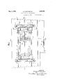
- Fig. 1 is a plan of a removable unit for use in automobiles
- Fig. 2 is an elevation of the unitshown in Fig. 1, and showing, in addition, a portion of a seat attached directly to the supporting frame
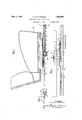
- Fig. 3 is a sectional elevation taken sub stantially along line 33 of Fig. 1, but showing, in addition, a portion of a seat attached to the supporting frame;
- Fig. 4e is a sectional elevationtaken substantially along line H of Fig. 1, but showing, in addition, means for attaching a seat to the supporting frame;
- Fig. 5 is a sectional elevation taken substantially along line 5-5 of Fig. 1, but showing, in addition, a seat attached directly to the supporting frame
- Fig. 6 is a sectional elevation taken substantially along line 6-6 of Fig. 1
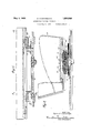
- Fig. 7 is a sectional elevation taken substantially along line 77 of Fig. 5 and showing an operating lever-in the form of a ratchet mechanism
- Fig. 8 is a sectional elevation similar to that shown in Fig. 3, but showing cushioning members disposed between the seat and supporting frame;
- Fig. 9 is a sectional elevation taken, substantially along line 9-9 of Fig. 8.
- the apparatus shown in the drawings comprises a supporting frame 10 supported at its opposite ends in guides 11.'
- the guides 11 comprise upper and lower sheet metal plates 12 and 13 lying in contact with each other adjacent the center and at one side and attached to the floor board unit or base 14 by means of bolts 15.
- the guide plates may be riveted or otherwise attached together at one or more points between the bolts 15.
- the upper plates 12 are provided with upstand ing longitudinally extending flanges which serve as strengthening ribs.
- the central portion of each upper plate 12 is pressed downiii) wardly to form a groove and each lower plate 13 is pressed upwardly along the outside edge so that its upper surface lies in contact with the lower surface of the upper plate 12.
- the inner edge portions of the upper and lower plates 12 and 13 are spaced apart to provide a groove for the reception of the end portions of the supporting frame 10.
- the floor unit 14 comprises five separate boards held together by means of wood cleats attached to their bottom surfaces and extending transversely of the guides. A rectangular-section is removed from an edge portion of one board to provide an opening 18 between two adjacent boards.
- the bolts 15 extend through boards which are spaced apart a distance at least equal to the width of one board and the lower plates 13 are pressed out so that the portions around the holes through which the bolts 15 extend project below the major portion of the lower surface and the guides are supported by the boards through which the bolts extend and are normally spaced above the intermediate boards.
- the guides 11 are similar and interchangeable.
- the frame 10 comprises two similar sheet metal side members 16 and two similar sheet metal end members 17
- the end members 17 are disposed above and rest .upon the side members 16 and the side and end members are held in proper alignment by means of tongues 20 struck from the side members 16 and extending into slots in the end members 17, and by means of downwardly pressed portions 21 of the end members 17. Additional. means in the form of seat bolts 22 attached to and extending through the side members 16 and engaging the walls of slots formed in the end members 17 may be pro vided for holding the side and end members in alignment.
- the outer edge portions of the end members 17 between the side members 16 are pressed down into substantial alignment with the outer ends of the side members 16 and these portions extend with the outer ends of the side members 16 into the grooves formed by the upper and lower guide'plates 12 and 13.
- the side and end members 16 and 17 may be riveted together as at 23.
- the end'edges of the frame 10 are spaced from the vertical walls of the grooves in the guides, and preferably lie in contact only with the inner side edges of the upper surface of the guide plate 13.
- the end members 17 are provided with holes 19 which provide means for attaching cushioning members thereto.
- the portions of the side members 16 adjacent the seat bolts 22 are pressed out to provide supporting surfaces for the seat attaching members at the same elevation as the upper surfaces of the end members 17, as shown, for instance, in Fig. 6.
- the longitudinal edge portions of the rack plate 24 are bent to provide upstanding flanges which are disposed in grooves formed in a plate 25 as shown, for instance, in Fig. 3.
- the plate 25 extends over the opening 18 in the floor board unit and is attached by means of bolts 26 extending through the floor boards to a housing 27 containing a worm 30.
- the worm 30 is mounted on a shaft 31 supported for rotation in suitable bearings in the end walls of the housing 27. Suitable thrust bearings are provided for engaging the end faces of the worm 30.
- a seat 32 may be attached directly to the frame 10 by means of bolts 22 and wood cleats 28 extending longitudinally thereof.
- the shaft 31 extends beneath the floor boards to apoint in front of the seat 32, and it is supported at its forward end in a bearing 33 comprising a suitable bent strap of sheet metal.
- the forward end of the shaft 31 is provided with an operating lever 34.
- the floor board unit is provided with a semi-circular opening adj acent the outer end of the operating lever 34 to permit access thereto.
- a spring clip 38 looks the lever 34 against rotation.
- the operating lever 34 comprises acasing having a handle portion and an enlarged end portion for receiving a ratchet wheel 35.
- the ratchet wheel 35 is preferably rigidly mounted on the shaft 31.
- a ratchet pawl 36 is pivotally attached between its ends to a wall of the casing for reversing movement.
- a reversing lever 37 extends through the handle portion of the casing and is pivotally attached to the pawl.
- the reversing lever 37 is provided with a projection 40 which ex- 7 tends through a slot in the casing wall to permit manipulation.
- a spring 41 is provided for maintaining the pawl in engagement with the ratchet wheel.
- the lever 37 may be manipulated to cause either end of the ratchet pawl to engage the ratchet wheel so that the operating lever 34 may be utilized for rotating the worm shaft in opposite directions.
- the operating lever is preferably so formed that its upper edge lies flush with or slightly below the upper surface of the floor boards when not in use.
- cushioning members 42 are shown disposed between the seat and the supporting frame.
- Each cushioning member comprises a pair of channel-shaped sheet metal members 43 attached together at their end edges by means of bolts 44 to form an annular ring.
- An annular soft rubber core 45 is seated within the annular ring thus formed between the side walls of the channel-shaped members, and an annular sheet metalcore 46 having a grooved outer surface is mounted within the opening in the rubber core.
- the rubber core may be conveniently formed of two U-shaped members.
- One of the channel-shaped members 43 is tached to said housing and said fixed support.
- a sheet metal plate 47 is attached at one end to the inner sheet metal core 46 and at its opposite end to the attaching members 48 carried by the seat 49.
- the upper and lower channel-shaped members 43 are held in fixed positions relatively to one another by means of shims 50 at their ends, and by means of a centrally disposed sleeve 51 and abolt 52.
- the attaching members 48 are formed of wood and extend longitudinally of the seat.
- a seat mounted on the supporting frame 10 may be moved in either direction longitudinally of the body of an automobile in which it may be mounted through proper manipulation of the operating lever 34.
- the plate 25 may also serve to prevent Vertical movement of the frame. Portions of the plate between the center and the grooved portions overlying the upstanding flanges on the rack plate may be bent downwardly to provide curved surfaced ridges in contact with the upper surface of the rack plate. This structure is illustrated in Fig. 3.
- Portions of the end plates 17 of the supporting frame may lie in contact with the inner upstanding flanges on the upper guide plates 12 and these flanges are preferably bent to provide curved contacting surfaces.
- the contacting surfaces between moving parts are preferably curved to provide minimum contact areas and eliminate friction.
- Apparatus constructed in accordance with the invention is simple, efiicient and relatively inexpensive to manufacture. Many of the parts are interchangeable and of such natures that they may be formed without waste.
- the supporting structure is capable of efficiently supporting a double seat so that the entire front seat of an automobile may be made adjustable.
- the adjustable supporting means may be attached to the floor board unit before the floor board unit is placed in the automobile, and the seat proper may be attached to the adjustable supporting means after the assembly has been placed in the automobile.
- a device of the class described comprising a fixed support, spaced guides mounted upon said support, a seat support adjustably mounted upon said guides, a rack mounted upon said seat support and movable therewith, a worm disposed below and engaging said rack, a housing surrounding said worm, and a guiding and restraining member extending over said rack and rigidly at- 2.
- an adjustable seat support a rack rigidly at tached to said seat support, screw means including a worm engaging said rack to move said support, a housing surrounding said screw means, and a plate extending over said rack and rigidly attached to said support and said housing to guide said rack and restrain movement of the rack away from the Worm.
- a pair of spaced guides mounted upon the floor thereof, a movable seat support mounted upon said guides, a rack attached to said support and movable therewith, a shaft rotatably mounted below the floor, a worm rigidly mounted on said shaft and extending through an opening in the floor into engagement with said rack, a housing surrounding said worm, and a metal strap extending over said rack and rigidly attached to said housing.
- a pair of spaced guides mounted upon the floor thereof, a movable seat support mounted upon said guides, a rack rigidly attached to said seat support and movable therewith, a worm mounted for rotation beneath the floor and extending through an openin in the floor int-o engagement with said rac means for rotating said worm to move said rack and support, a housing surrounding said worm and provided with thrust bearings for engaging the end faces of said worm, and a plate extending over said rack and rigidly attached to the floor and housing to guide said rack and restrain movement of the rack away from the worm.
Landscapes
- Engineering & Computer Science (AREA)
- Aviation & Aerospace Engineering (AREA)
- Transportation (AREA)
- Mechanical Engineering (AREA)
- Seats For Vehicles (AREA)
Description
May 3, 1932- G. FLINTERMANN ADJUSTABLE SEAT FOR VEHICLES Filed May 8, 1929 4 Sheets-Sheet 1 n mm ma E m m a In r Q mgaihwwm H 15 ATTORNEYS y 3, 1932- G. FLINTERMANN ADJUSTABLE SEAT FOR VEHICLES 4 Sheets-Sheet 2 Filed May 8, 1929 M NL INVENTOR Qev'hard Flmfermarm BY PM;
HIS ATTORNEYS May 3, 1932. e. FLINTERMANN ADJUSTABLE SEAT FOR VEHICLES Filed May 8, 1929 4 Sheets-Sheet 3 T X x w m w i z l m Ma m T A In I l U P %M.\MN, Y J
G. FLINTERMANN ADJUSTABLE SEAT FOR VEHICLES Filed May 8, 1929 4 Sheets-Sheet 4 INVENTOR M /10707 FlmTermqnn H l5 ATTORNEYS E Y/f7 Q $1 M ///f/ May 3, 1932.
Patented May 3, 1932 UNITED STATES PATET G FFECE ADJUSTABLE SEAT FOR VEHICLES Application filed May 8,
This invention relates to seats and has for an object the provision of improved means for mounting seats. More particularly, the invention contemplates the provision of improved supporting and adjusting means for seats.
In one of its aspects, the invention is particularly applicable to vehicles in which it is desirable to provide adjustable seats for varying the leg room provided. Thus, the invention provides improved means for adjusting the positions of automobile front seats by moving the seats rearwardly and forwardly, or, in opposite directions longitudinally of the automobile body.
Apparatus embodying the invention comprises a supporting frame mounted for sliding movement in guide members disposed adjacent the opposite ends thereof and attached to a suitable supporting base, and means for moving the supporting frame relatively to the guide members. hen the invention is applied to automobiles, the supporting base is preferably a group of floor boards attached together and removable as a unit. The construction and mounting of the guides and frame are such that relatively small contact surfaces are provided and a minimum amount of play is permitted whereby the frame may be easily moved and readily confined to its proper path of travel. The seat proper may be attached directly to the supporting frame, or it may be attached to cushioning members attached to the frame.
In one form of apparatus embodying the invention. a rack is attached to the movable supporting frame in such a manner that it is operatively engaged by a worm rigidly mounted on a shaft supported for rotation in fixed bearings. The worm shaft extends to a convenient point in front of the seat and it is provided adjacent one end with an operating lever. The operating lever is preferably a ratchet mechanism which is so constructed a1 1 d mounted that its upper edge is flush with or is disposed slightlybelow the upper surface of the floor board unit to which the frame guides are attached. The worm is restrained against movement away from the rack by 1929. Serial No. 361,404.
means of a metal strip which extends over and serves as a guide for the rack.
The invention will be better understood from a consideration of the following description in conjunction with the accompanying drawings in which:
Fig. 1 is a plan of a removable unit for use in automobiles;
Fig. 2 is an elevation of the unitshown in Fig. 1, and showing, in addition, a portion of a seat attached directly to the supporting frame Fig. 3 is a sectional elevation taken sub stantially along line 33 of Fig. 1, but showing, in addition, a portion of a seat attached to the supporting frame;
Fig. 4eis a sectional elevationtaken substantially along line H of Fig. 1, but showing, in addition, means for attaching a seat to the supporting frame; I
Fig. 5 is a sectional elevation taken substantially along line 5-5 of Fig. 1, but showing, in addition, a seat attached directly to the supporting frame Fig. 6 is a sectional elevation taken substantially along line 6-6 of Fig. 1
Fig. 7 is a sectional elevation taken substantially along line 77 of Fig. 5 and showing an operating lever-in the form of a ratchet mechanism; 7
Fig. 8 is a sectional elevation similar to that shown in Fig. 3, but showing cushioning members disposed between the seat and supporting frame; and
. Fig. 9 is a sectional elevation taken, substantially along line 9-9 of Fig. 8.
The apparatus shown in the drawings comprises a supporting frame 10 supported at its opposite ends in guides 11.' The guides 11 comprise upper and lower sheet metal plates 12 and 13 lying in contact with each other adjacent the center and at one side and attached to the floor board unit or base 14 by means of bolts 15. The guide plates may be riveted or otherwise attached together at one or more points between the bolts 15. The upper plates 12 are provided with upstand ing longitudinally extending flanges which serve as strengthening ribs. The central portion of each upper plate 12 is pressed downiii) wardly to form a groove and each lower plate 13 is pressed upwardly along the outside edge so that its upper surface lies in contact with the lower surface of the upper plate 12. The inner edge portions of the upper and lower plates 12 and 13 are spaced apart to provide a groove for the reception of the end portions of the supporting frame 10. The floor unit 14 comprises five separate boards held together by means of wood cleats attached to their bottom surfaces and extending transversely of the guides. A rectangular-section is removed from an edge portion of one board to provide an opening 18 between two adjacent boards. The bolts 15 extend through boards which are spaced apart a distance at least equal to the width of one board and the lower plates 13 are pressed out so that the portions around the holes through which the bolts 15 extend project below the major portion of the lower surface and the guides are supported by the boards through which the bolts extend and are normally spaced above the intermediate boards. The guides 11 are similar and interchangeable.
The frame 10 comprises two similar sheet metal side members 16 and two similar sheet metal end members 17 The end members 17 are disposed above and rest .upon the side members 16 and the side and end members are held in proper alignment by means of tongues 20 struck from the side members 16 and extending into slots in the end members 17, and by means of downwardly pressed portions 21 of the end members 17. Additional. means in the form of seat bolts 22 attached to and extending through the side members 16 and engaging the walls of slots formed in the end members 17 may be pro vided for holding the side and end members in alignment. The outer edge portions of the end members 17 between the side members 16 are pressed down into substantial alignment with the outer ends of the side members 16 and these portions extend with the outer ends of the side members 16 into the grooves formed by the upper and lower guide'plates 12 and 13. The side and end members 16 and 17 may be riveted together as at 23. The end'edges of the frame 10 are spaced from the vertical walls of the grooves in the guides, and preferably lie in contact only with the inner side edges of the upper surface of the guide plate 13. The end members 17 are provided with holes 19 which provide means for attaching cushioning members thereto. The portions of the side members 16 adjacent the seat bolts 22 are pressed out to provide supporting surfaces for the seat attaching members at the same elevation as the upper surfaces of the end members 17, as shown, for instance, in Fig. 6.
A sheet metal rack plate 24, having rack teeth formed therein by pressing, is mounted on and rigidly attached to the side members 16 between these members and the floor boards and extends parallel with the guides 11. The longitudinal edge portions of the rack plate 24 are bent to provide upstanding flanges which are disposed in grooves formed in a plate 25 as shown, for instance, in Fig. 3. The plate 25 extends over the opening 18 in the floor board unit and is attached by means of bolts 26 extending through the floor boards to a housing 27 containing a worm 30.
The worm 30 is mounted on a shaft 31 supported for rotation in suitable bearings in the end walls of the housing 27. Suitable thrust bearings are provided for engaging the end faces of the worm 30. A seat 32 may be attached directly to the frame 10 by means of bolts 22 and wood cleats 28 extending longitudinally thereof. The shaft 31 extends beneath the floor boards to apoint in front of the seat 32, and it is supported at its forward end in a bearing 33 comprising a suitable bent strap of sheet metal. The forward end of the shaft 31 is provided with an operating lever 34. The floor board unit is provided with a semi-circular opening adj acent the outer end of the operating lever 34 to permit access thereto. A spring clip 38 looks the lever 34 against rotation.
The operating lever 34 comprises acasing having a handle portion and an enlarged end portion for receiving a ratchet wheel 35. The ratchet wheel 35 is preferably rigidly mounted on the shaft 31. A ratchet pawl 36 is pivotally attached between its ends to a wall of the casing for reversing movement. A reversing lever 37 extends through the handle portion of the casing and is pivotally attached to the pawl. The reversing lever 37 is provided with a projection 40 which ex- 7 tends through a slot in the casing wall to permit manipulation. A spring 41 is provided for maintaining the pawl in engagement with the ratchet wheel. The lever 37 may be manipulated to cause either end of the ratchet pawl to engage the ratchet wheel so that the operating lever 34 may be utilized for rotating the worm shaft in opposite directions. The operating lever is preferably so formed that its upper edge lies flush with or slightly below the upper surface of the floor boards when not in use.
In Figs. 8 and 9 cushioning members 42 are shown disposed between the seat and the supporting frame. Each cushioning member comprises a pair of channel-shaped sheet metal members 43 attached together at their end edges by means of bolts 44 to form an annular ring. An annular soft rubber core 45 is seated within the annular ring thus formed between the side walls of the channel-shaped members, and an annular sheet metalcore 46 having a grooved outer surface is mounted within the opening in the rubber core. The rubber core may be conveniently formed of two U-shaped members.
One of the channel-shaped members 43 is tached to said housing and said fixed support.
attached to each of the end members 17 of the supporting frame 10. A sheet metal plate 47 is attached at one end to the inner sheet metal core 46 and at its opposite end to the attaching members 48 carried by the seat 49. The upper and lower channel-shaped members 43 are held in fixed positions relatively to one another by means of shims 50 at their ends, and by means of a centrally disposed sleeve 51 and abolt 52. The attaching members 48 are formed of wood and extend longitudinally of the seat.
A seat mounted on the supporting frame 10 may be moved in either direction longitudinally of the body of an automobile in which it may be mounted through proper manipulation of the operating lever 34. The plate 25, contacting with the upstanding flanges on the rack plate 24:, serves as a guide for the frame 10 and confines it to its proper path of travel, thus preventing side movement of the frame with resulting jam ming.
The plate 25 may also serve to prevent Vertical movement of the frame. Portions of the plate between the center and the grooved portions overlying the upstanding flanges on the rack plate may be bent downwardly to provide curved surfaced ridges in contact with the upper surface of the rack plate. This structure is illustrated in Fig. 3.
Portions of the end plates 17 of the supporting frame may lie in contact with the inner upstanding flanges on the upper guide plates 12 and these flanges are preferably bent to provide curved contacting surfaces. The contacting surfaces between moving parts are preferably curved to provide minimum contact areas and eliminate friction.
Apparatus constructed in accordance with the invention is simple, efiicient and relatively inexpensive to manufacture. Many of the parts are interchangeable and of such natures that they may be formed without waste. The supporting structure is capable of efficiently supporting a double seat so that the entire front seat of an automobile may be made adjustable. The adjustable supporting means may be attached to the floor board unit before the floor board unit is placed in the automobile, and the seat proper may be attached to the adjustable supporting means after the assembly has been placed in the automobile.
I claim:
1. A device of the class described comprising a fixed support, spaced guides mounted upon said support, a seat support adjustably mounted upon said guides, a rack mounted upon said seat support and movable therewith, a worm disposed below and engaging said rack, a housing surrounding said worm, and a guiding and restraining member extending over said rack and rigidly at- 2. In a device of the class described, an adjustable seat support, a rack rigidly at tached to said seat support, screw means including a worm engaging said rack to move said support, a housing surrounding said screw means, and a plate extending over said rack and rigidly attached to said support and said housing to guide said rack and restrain movement of the rack away from the Worm.
3. In an automobile, a pair of spaced guides mounted upon the floor thereof, a movable seat support mounted upon said guides, a rack attached to said support and movable therewith, a shaft rotatably mounted below the floor, a worm rigidly mounted on said shaft and extending through an opening in the floor into engagement with said rack, a housing surrounding said worm, and a metal strap extending over said rack and rigidly attached to said housing.
4c. In an automobile, a pair of spaced guides mounted upon the floor thereof, a movable seat support mounted upon said guides, a rack rigidly attached to said seat support and movable therewith, a worm mounted for rotation beneath the floor and extending through an openin in the floor int-o engagement with said rac means for rotating said worm to move said rack and support, a housing surrounding said worm and provided with thrust bearings for engaging the end faces of said worm, and a plate extending over said rack and rigidly attached to the floor and housing to guide said rack and restrain movement of the rack away from the worm.
In testimony whereof I aflix my signature.
GERI-IARD FLINTERMANN.
Priority Applications (1)
| Application Number | Priority Date | Filing Date | Title |
|---|---|---|---|
| US361404A US1856950A (en) | 1929-05-08 | 1929-05-08 | Adjustable seat for vehicles |
Applications Claiming Priority (1)
| Application Number | Priority Date | Filing Date | Title |
|---|---|---|---|
| US361404A US1856950A (en) | 1929-05-08 | 1929-05-08 | Adjustable seat for vehicles |
Publications (1)
| Publication Number | Publication Date |
|---|---|
| US1856950A true US1856950A (en) | 1932-05-03 |
Family
ID=23421900
Family Applications (1)
| Application Number | Title | Priority Date | Filing Date |
|---|---|---|---|
| US361404A Expired - Lifetime US1856950A (en) | 1929-05-08 | 1929-05-08 | Adjustable seat for vehicles |
Country Status (1)
| Country | Link |
|---|---|
| US (1) | US1856950A (en) |
Cited By (2)
| Publication number | Priority date | Publication date | Assignee | Title |
|---|---|---|---|---|
| US4641806A (en) * | 1984-06-15 | 1987-02-10 | A. M. Cousin & Cie | Screw slide system having a manual or electric control or the like |
| USRE35485E (en) * | 1992-06-11 | 1997-04-01 | Atwood Industries, Inc. | Uni-brace |
-
1929
- 1929-05-08 US US361404A patent/US1856950A/en not_active Expired - Lifetime
Cited By (2)
| Publication number | Priority date | Publication date | Assignee | Title |
|---|---|---|---|---|
| US4641806A (en) * | 1984-06-15 | 1987-02-10 | A. M. Cousin & Cie | Screw slide system having a manual or electric control or the like |
| USRE35485E (en) * | 1992-06-11 | 1997-04-01 | Atwood Industries, Inc. | Uni-brace |
Similar Documents
| Publication | Publication Date | Title |
|---|---|---|
| US7717490B2 (en) | Seat slide device for vehicle | |
| US5447352A (en) | Seat slide mechanism for vehicles | |
| US2646333A (en) | Sliding drawer construction | |
| CN107921890A (en) | Seat slide device for vehicle | |
| CN102227334A (en) | Positive engagement locking system for vehicle seats | |
| US2481970A (en) | Horizontally adjustable footrail | |
| US4500062A (en) | Adjustable seat leveling mechanism | |
| US1856950A (en) | Adjustable seat for vehicles | |
| DE102013105068A1 (en) | Sunroof device | |
| US2543509A (en) | Straight pull brake lever structure | |
| US2534350A (en) | Guide for drawers or shelves | |
| US2134135A (en) | Adjustable seat for vehicles | |
| US3372954A (en) | Sliding roofs of vehicles and control and locking device therefor | |
| US2001999A (en) | Seat adjuster | |
| US2100546A (en) | Automobile seat track construction | |
| US2154294A (en) | Locking mechanism for adjustable seats | |
| US1806014A (en) | Adjustable seat for vehicles | |
| US2635481A (en) | Brake actuator | |
| US1887077A (en) | Adjustable seat | |
| US3052443A (en) | Manual seat adjuster | |
| US964825A (en) | Roller-skate. | |
| JP6667947B2 (en) | Sheet under tray support structure | |
| JP3151944B2 (en) | Seat slide device | |
| US1890048A (en) | Adjustable seat | |
| US1943550A (en) | Seat control mechanism |