EP0168258B1 - Loop transmission system - Google Patents
Loop transmission system Download PDFInfo
- Publication number
- EP0168258B1 EP0168258B1 EP85304992A EP85304992A EP0168258B1 EP 0168258 B1 EP0168258 B1 EP 0168258B1 EP 85304992 A EP85304992 A EP 85304992A EP 85304992 A EP85304992 A EP 85304992A EP 0168258 B1 EP0168258 B1 EP 0168258B1
- Authority
- EP
- European Patent Office
- Prior art keywords
- loop
- state
- node
- signal
- circuit
- Prior art date
- Legal status (The legal status is an assumption and is not a legal conclusion. Google has not performed a legal analysis and makes no representation as to the accuracy of the status listed.)
- Expired - Lifetime
Links
Images


Classifications
-
- H—ELECTRICITY
- H04—ELECTRIC COMMUNICATION TECHNIQUE
- H04M—TELEPHONIC COMMUNICATION
- H04M7/00—Arrangements for interconnection between switching centres
- H04M7/14—Arrangements for interconnection between switching centres in systems involving main and subordinate switching centres
-
- H—ELECTRICITY
- H04—ELECTRIC COMMUNICATION TECHNIQUE
- H04L—TRANSMISSION OF DIGITAL INFORMATION, e.g. TELEGRAPHIC COMMUNICATION
- H04L12/00—Data switching networks
- H04L12/28—Data switching networks characterised by path configuration, e.g. LAN [Local Area Networks] or WAN [Wide Area Networks]
- H04L12/42—Loop networks
- H04L12/437—Ring fault isolation or reconfiguration
-
- H—ELECTRICITY
- H04—ELECTRIC COMMUNICATION TECHNIQUE
- H04L—TRANSMISSION OF DIGITAL INFORMATION, e.g. TELEGRAPHIC COMMUNICATION
- H04L12/00—Data switching networks
- H04L12/28—Data switching networks characterised by path configuration, e.g. LAN [Local Area Networks] or WAN [Wide Area Networks]
- H04L12/42—Loop networks
Definitions
- the present invention relates to a loop transmission system which includes a plurality of loop-connected node stations.
- LAN local area network
- a loop transmission system includes a plurality of node stations loop-connected one by one by a communication line, for example, an optical fiber cable, and a plurality of terminal devices and a plurality of processors which may be connected to corresponding node stations.
- the node stations connect the terminal devices or the processors to the communication line or disconnect the terminal devices or the processors from the communication line.
- the node stations are chain-connected. Accordingly the loop transmission system can fail completely if one of the node stations fails or the communication line breaks down, resulting in a breakdown of the loop path.
- two communication lines may be provided: a master loop line and sub-loop line for connecting adjacent node stations.
- master (or an upper) and slave (or a lower) loop-back circuits in each node station In a normal condition a loop-back circuit is connected to the separate master and sub-loop lines introduced therein for passing signals on the lines.
- the loop-back circuit for example, the master loop-back circuit, connects the master loop line and sub-loop line to form a loop-back ON state and, accordingly, disconnect (separate) the node station in question and an adjacent node station positioned at a preceding position thereof.
- a transmission signal on the main loop line output from the preceding node station cannot reach the node station in question.
- a transmission signal on the sub-loop line output from an adjacent node station positioned at a following position thereof can be returned to the following node station through the main loop line connected to the sub-loop line at the master loop-back circuit. This helps transmission loop reconfiguration in the loop transmission system.
- token-passing system without a supervisory station
- a Token-Ring Architecture for Local-Area Networks by D.W. Andrews and G.D. Schultz, March 8, 1982, IEEE Project 802 on Local Area Networks.
- token means polling information.
- the loop transmission system of the present invention pertains to this type of loop transmission system.
- the token-passing systems of the prior art suffer from the disadvantage of low availability and difficulty of system maintenance.
- US-A-4,320,508 discloses a ring-configured network of multiple inter-communicating data stations in which each data station includes a fault sensing circuit, a test-pulse generating circuit and a switching circuit as well as a transmitter circuit and a receiver circuit.
- the test pulse generating circuit responds to a sensed fault to transmit test signals sequentially, in opposite directions along the ring. In combination with the fault sensing circuit, these indicate the direction of any fault and terminate the line in the direction of the fault at the characteristic impedance of the line. Thus, normal communications can continue between the stations despite the fault.
- the present invention relates to a loop transmission system which includes a plurality of loop-connected node stations, each station including two loop-back circuits, in particular to a token-passing type loop transmission system without a supervisory loop control apparatus therein, which can detect and identify a fault point therein and can construct a loop transmission line not including the fault point. That is, the present invention relates to a loop transmission system having an automatic loop (or link) configuration control (ALCC) means.
- ACC automatic loop (or link) configuration control
- a loop transmission system comprising:
- first and second transmission lines provided in parallel with each other, each operable to form a separate closed loop transmission line, and respectively operable to transmit signals in opposite directions;
- each of said plurality of node means comprising:
- first and second loop-back means respectively provided at first and second ends of said node means, and respectively operable to connect said first and second paths at respective ends of said node means;
- first loop-back means is operable to connect said first path with said first transmission line and said second path with said second transmission line at said first end of said node means
- second loop-back means is operable to connect said first path with said first transmission line and said second path with said second transmission line at said second end of said node means
- a first automatic loop-back means for automatically placing said first loop-back means in an automatic loop-back state wherein said first and second paths are connected with each other at said first end of said node means, when a signal from said first transmission line is not detected at said first end;
- a second automatic loop-back means for automatically placing said second loop-back means in an automatic loop-back state wherein said first and second paths are connected with each other at said second end of said node means, when a signal from said second transmission line is not detected at said second end;
- an abnormal state detecting means for detecting an abnormal state in a signal transmitted on said first path, where said abnormal state is determined based on whether or not said first path is in a complete loop;
- a first voluntary loop-back means for voluntarily placing said first loop-back means in a voluntary loop-back state, when said abnormal state is detected in the node means when said first loop-back means is in neither of said automatic and voluntary loop-back states;
- a second voluntary loop-back means for voluntarily placing said second loop-back means in a voluntary loop-back state, when said abnormal state is detected in the node means when said first loop-back means is in one of said automatic and voluntary loop-back states;
- a loop-back release try means for trying to release said automatic loop-back state in said first loop-back means when said first loop-back means is in said automatic loop-back state, and said second loop-back means is in said voluntary loop-back state;
- a first restoring means for restoring said first loop-back means from an automatic or voluntary loop-back state when reappearance of a signal from said first transmission line is detected at said first end of the node means after disappearance of the signal;
- a second restoring means for restoring said second loop-back means from an automatic or voluntary loop-back state when reappearance of a signal from said second transmission line is detected at said second end of the node means after disappearance of the signal.
- An embodiment of the present invention can provide a loop transmission system which can automatically detect a fault therein, identify a fault point, remove the fault point from the loop transmission system, and construct an available loop transmission system.
- An embodiment of the present invention can provide a loop transmission system with increased availability of operation.
- An embodiment of the present invention can provide a loop transmission system with easy maintenance.
- Fig. 1 is a block diagram of a previously proposed transmission system
- Fig. 2 is a circuit diagram of an embodiment of a node station in accordance with the present invention.
- Fig. 3 is a circuit diagram of a loop-back circuit shown in Fig. 2;
- Figs. 4a to 4d are views illustrating a transmission operation between node stations as shown in Fig. 2;
- Fig. 5 is a view of a transmission signal format
- Fig. 6 is a flow chart explaining the operation of the node station shown in Fig. 2;
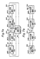
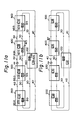
- Figs. 7a to 7g are views showing an automatic loop configuration control operation in a loop transmission system including node stations as shown in Fig. 2 for a first type of fault;
- Figs. 8a to 8d are views showing an automatic loop configuration control operation for a second type of fault
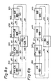
- Figs. 9a to 9i are views showing an automatic loop configuration control operation for a third type of fault
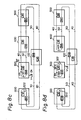
- Figs. 10a to 10f are views showing an automatic loop configuration control operation for a fourth type of fault.
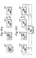
- Figs. 11a to 11c are views showing an automatic loop configuration control operation for a fifth type of fault.
- Figure 1 is a block diagram of a previously proposed loop transmission system.
- the loop transmission system includes a plurality of node stations (NS1 to NS3) 100a to 300a which are loop (link)-connected by means of duplicate communication lines, i.e., a main loop line 40 and a sub-loop line 50.
- the loop lines 40 and 50 are optical fiber cables.
- the loop transmission system also includes a plurality of ring stations (RS) 11 to 13, 21, 22, and 31, which may be "in-line" in the corresponding node stations.
- RS ring stations
- the node station 100a consists of opto-electrical (O/E) converters 101 and 102, electro-optical (E/O) converters 103 and 104, ring station switching circuits 111 to 113, a master (or upper) loop-back circuit 131, a slave (or lower) loop-back circuit 132, and a loop monitor circuit 130.
- the other node stations 200a and 300a have the same construction as the node station 100a.
- the ring stations 11 and 13 are "in-line" in the main loop line 40 at the node station 100a. However, the ring station 12 is bypassed from the main loop line 40. The above selection of the ring stations is effected by the ring station switching circuits 111 to 113. Similarly, the ring stations 21, 22, and 31 are connected to the main loop line 40.
- the loop monitor circuit 130 monitors the state of the main loop line 40 and detects disappearance of the frame signal, reproduces the frame signal, and transmits an error-notice-frame, i.e., a beacon-frame signal, when reproduction of the frame signal fails.
- the master loop-back circuit 131 receives a signal which is converted from an optical signal to an electrical signal at the O/E converter 101 or a carrier on the main loop line 40.
- the master loop-back circuit 131 detects loss of the above signal, the master loop-back circuit 131 effects a loop-back, that is, the main loop line and the sub-loop line are connected in the master loop-back circuit 131.
- the slave loop-back circuit 132 receives a signal or a carrier on the sub-loop line 50 and effects a loop-back as mentioned above.
- the loop monitor circuit in the node station 200a fails, the transmission signal on the main loop line 40 is lost at the node station 200a.
- the following node station 300a detects the disappearance of the frame signal included in the transmission signal.
- the loop monitor circuit in the node station 300a tries to reproduce the frame signal, that is, to output the frame signal to the node station 100a through the main loop line 40.
- the above reproduced frame signal is extinguished at the node station 200a including the failed loop monitor circuit.
- the node station 300a recognizes the failure of the frame signal reproduction and then outputs the beacon frame signal to the following node station 100a through the main loop line 40.
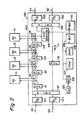
- FIG. 2 is a circuit diagram of an embodiment of a node station in accordance with the present invention.
- the node station (NS1) 100 in Fig. 2 corresponds to the node stations 100a to 300a in Fig. 1, however, differs in circuit configuration and functions. However, the loop construction of the system corresponds to that shown in Fig 1.
- the node station 100 includes O/E converters 101 and 102, E/O converters 103 and 104, a master (or upper) loop-back circuit 121, and a slave (or lower) loop-back circuit 122.
- the node station 100 also includes a ring control circuit (RCS) consisting of a microprocessor unit (MPU) 106, a read-only memory (ROM) 107, a random-access memory (RAM) 108, a transmission data store buffer memory 109, a reception data store buffer memory 110, and a loop monitoring circuit 105.
- MPU microprocessor unit
- ROM read-only memory
- RAM random-access memory
- the node station 100 further includes a series-connected buffer memory 111, switching circuit 116, buffer memory 112, switching circuit 117, buffer memory 113, switching circuit 118, buffer memory 114, and switching circuit 119, as shown in Fig. 2, between the master loop-back circuit 121 and the loop monitoring circuit 105.
- the node station 100 includes a buffer memory 115 between the master and the slave loop-back circuits 121 and 122.
- the node station 100 also includes a system clock generator 120 for activating the above circuit elements.
- Ring stations (RS1 to RS4) 11 to 14 are connected to the switching circuits 116 to 119. Each of the ring stations 11 to 14 may be "in line" in the main loop line 40 by the corresponding switching circuit. Each of the buffer-memories 111 to 114 temporarily stores data for the corresponding ring station.
- the O/E converter 101 receives an optical signal on the main loop line 40 and converts it to an electrical signal.
- the O/E converter 102 receives an optical signal on the sub-loop line 50 and converts it to an electrical signal.
- the E/O converters 103 and 104 convert electrical signals to optical signals on the loop lines 40 and 50.
- FIG. 3 is a specific circuit diagram of the slave loop-back circuit 122.
- the slave loop-back circuit 122 includes an OR gate 122a, a delay-type flip-flop (D-F/F) 122b, an inverter 122c, and a clock extraction circuit 122d provided with an oscillator 122e.
- the slave loop-back circuit 122 also includes a data multiplexer 122f and a clock signal multiplexer 122g.
- the slave loop-back circuit 122 receives at least in one mode of operation, a clock signal S-CLK A , data signal S-DATA A , and a voluntary loop-back indication signal S-VLBI from the loop monitor circuit 105.
- the data signal S-DATA A is supplied to a data input terminal (DT) of the E/O converter 103 and the multiplexer 122f.
- the clock signal S-CLK A is supplied to the multiplexer 122g.
- the voluntary loop-back indication signal S-VLBI is supplied to a stop terminal (STP) of the E/O converter 103 through the OR gate 122a, thus stopping the conversion of the signal in the E/O converter 103.
- the voluntary loop-back indication signal S-VLBI is also supplied to the inverter 122c and then to a clear terminal (CLR) of the D-F/F 122b, thus clearing the D-F/F 122b.
- the O/E converter 102 outputs a data signal, which is received as an optical signal on the sub-loop line 50 and is converted into an electrical signal, at an output terminal (DT) thereof to the clock extraction circuit 122d.
- the clock signal S-CLK E extracted at the clock extraction circuit 122d is supplied to the multiplexer 122g. Simultaneously, the clock extraction circuit 122d extracts a data signal from the data signal output from the O/E converter 102 and outputs it to the multiplexer 122f.
- the O/E converter 102 outputs a no-carrier signal S-NCRY.
- the no-carrier signal S-NCRY is supplied to a clock terminal (CK) at the D-F/F 122b.
- a delay input terminal (D) at the D-F/F 122b receives a constant voltage V c , thus the D-F/F 122b is set in response to the no-carrier signal S-NCRY.
- An output signal at an output terminal (Q) of the D-F/F 122b is supplied to the stop terminal (STP) of the E/O converter 103.
- the output signal at the D-F/F 122b indicates an automatic loop-back operation, thus is named an "automatic loop-back signal S-ALB”.
- the output signal of the OR gate 122a is supplied to the multiplexers 122f and 122g.
- the output signal in question is low level.
- the data signal S-DATA E and the clock signal S-CLK E from the clock extraction circuit 122d are selected at the multiplexers 122f and 122g and supplied to the main loop-back circuit 121 through the buffer memory 115.
- the signal output from the OR gate 122a is high level, with a resultant selection of the data signal S-DATA A and the clock signal S-CLK A , as a selected data signal S-DATA B and a selected clock signal S-CLK B , at the multiplexers 122f and 122g.
- the master loop-back circuit 121 has a similar construction to the slave loop-back circuit 122. Accordingly, the above explanation of the operation of the slave loop-back circuit 122 can be applied to the master loop-back circuit 121.
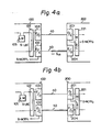
- Figures 4a to 4d are views explaining basic loop-back operation between the node station 100 and a node station 200, which station 200 has the same construction as the node station 100.
- Figures 4a to 4d show only the lower side circuits of the node station 100, i.e., the loop monitor circuit 105, the slave loop-back circuit 122, the E/O converter 103, and the O/E converter 102, and the upper side circuits of the node station 200, i.e., an O/E converter 201, an E/O converter 204, and a master loop-back circuit 221.
- the E/O converter 103 and the O/E converter 201 are connected by means of the main loop line 40.
- the O/E converter 102 and the E/O converter 204 are also connected by means of the sub-loop line 50.
- the slave loop-back circuit 122 and the master loop-back circuit 221 are in a loop-back OFF state.
- Figure 4a indicates the loop-back circuit 122 is in the loop-back ON state.
- the loop-back circuit 221 When a power source of the node station 200 is turned on, when the node station 200 receives a loop-back release instruction frame signal, or when an operator demands the loop-back release operation through an operator panel (not shown) on the node station 200, the loop-back circuit 221 is rendered in a loop-back release state (or loop-back OFF state) as shown in Fig. 4a.
- the node station 200 outputs a light signal S LQ on the sub-loop line 50 and waits for an answer signal.
- the node station 100 releases the loop-back ON state in the loop-back circuit 122, then outputs an answer light signal S LA on the main loop line 40.
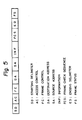
- Figure 5 is an example of a transmission data format in accordance with a "token" standard of IEEE 802.5.
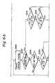
- FIG. 6 is a flow chart showing an automatic loop (link) configuration control (ALCC) operation in the ring control circuit (RCS), which consists of the MPU 106, the ROM 107 storing a control program, the RAM 108 for temporarily storing data, the transmission data store buffer memory 109, the reception data store buffer memory 110, and the loop monitor circuit 105.
- ALCC automatic loop configuration control
- the operation of the RCS is as follows:
- the loop transmission system includes five node stations (NS1 to NS5) 100 to 500 which are link connected by the main and sub-loop lines 40 and 50.
- NS1 to NS5 node stations
- LM loop monitor circuits
- BM buffer memories
- a fault occurs at a fault point FP between the node stations 300 and 400.
- the fault may be a breakdown of the sub-loop line 50 between the above node stations 300 and 400, distortion of a light emitting diode (LED) in the E/O converter (not shown) in the node station 400, or the like.
- the fault results in extinction (loss) of data from the node station 300.
- the above failure cannot normally be detected in a normal operation mode, because the data has not been is not transmitted on the sub-loop line 50 during normal operation.
- the automatic loop-back operation in the ring control circuit in the node station as mentioned before with reference to Fig. 6 may be effected in the node stations 200 and 500.
- the ring control circuit in the node station 200 places the master loop-back circuit 221 in the loop-back ON state, which means connection of the master and sub-loop lines 40 and 50.
- the slave loop-back circuit 522 is rendered in the loop-back ON state.
- the data may be transmitted on the sub-loop line 50.
- the data on the sub-loop line 50 is obviously extinguished at the fault point FP.
- the node station 200 detects extinction of the free "token” signal, then starts the operation for transmitting the monitor recovery frame signal as mentioned with regard to step S002 in Fig. 6.
- the monitor recovery frame signal is also extinguished at the fault point FP, with a resultant failure of the frame signal reproduction.
- the ring control circuit in the node station 200 outputs a beacon frame signal on the sub-loop line 50.
- the beacon frame signal is also extinguished at the fault point FP.
- the ring control circuit in the node station 200 detects the failure of the recovery operation on the basis of retransmission of the beacon frame signal.
- the node station 200 checks the master loop-back circuit 221. In this case, the master loop-back circuit 221 is already in a loop-back ON state.
- the node station checks the slave loop-back circuit 222 and outputs the voluntary loop-back indi cation signal to the slave loop-back circuit, since the state in the slave loop-back circuit 222 is a loop-back OFF state.
- the slave loop-back circuit 222 is rendered into the voluntary loop-back ON state.
- the node station 200 stands as an isolation system which is degenerated and has a closed loop line therein.
- the node station 300 cannot receive the light signal or the carrier from the node station 200.
- the node station 300 places the master loop-back circuit in the automatic loop-back ON state.
- the node station 300 detects the extinction of the frame signal, as similar to the node station 200, and starts the operation for transmitting the monitor recovery frame signal to the node station 400.
- the monitor recovery frame signal is extinguished at the fault point FP, with a resultant failure of the frame signal reproduction.
- the node station 300 outputs a beacon frame signal on the sub-loop line 50. However, the beacon frame signal is extinguished at the fault point FP.
- the ring control circuit in the node station 200 transmits the beacon frame signal.
- the beacon frame signal passes through a closed loop line in the node station 200, resulting in reception of the beacon frame signal at the loop monitor circuit (LM) 205.
- the ring control circuit in the node station 200 investigates the state of the master loop-back circuit 221.
- the master loop-back circuit 221 is in the automatic loop-back ON state.
- the ring control circuit tries to release the loop-back ON state of the master loop-back circuit 221, as shown in Fig. 7d.
- the ring control circuit in the node station 300 investigates the state of the master loop-back circuit 321 therein.
- the state is the loop-back ON.
- the ring control circuit investigates the state of the slave loop-back circuit 322 therein.
- the state is the loop-back OFF. Accordingly, the ring control circuit outputs a voluntary loop-back indication signal to the slave loop-back circuit, resulting in a voluntary loop-back ON state of the slave loop-back circuit 322.
- the node station 300 has a closed loop line therein.
- the node station 400 cannot receive the light signal or the carrier on the main loop line 40. Therefore, the ring control circuit in the node station 400 outputs an automatic loop-back indication signal to the master loop-back circuit 421, resulting in an automatic loop-back ON state of the master loop-back circuit 421.
- the node station 200 recognizes a failure of the release of the loop-back on the master loop-back circuit 221, because the slave loop-back circuit 522 in the node station 500 is in a loop-back ON state. Then, the master loop-back circuit 221 is again rendered into the automatic loop-back ON state, resulting in reformation of a closed loop line therein.
- the ring control circuit in the node station 300 checks the state of the master loop-back circuit 321. The state is the automatic loop-back ON. Then, the ring control circuit outputs a release loop-back ON signal to the master loop-back circuit 321, resulting in release of the loop-back ON state in the master loop-back circuit 321.
- the node station 200 may receive the light signal on the sub-loop line 50 from the node station 300, whereby the ring control circuit in the node station 200 outputs a release loop-back signal to the slave loop-back circuit 222, resulting in release of the loop-back state of the slave loop-back circuit 222.
- the ring control circuit in the node station 100 outputs a light signal on the sub-loop line 50 through the slave loop-back circuit 122 and the E/O converter 103 shown in Figs. 2 and 3.
- the node station 500 receives the above light signal on the sub-loop line 50, whereupon the ring control circuit therein outputs a loop-back release signal to the slave loop-back circuit 522 therein, with a resultant release of the loop-back in the slave loop-back circuit 522. Consequently, the node station 100 and the node station 500 are again connected.
- the ring control circuit in the recovered node station 100 outputs the light signal on the sub-loop line 50 through the master loop-back circuit 121 and the E/O converter 104 shown in Fig. 2.
- the node station 200 also receives the above light signal.
- the ring control circuit in the node station 200 outputs a loop-back release signal to the master loop-back circuit 221, resulting in release of the loop-back in the master loop-back circuit 221. Consequently, the node station 100 and the node station 200 are also again connected.
- the fault point FP is found and removed from the transmission loop in the loop transmission system.
- the loop transmission system is reconfigured as shown in Fig. 7g and is operable without reduction of performance.
- the fault occurs on the main loop line 40 in the node station 300.
- the fault may be caused by failure of a clock signal for buffer memories, such as the buffer memories 111 to 114 in Fig. 2 for ring stations, such as the ring stations 11 to 14 in Fig. 2, connected to the node station 300, breakdown of the main loop line in the node station 300, failure of ring station switching circuits, such as the circuits 116 to 119 in Fig. 2, or other trouble.
- the data frame signal cannot pass through the main loop line 40.
- the ring control circuit in the node station 300 detects extinction of the free "token" and starts a monitor recovery operation as set forth above. However, the transmitted monitor recovery frame signal is extinguished at the fault point FP in the node station 300, resulting in failure of the monitor recovery operation.
- the ring control circuit in the node station 300 starts transmission of the beacon frame signal BF.
- the beacon frame signal is also extinguished at the fault point FP, thus does not reach the ring control circuit.
- the ring control circuit in the node station 300 checks the loop-back state of the master loop-back circuit in the node station 300. In this case, the loop-back state is OFF.
- the ring control circuit in the node station 300 places the master loop-back circuit 321 in a voluntary loop-back ON state, clears the counter of the beacon frame transmission number, and outputs the beacon frame signal. Nevertheless, the beacon frame signal is still extinguished at the fault point FP in the node station 300.
- the ring control station in the node station 200 places the slave loop-back circuit 222 in the automatic loop-back ON state.
- the ring control circuit in the node station 300 detects the failure of the above recovery operation (transmission of the beacon frame signal).
- the ring control circuit again checks the loop-back state of the master loop-back circuit 321.
- the loop-back state is already the loop-back ON state.
- the ring control circuit checks the loop-back state of the slave loop-back circuit 322.
- the state of the slave loop-back circuit 322 is the loop-back OFF state.
- the ring control circuit places the slave loop-back circuit 322 in the loop-back ON state, resulting in a closed loop line therein.
- the ring control circuit continues to transmit the beacon frame signal.
- the ring control circuit in the node station 400 outputs the monitor recovery frame signal on the main loop line 40.
- the monitor recovery frame signal is returned to the node station 400 through, on the main loop line 40, the node stations 500, 100, and 200, in that order and, on the sub-loop line 50, the node stations 200, 100, and 500.
- Fig. 9a for example the loop monitor circuit 305 in the ring control circuit in the node station 300 fails.
- the ring control circuit in the node station 400 detects extinction of the frame signal on the main loop line 40 and starts the monitor recovery operation. However, the monitor recovery frame signal transmitted from the node station 400 is extinguished at the fault point FP, that is, the loop monitor circuit 305 in the node station 300, resulting in failure of the monitor recovery operation.
- the ring control circuit in the node station 400 outputs the beacon frame signal on the main loop line 40. The beacon frame signal is also extinguished at the fault point FP, and thus cannot reach the ring control circuit in the node station 400.
- the ring control circuit in the node station 400 checks the master loop-back circuit 421 in the loop-back OFF state and places the master loop-back circuit 421 in the voluntary loop-back ON state. After that, the ring control circuit of the node station 400 again outputs the beacon frame signal on the main loop line 40. The beacon frame signal is also extinguished at the fault point FP in the node station 300.
- the ring control circuit in the node station 400 detects the failure of the above recovery operation (transmission of the beacon frame signal).
- the ring control circuit checks again the state of the master loop-back circuit 421 already rendered in the loop-back ON state.
- the ring control circuit checks the state of the slave loop-back circuit 422.
- the slave loop-back circuit 422 is in the OFF state. Accordingly, the slave loop-back circuit 422 is rendered in the loop-back ON state by request from the ring control circuit. As a result, a closed loop is formed in the node station 400.
- the ring station in the node station 500 places the master loop-back circuit 521 in the automatic loop-back ON state.
- the ring control station detects the extinction of the frame signal on the main loop line 40 and starts the monitor recovery operation.
- the monitor recovery frame signal is extinguished at the fault point FP in the node station 300, resulting in failure of the monitor recovery operation.
- the ring control circuit outputs the beacon frame signal on the main loop line 40.
- the ring control circuit in the node station 400 places the slave loop-back circuit 422 in the loop-back ON state, whereby the ring control circuit receives the beacon frame.
- the master loop-back circuit 421 was already rendered in the voluntary loop-back ON state, the release loop-back operation for the master loop-back circuit 421 is not effected.
- the ring control circuit in the node station 500 checks the master loop-back circuit 521 in the loop-back ON state; no loop-back operation for the master loop-back circuit 521 is (has been) effected.
- the ring control circuit checks the state of the slave loop-back circuit 522, which is the loop-back OFF state, and places the slave loop-back circuit 522 into the voluntary loop-back ON state.
- the ring control circuit in the node 100 places the master loop-back circuit 121 in the voluntary loop-back ON state.
- the above ring control circuit detects the extinction of the frame signal and starts the monitor recovery operation.
- the transmitted monitor recovery signal is naturally extinguished at the fault point FP in the node station 300, resulting in failure of the monitor recovery operation.
- the ring control circuit in the node station 100 outputs the beacon frame signal on the master loop line 40.
- the ring control circuit in the node station 500 attempts the recovery operation under the loop construction as shown in Fig. 9e. After that, the ring control circuit checks the cause of the loop-back ON state of the master loop-back circuit 521. In this case, the above cause is the automatic loop-back ON state. Then, the ring control circuit effects the operation for release of the loop-back ON state of the master loop-back circuit 521.
- the ring control circuit in the node station 100 detects the failure of the recovery operation (transmission of the beacon frame signal). Then, the ring control circuit checks the state of the master loop-back circuit 121. It is the loop-back ON state, so no operation is effected to the master loop-back circuit 121. On the other hand, since the slave loop-back circuit 122 is in the loop-back OFF state, the ring control circuit places the slave loop-back circuit 122 in the voluntary loop-back ON state.
- the ring control circuit in the node station 200 places the master loop-back circuit 221 in the automatic loop-back ON state.
- the ring control circuit in the node station 200 detects the extinction of the frame signal and starts the monitor recovery operation.
- the monitor recovery frame signal transmitted from the ring control circuit is extinguished at the fault point FP in the node station 300, resulting in failure of the monitor recovery operation.
- the ring control circuit outputs the beacon frame signal on the main loop line 40 to the node stations 300.
- the transmitted beacon frame is also extinguished at the fault point FP in the node station 300.
- the ring control circuit in the node station 400 receives the light signal on the sub-loop line 50 output from the node station 500 in which the master loop-back circuit 521 was rendered in the loop-back OFF state, and thus places the slave loop-back circuit 422 in the loop-back OFF state, i.e., releases the loop-back ON state.
- the ring control circuit in the node station 100 checks the loop-back cause of the master loop-back circuit 121.
- the cause is the automatic loop-back, thus the ring control circuit requires the master loop-back 121 to release the loop-back ON state.
- the ring control circuit in the node station 200 detects the failure of the recovery operation (transmission of the beacon frame signal) under the loop construction shown in Fig. 9f.
- the ring control circuit checks the state of the slave loop-back circuit 222 and places the slave loop-back circuit 222 in the voluntary loop-back ON state.
- the ring control circuit in the node station 500 receives the light signal on the sub-loop line 50 from the node station 100 and makes the slave loop-back circuit 522 release the loop-back ON state, resulting in reconnection between the node stations 500 and 100.
- the ring control circuit in the node station 200 places the slave loop-back circuit in the loop-back ON state as shown in Fig. 9g, the ring control circuit attempts the recovery operation under the closed loop construction shown in Fig. 9g. After that, as the loop-back cause of the master loop-back circuit 221 is the automatic loop-back ON state, the ring control circuit makes the master control circuit 221 release the loop-back ON state.
- the ring control circuit in the node station 100 receives the light signal output from the node station 200 and makes the slave loop-back circuit 122 release the loop-back ON state, resulting in reconnection between the node stations 100 and 200.
- the node station 300 including the fault point is identified and removed from the loop transmission system.
- normal node stations 100, 200, 400, and 500 are reconfigured as shown in Fig. 9i.
- the loop transmission system formed as shown in Fig. 9i is operable.
- the fault occurs on the sub-loop line 50 in the node station 300, more specifically, the fault occurs at the buffer memory (BM) 315, making it impossible for the data frame signal to pass on the sub-loop line 50.
- the above fault cannot normally be detected, because no signal passes through the sub-loop line 50 during the normal operation.
- the automatic loop-back operation of the ring control circuit in the node station 200 is effected to render the master loop circuit 221 in the loop-back ON state, as shown in Fig. 10b.
- the transmitted data frame signal is extinguished at the fault point FP.
- the ring control circuit in the node station 200 detects extinction of the data frame signal and then effects the monitor recovery operation.
- the monitor recovery frame signal transmitted from the ring control circuit is also extinguished at the fault point FP, resulting in failure of the monitor recovery operation.
- the ring control circuit in the node station 200 outputs the beacon frame signal BF.
- the beacon frame signal is also extinguished at the fault point FP.
- the ring control circuit in the node station 200 detects failure of the above recovery operation (transmission of the beacon frame signal).
- the ring control circuit checks the state of the master loop-back circuit 221. No loop-back operation for the master loop-back circuit 221 is required since the master loop-back circuit is in the loop-back ON state.
- the ring control circuit checks the state of the slave loop-back circuit 222 and, as the slave loop-back circuit 222 is in the loop-back OFF state, places it in the loop-back ON state.
- the ring control circuit in the node station 300 cannot receive the signal on the master loop line 40 from the node station 200. Thus, it places the master loop-back circuit 321 in the loop-back ON state.
- the ring control circuit in the node station 300 detects extinction of the data frame signal output therefrom and starts the monitor recovery operation.
- the monitor recovery frame signal is, however, extinguished at the fault point FP, resulting in failure of the monitor recovery operation.
- the ring control circuit starts transmission of the beacon frame signal BF on the master loop line 40.
- the beacon frame signal is extinguished at the fault point FP.
- the ring control circuit in the node station 200 succeeds in the recovery operation under the closed loop configuration in the node station 200 as shown in Fig. 10c. Then, the ring control circuit checks the state of the master loop-back circuit 221 and, as the state is automatic loop-back ON, effects the loop-back release operation to the master loop control circuit 221.
- the ring control circuit in the node station 300 detects a failure of the recovery operation (transmission of the beacon frame signal). Then, the ring control circuit checks the state of the master loop-back circuit 321. As the master loop-back circuit 321 is in the loop-back ON state, the ring control circuit, however, does not effect the loop-back operation. Next, the ring control circuit checks the state of the slave loop-back circuit 322 and, as the state is loop-back OFF, places the slave loop-back circuit 322 in the automatic loop-back ON state.
- the ring control circuit in the node station 400 cannot receive the signal on the master loop line 40 from the node station 300, thus places the master loop-back circuit 421 in the automatic loop-back ON state.
- the ring control circuit of the node station 200 detects a failure of the recovery operation (release of the loop-back ON state of the master loop-back circuit 221) mentioned above in Fig. 10d, since the node station 100 still fails. Then, the ring control circuit again places the master loop-back circuit 221 in the automatic loop-back ON state as shown in Fig. 10e.
- the ring control circuit in the node station 300 continues transmission of the beacon frame signal BF.
- the ring control circuit in the node station 500 places the slave loop-back circuit in the loop-back OFF state, resulting in connection between the node stations 500 and 100.
- the ring control circuit in the node station 200 places the master loop-back circuit 221 in the loop-back OFF state, resulting in connection between the node stations 200 and 100.
- the final reconfigured loop state is shown in Fig. 10f. Only the node station 300 including the fault point FP therein is bypassed.
- FIG. 11a to 11c an example of automatic loop configuration control operation when a fault occurs on the main loop line 40 will be explained.
- the fault occurs on the main loop line 40 between the node stations 300 and 400.
- the fault may be a breakdown of the main loop line 40, distortion of the light emitting diode in the E/O converter (not shown) in the node station 300, or the like.
- the ring control circuit in the node station 400 detects the extinction of the data frame signal and thus starts the monitor recovery operation.
- the monitor recovery frame signal is, however, extinguished at the fault point FP on the main loop line 40, resulting in failure of the monitor recovery operation.
- the ring control circuit outputs the beacon frame signal BF on the main loop line 40.
- the beacon frame signal is also extinguished at the fault point FP.
- the ring control circuit in the node station 400 detects a failure of the above recovery operation (transmission of the beacon frame signal). Then, the ring control circuit in question checks the state of the main loop-back circuit 421. The state is loop-back OFF. Accordingly, the main loop-back circuit 421 is rendered in the voluntary loop-back ON state.
- the ring control circuit in the node station 300 places the slave loop-back circuit 322 in the automatic loop-back ON state.
- a fault on the sub-loop line may be detected by occurrence of another fault on the main loop line, such as a fault of a node station. This is because the sub-loop line is not used for transmission of data in a normal operation mode and accordingly the fault on the sub-loop line can be neglected in a normal operation mode.
- a loop transmission system without an extra supervisory station can automatically detect a fault in the loop transmission system, identify a fault point, remove a fault point which cannot be removed from the loop transmission system by itself, and reconstruct a closed ring loop transmission system which is operable by use of the normal node stations.
- a loop transmission system in accordance with the present invention can increase the availability of operation.
- an optical loop transmission system including double fiber cables 40 and 50 and optical circuits, such as the E/O converters 103 and 104 and the O/E converters 101 and 102 in the node station in Fig. 2, was discussed.
- the present invention can be applied to other non-optical loop transmission systems as well.
- the ring control circuit is realized by a microprocessor system.
- the ring control circuit may however be realized by using other circuit technologies, such as an electrical logic circuit.
Landscapes
- Engineering & Computer Science (AREA)
- Signal Processing (AREA)
- Computer Networks & Wireless Communication (AREA)
- Small-Scale Networks (AREA)
Applications Claiming Priority (2)
| Application Number | Priority Date | Filing Date | Title |
|---|---|---|---|
| JP59145702A JPH0630516B2 (ja) | 1984-07-13 | 1984-07-13 | 自動障害排除方式 |
| JP145702/84 | 1984-07-13 |
Publications (3)
| Publication Number | Publication Date |
|---|---|
| EP0168258A2 EP0168258A2 (en) | 1986-01-15 |
| EP0168258A3 EP0168258A3 (en) | 1987-08-05 |
| EP0168258B1 true EP0168258B1 (en) | 1991-04-03 |
Family
ID=15391133
Family Applications (1)
| Application Number | Title | Priority Date | Filing Date |
|---|---|---|---|
| EP85304992A Expired - Lifetime EP0168258B1 (en) | 1984-07-13 | 1985-07-12 | Loop transmission system |
Country Status (8)
| Country | Link |
|---|---|
| US (1) | US4710915A (es) |
| EP (1) | EP0168258B1 (es) |
| JP (1) | JPH0630516B2 (es) |
| KR (1) | KR900006789B1 (es) |
| BR (1) | BR8503341A (es) |
| CA (1) | CA1245737A (es) |
| DE (1) | DE3582372D1 (es) |
| ES (1) | ES8609851A1 (es) |
Families Citing this family (33)
| Publication number | Priority date | Publication date | Assignee | Title |
|---|---|---|---|---|
| JPS6225530A (ja) * | 1985-07-26 | 1987-02-03 | Mitsubishi Electric Corp | ル−プデ−タリンクシステムの故障検出装置 |
| DE3787921T2 (de) * | 1986-05-02 | 1994-03-24 | Hitachi Ltd | Ringnetzsystem und Verfahren zur Konfigurationssteuerung. |
| US4847610A (en) * | 1986-07-31 | 1989-07-11 | Mitsubishi Denki K.K. | Method of restoring transmission line |
| US4829512A (en) * | 1986-08-26 | 1989-05-09 | Nec Corporation | Loop-back control apparatus for a loop network having duplicate optical fiber transmission lines |
| US5049871A (en) * | 1987-01-20 | 1991-09-17 | American Magnetics Corporation | Loop communication system |
| US4850042A (en) * | 1987-04-14 | 1989-07-18 | Westinghouse Electric Corp. | Dual media local area network interfacing |
| JPH0744556B2 (ja) * | 1987-06-27 | 1995-05-15 | 株式会社日立製作所 | 集線装置 |
| US4835763A (en) * | 1988-02-04 | 1989-05-30 | Bell Communications Research, Inc. | Survivable ring network |
| FR2641430A1 (fr) * | 1988-10-25 | 1990-07-06 | Matra Communication | Reseau en anneau comportant une boucle de secours |
| JPH02121547A (ja) * | 1988-10-31 | 1990-05-09 | Toshiba Corp | ローカルエリアネットワーク |
| JP2713605B2 (ja) * | 1989-06-17 | 1998-02-16 | 富士通株式会社 | リングネットワーク切替制御方式 |
| US5138615A (en) * | 1989-06-22 | 1992-08-11 | Digital Equipment Corporation | Reconfiguration system and method for high-speed mesh connected local area network |
| US5003531A (en) * | 1989-08-11 | 1991-03-26 | Infotron Systems Corporation | Survivable network using reverse protection ring |
| US5115235A (en) * | 1989-09-25 | 1992-05-19 | Cabletron Systems, Inc. | Flexible module interconnect system |
| FR2652469B1 (fr) * | 1989-09-28 | 1992-01-10 | Efisysteme | Coupleur autocicatrisant pour reseaux de transmission d'informations. |
| US5285448A (en) * | 1990-03-01 | 1994-02-08 | Hitachi, Ltd. | Transmission system of system of system control information in a ring LAN system |
| US5199025A (en) * | 1990-04-20 | 1993-03-30 | Matsushita Electric Industrial Co., Ltd. | Loop back method for loop type lan transmission line |
| US5132962A (en) * | 1990-12-20 | 1992-07-21 | International Business Machines Corporation | Fault isolation and bypass reconfiguration unit |
| US5383191A (en) * | 1990-12-20 | 1995-01-17 | International Business Machines Corporation | Dual ring reconfiguration switching unit |
| JP2578704B2 (ja) * | 1991-03-26 | 1997-02-05 | 日本電信電話株式会社 | リング伝送網のループバック方法およびリング伝送装置 |
| DE59107553D1 (de) * | 1991-05-07 | 1996-04-18 | Siemens Ag | Verfahren zum Konfigurieren eines aus zwei Ringnetzen gebildeten Kommunikationsnetzes |
| JPH04360440A (ja) * | 1991-06-07 | 1992-12-14 | Hitachi Ltd | 伝送路障害検出方式 |
| US5363493A (en) * | 1992-03-30 | 1994-11-08 | Hewlett-Packard Company | Token ring network test device using finite state machine |
| IT1259603B (it) * | 1992-07-02 | 1996-03-20 | Appel Elettronica Srl | Sistema integrato di controllo e di trasmissione di informazioni per la gestione di una pluralita' di sottosistemi periferici, in particolare per applicazioni di building automation e simili. |
| JP2656741B2 (ja) * | 1994-01-31 | 1997-09-24 | インターナショナル・ビジネス・マシーンズ・コーポレイション | 情報管理方法及びブリッジノード |
| US5602827A (en) * | 1995-07-28 | 1997-02-11 | Ibm | Method and apparatus for correcting a defect in a token ring network |
| US5935229A (en) * | 1997-03-28 | 1999-08-10 | Xerox Corporation | Bidirectional sequential interaction designation scheme for a chained and bussed array of integrated circuits |
| JPH114245A (ja) * | 1997-04-15 | 1999-01-06 | Yazaki Corp | ネットワークの異常復旧方法、及び異常復旧システム |
| DE10127286C2 (de) * | 2001-06-05 | 2003-04-24 | Fujitsu Siemens Computers Gmbh | Datenring |
| DE10246007A1 (de) * | 2002-10-02 | 2004-04-22 | Rexroth Indramat Gmbh | Kommunikationssystem |
| US8982711B2 (en) | 2012-04-20 | 2015-03-17 | Allied Telesis Holdings Kabushiki Kaisha | Self-healing communications network |
| US11260809B2 (en) | 2018-01-18 | 2022-03-01 | Tesla, Inc. | Wiring system architecture |
| US11479189B2 (en) | 2018-02-12 | 2022-10-25 | Tesla, Inc. | High-speed-wiring-system architecture |
Family Cites Families (8)
| Publication number | Priority date | Publication date | Assignee | Title |
|---|---|---|---|---|
| US3569632A (en) * | 1967-08-15 | 1971-03-09 | Ultronic Systems Corp | Synchronous digital multiplex communication system including switchover |
| US3876983A (en) * | 1974-04-29 | 1975-04-08 | Ibm | Synchronous disconnection and rearrangement |
| US3859468A (en) * | 1973-07-25 | 1975-01-07 | Bell Telephone Labor Inc | Redundant data transmission arrangement |
| US4190821A (en) * | 1978-10-02 | 1980-02-26 | Burroughs Corporation | Self-healing loop communications system |
| JPS55134560A (en) * | 1979-04-06 | 1980-10-20 | Fuji Electric Co Ltd | Automatic reconstitution system for common transmission line |
| US4627070A (en) * | 1981-09-16 | 1986-12-02 | Fmc Corporation | Asynchronous data bus system |
| JPS5940739A (ja) * | 1982-08-30 | 1984-03-06 | Fujitsu Ltd | ル−プパツク制御方式 |
| US4527270A (en) * | 1983-05-04 | 1985-07-02 | Allen-Bradley Company | Communications network with stations that detect and automatically bypass faults |
-
1984
- 1984-07-13 JP JP59145702A patent/JPH0630516B2/ja not_active Expired - Lifetime
-
1985
- 1985-07-08 CA CA000486442A patent/CA1245737A/en not_active Expired
- 1985-07-11 US US06/753,960 patent/US4710915A/en not_active Expired - Lifetime
- 1985-07-12 EP EP85304992A patent/EP0168258B1/en not_active Expired - Lifetime
- 1985-07-12 ES ES545137A patent/ES8609851A1/es not_active Expired
- 1985-07-12 BR BR8503341A patent/BR8503341A/pt not_active IP Right Cessation
- 1985-07-12 DE DE8585304992T patent/DE3582372D1/de not_active Expired - Fee Related
- 1985-07-13 KR KR8505011A patent/KR900006789B1/ko not_active IP Right Cessation
Also Published As
| Publication number | Publication date |
|---|---|
| JPS6125345A (ja) | 1986-02-04 |
| ES8609851A1 (es) | 1986-07-16 |
| EP0168258A2 (en) | 1986-01-15 |
| CA1245737A (en) | 1988-11-29 |
| US4710915A (en) | 1987-12-01 |
| ES545137A0 (es) | 1986-07-16 |
| EP0168258A3 (en) | 1987-08-05 |
| KR860001658A (ko) | 1986-03-20 |
| BR8503341A (pt) | 1986-04-08 |
| JPH0630516B2 (ja) | 1994-04-20 |
| DE3582372D1 (de) | 1991-05-08 |
| KR900006789B1 (en) | 1990-09-21 |
Similar Documents
| Publication | Publication Date | Title |
|---|---|---|
| EP0168258B1 (en) | Loop transmission system | |
| EP0570882B1 (en) | A distributed control methodology and mechanism for implementing automatic protection switching | |
| EP0528442B1 (en) | Network configuration control method | |
| US5479608A (en) | Group facility protection in a digital telecommunications system | |
| US4847610A (en) | Method of restoring transmission line | |
| US5636203A (en) | Method and system for identifying fault locations in a communications network | |
| US5535035A (en) | Optical fiber ring communications system and communications method | |
| EP0193906B1 (en) | A reconfigurable high-speed integrated local network | |
| EP0372765B1 (en) | Methods and apparatus for performing restricted token operations on an FDDI network | |
| CA2042402A1 (en) | Automatic fault recovery in a packet network | |
| EP0463528A2 (en) | Method for controlling the insertion of stations into a fiber distributed data interface network | |
| US5784404A (en) | Intelligent repeater functionality | |
| JP3461954B2 (ja) | データ伝送装置 | |
| JPH0430218B2 (es) | ||
| JP2938495B2 (ja) | ネットワーク監視装置 | |
| JPH0560285B2 (es) | ||
| JPS61158239A (ja) | ル−プネツトワ−クシステム | |
| JPS61283254A (ja) | 伝送制御方式 | |
| JPS61283253A (ja) | 伝送制御方式 | |
| JPH06326720A (ja) | 自立分散形ループバック機能付伝送装置の制御方式 | |
| JPH0451625A (ja) | 障害切分方式 | |
| JPS60203039A (ja) | ループ形ネットワーク | |
| JP2004134971A (ja) | 通信システム、スパニングツリー用ブリッジ装置およびスパニングツリー用ブリッジ装置のポート状態変更方法 | |
| JPH0865328A (ja) | ループ式通信システム | |
| JPS6119254A (ja) | 二重環状網における伝送障害の回復検知方式 |
Legal Events
| Date | Code | Title | Description |
|---|---|---|---|
| PUAI | Public reference made under article 153(3) epc to a published international application that has entered the european phase |
Free format text: ORIGINAL CODE: 0009012 |
|
| AK | Designated contracting states |
Designated state(s): DE FR GB NL |
|
| PUAL | Search report despatched |
Free format text: ORIGINAL CODE: 0009013 |
|
| AK | Designated contracting states |
Kind code of ref document: A3 Designated state(s): DE FR GB NL |
|
| 17P | Request for examination filed |
Effective date: 19871012 |
|
| 17Q | First examination report despatched |
Effective date: 19890818 |
|
| GRAA | (expected) grant |
Free format text: ORIGINAL CODE: 0009210 |
|
| AK | Designated contracting states |
Kind code of ref document: B1 Designated state(s): DE FR GB NL |
|
| ET | Fr: translation filed | ||
| REF | Corresponds to: |
Ref document number: 3582372 Country of ref document: DE Date of ref document: 19910508 |
|
| PLBE | No opposition filed within time limit |
Free format text: ORIGINAL CODE: 0009261 |
|
| STAA | Information on the status of an ep patent application or granted ep patent |
Free format text: STATUS: NO OPPOSITION FILED WITHIN TIME LIMIT |
|
| 26N | No opposition filed | ||
| PGFP | Annual fee paid to national office [announced via postgrant information from national office to epo] |
Ref country code: GB Payment date: 19990707 Year of fee payment: 15 |
|
| PGFP | Annual fee paid to national office [announced via postgrant information from national office to epo] |
Ref country code: FR Payment date: 19990709 Year of fee payment: 15 |
|
| PGFP | Annual fee paid to national office [announced via postgrant information from national office to epo] |
Ref country code: DE Payment date: 19990712 Year of fee payment: 15 |
|
| PGFP | Annual fee paid to national office [announced via postgrant information from national office to epo] |
Ref country code: NL Payment date: 19990730 Year of fee payment: 15 |
|
| PG25 | Lapsed in a contracting state [announced via postgrant information from national office to epo] |
Ref country code: GB Free format text: LAPSE BECAUSE OF NON-PAYMENT OF DUE FEES Effective date: 20000712 |
|
| PG25 | Lapsed in a contracting state [announced via postgrant information from national office to epo] |
Ref country code: NL Free format text: LAPSE BECAUSE OF NON-PAYMENT OF DUE FEES Effective date: 20010201 |
|
| GBPC | Gb: european patent ceased through non-payment of renewal fee |
Effective date: 20000712 |
|
| PG25 | Lapsed in a contracting state [announced via postgrant information from national office to epo] |
Ref country code: FR Free format text: LAPSE BECAUSE OF NON-PAYMENT OF DUE FEES Effective date: 20010330 |
|
| NLV4 | Nl: lapsed or anulled due to non-payment of the annual fee |
Effective date: 20010201 |
|
| REG | Reference to a national code |
Ref country code: FR Ref legal event code: ST |
|
| PG25 | Lapsed in a contracting state [announced via postgrant information from national office to epo] |
Ref country code: DE Free format text: LAPSE BECAUSE OF NON-PAYMENT OF DUE FEES Effective date: 20010501 |