EP0167933A2 - Magnetventil - Google Patents
Magnetventil Download PDFInfo
- Publication number
- EP0167933A2 EP0167933A2 EP85107930A EP85107930A EP0167933A2 EP 0167933 A2 EP0167933 A2 EP 0167933A2 EP 85107930 A EP85107930 A EP 85107930A EP 85107930 A EP85107930 A EP 85107930A EP 0167933 A2 EP0167933 A2 EP 0167933A2
- Authority
- EP
- European Patent Office
- Prior art keywords
- ball
- seat
- housing
- axial
- insert
- Prior art date
- Legal status (The legal status is an assumption and is not a legal conclusion. Google has not performed a legal analysis and makes no representation as to the accuracy of the status listed.)
- Granted
Links
- 239000012530 fluid Substances 0.000 claims abstract description 10
- 230000001154 acute effect Effects 0.000 claims abstract description 8
- 230000002093 peripheral effect Effects 0.000 claims description 6
- 239000000696 magnetic material Substances 0.000 claims description 2
- 230000005540 biological transmission Effects 0.000 description 8
- 230000004907 flux Effects 0.000 description 3
- 239000000463 material Substances 0.000 description 2
- 238000003466 welding Methods 0.000 description 2
- OKTJSMMVPCPJKN-UHFFFAOYSA-N Carbon Chemical compound [C] OKTJSMMVPCPJKN-UHFFFAOYSA-N 0.000 description 1
- 229910000831 Steel Inorganic materials 0.000 description 1
- 229910000963 austenitic stainless steel Inorganic materials 0.000 description 1
- 238000005452 bending Methods 0.000 description 1
- 229910052799 carbon Inorganic materials 0.000 description 1
- 230000006835 compression Effects 0.000 description 1
- 238000007906 compression Methods 0.000 description 1
- 235000000396 iron Nutrition 0.000 description 1
- 239000007788 liquid Substances 0.000 description 1
- 238000007789 sealing Methods 0.000 description 1
- 239000010959 steel Substances 0.000 description 1
Images
Classifications
-
- F—MECHANICAL ENGINEERING; LIGHTING; HEATING; WEAPONS; BLASTING
- F16—ENGINEERING ELEMENTS AND UNITS; GENERAL MEASURES FOR PRODUCING AND MAINTAINING EFFECTIVE FUNCTIONING OF MACHINES OR INSTALLATIONS; THERMAL INSULATION IN GENERAL
- F16K—VALVES; TAPS; COCKS; ACTUATING-FLOATS; DEVICES FOR VENTING OR AERATING
- F16K31/00—Actuating devices; Operating means; Releasing devices
- F16K31/02—Actuating devices; Operating means; Releasing devices electric; magnetic
- F16K31/06—Actuating devices; Operating means; Releasing devices electric; magnetic using a magnet, e.g. diaphragm valves, cutting off by means of a liquid
- F16K31/0603—Multiple-way valves
- F16K31/0624—Lift valves
- F16K31/0627—Lift valves with movable valve member positioned between seats
- F16K31/0631—Lift valves with movable valve member positioned between seats with ball shaped valve members
-
- Y—GENERAL TAGGING OF NEW TECHNOLOGICAL DEVELOPMENTS; GENERAL TAGGING OF CROSS-SECTIONAL TECHNOLOGIES SPANNING OVER SEVERAL SECTIONS OF THE IPC; TECHNICAL SUBJECTS COVERED BY FORMER USPC CROSS-REFERENCE ART COLLECTIONS [XRACs] AND DIGESTS
- Y10—TECHNICAL SUBJECTS COVERED BY FORMER USPC
- Y10T—TECHNICAL SUBJECTS COVERED BY FORMER US CLASSIFICATION
- Y10T137/00—Fluid handling
- Y10T137/8593—Systems
- Y10T137/86493—Multi-way valve unit
- Y10T137/86574—Supply and exhaust
- Y10T137/86622—Motor-operated
-
- Y—GENERAL TAGGING OF NEW TECHNOLOGICAL DEVELOPMENTS; GENERAL TAGGING OF CROSS-SECTIONAL TECHNOLOGIES SPANNING OVER SEVERAL SECTIONS OF THE IPC; TECHNICAL SUBJECTS COVERED BY FORMER USPC CROSS-REFERENCE ART COLLECTIONS [XRACs] AND DIGESTS
- Y10—TECHNICAL SUBJECTS COVERED BY FORMER USPC
- Y10T—TECHNICAL SUBJECTS COVERED BY FORMER US CLASSIFICATION
- Y10T137/00—Fluid handling
- Y10T137/8593—Systems
- Y10T137/86493—Multi-way valve unit
- Y10T137/86879—Reciprocating valve unit
Definitions
- This invention relates to solenoid valves such as are utilized in automatic transmissions.
- valves of a hydraulic transmission such as utilized in vehicles can be controlled by a microprocessor which includes sensors that sense variables such as road speed, throttle position and engine rpm and functions to provide pulses to pulse width modulated valves which in turn control spool valves for operating clutches in the transmission or controlling clutches directly.
- a microprocessor which includes sensors that sense variables such as road speed, throttle position and engine rpm and functions to provide pulses to pulse width modulated valves which in turn control spool valves for operating clutches in the transmission or controlling clutches directly.
- the objectives of the present invention are to provide a solenoid valve which is small, utilizes a minimum number of parts to produce the desired control of pressure and flow and can be used in a pulse width modulated mode or in a steady state directioal mold.
- the pulse width modulated valve comprises a valve housing including a first transverse wall, an integral extension extending axially from the transverse wall and a peripheral wall extending axially from the periphery of the first transverse wall in a direction opposite to the direction in which the axial extension extends.
- the solenoid valve also includes a pole member including a pole piece extending axially inwardly of the housing, a second transverse wall extending radially outwardly into engagement with the transverse wall.
- the pole piece has an axial opening therethrough and defines a first conical seat.
- the axial extension of the housing has an axial opening aligned with the opening of the pole.
- An insert is positioned in the axial opening in the axial extension and defines a second seat.
- a ball is interposed between the first and second seats and has limited movement between the seats.
- a spring means yieldingly urges the ball into engagement with the second seat.
- a plurality of circumferentially spaced passages extends from adjacent the periphery of the ball through the axial extension of the housing at an acute angle to the axial opening in the axial extension to the periphery of the housing.
- the housing and pole member define an annular space and a coil assembly is positioned in the annular space, such that when fluid is applied to the axial opening in the insert and the coil is de-energized, the spring means holds the ball against the second seat and prevents flow through the axial opening in the insert while permitting communication about the ball and first seat through the axial opening in the pole and when the solenoid is energized, the ball is drawn toward the first seat to close communication to the axial opening in the pole and permit flow from the axial opening in the insert past the second seat and through the angular passages to the exterior of the axial extension.
- the solenoid valve embodying the invention is preferably used in a pulse width modulated valve with a control system wherein a microprocessor receives signals from sensors that monitor functions such as road speed, throttle position and engine rpm and provides signals to the microprocessor which, in turn, controls solenoid valves which are modulated and function as pilot valves to control pilot operated spool valves or function as control valves acting directly on hydraulic components in the transmission such as a clutch.
- the solenoid valve may also be used without pulse width modulation as a steady state on-off type valve.
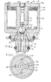
- the solenoid valve embodying the invention comprises a housing 10 that includes a transverse wall 11 having an axial extension 12 and an integral peripheral wall 13.
- the valve further includes a pole member 14 having an axial pole 15 and a transverse wall 16 extending to the peripheral wall 13 and connected thereto preferably by bending the edge 17a of the wall 13 over the periphery of the wall 16.
- transverse wall 16 would be connected to peripheral wall 13 by welding at edge 17.
- Pole 15 is provided with an axial opening 17 and a first conical valve seat 18 at its lower end.
- the end of pole 15 is tapered.
- the axial extension 12 is provided with an opening 19 into which an insert 20 is installed and secured in position by a suitable means such as press fit, welding or pinning. Opening 19 extends thru transverse wall 11.
- Insert 20 has an axial opening 34 and defines a second conical valve seat 21 at one end.
- a ball 22 is interposed between the seats 18, 21 and has limited movement.
- Axial grooves 23 in wall 11 and extension 12 adjacent seat 21 facilitate flow about the ball 22.
- Spring means in the form of a compression spring 24 and a member 25 are interposed in the opening between an apertured press fitted and welded pin 26 and a narrow portion of the opening to yieldingly urge the ball toward the second seat 21.
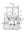
- the housing 10 and pole member 15 defines an annular cavity 27 in which a coil assembly including a coil holder 28 and an annular coil 29 are positioned. As shown the major portion of the ball 22 lies within the transverse wall 11 of the housing.
- O-rings 30, 31 are provided about the extension 12 so that the valve can be inserted in the appropriate place in the device such as a transmission with which it is used.
- a plurality of circumferentially spaced passages 33 are provided in housing 10 and extend from adjacent the periphery of the ball 22 through the axial extension of the housing at an acute angle to the axial inlet opening 34 in the axial extension to the periphery of the housing axially between O-rings 30, 31.
- the spring 24 urges the ball 22 against the second seat 21 so there will be no flow from the inlet 34 through the passages 33. However, there will be free communication between the passages 33, grooves 23 about the ball 22 past first seat 18 and through the passage 17 and opening 20a to the exterior which is normally connected to a sump or drain.
- the coil is energized, the ball 23 is drawn upwardly as viewed in FIG. 1 against the first seat 18 so that fluic can flow from the inlet 34 past the ball 22 and second seat 21 and through the passages 33 to the exterior. Fluid is prevented from flowing out of the opening 17 by seating the ball 22 against the seat 18.
- the flux induced by the coil 29 will follow a path through the center pole 15 into flange 16, through wall section 13 and end face 11, across the air gap between the ball 22 and bore 34, through ball 22, across the air gap between the ball 22 and center pole 15, and into the center pole 15. It should be noted that the seat 21 and, in this case, the entire insert 20 is non-magnetic and thus carries no applicable magnetic flux.
- Materials for the flux carrying components are normally low carbon mild steels or sintered irons while the non-magnetic seat material is normally an austenitic stainless steel for durability but could be any non-magnetic material.
- a clearance of 0,076 to 0,254 mm preferably is maintained between the ball 22 and opening 19 to minimize the air gap between them so as to optimize the magnetic circuit to minimize power requirements. Since the clearance is so small, the grooves 23 are necessary to allow the fluid to flow around the ball and out the exhaust port without undue restriction, and to minimize the hydraulic forces acting on the ball.
- the clearance between ball 22, when it engages one seat, and the other seat ranges between 0,076 to 0,508 mm.
- the lead wires from the coil pass through the end flange and are then attached to a standard quick connector that also receives the wires from the microprocessor.
- controlled output pressure is obtained through modulation of the "on" to "off” time during each cycle at any given frequency.
- the valves have been used at operational frequencies of from 30 to 100 hertz but higher or lower frequencies could be used.
- the operating frequency is normally constant with the amount of "on” time being varied within the cycle to give the proper output pressure. Theoretically, the output pressure would be zero, when the valve is “off”, and would be input pressure, when the valve is "on”; however, due to friction, inertia and elasticity in the hydraulic circuit, the output pressure tends to effectively average somewhere between zero and input depending on the ratio of "on” to "off” time.
- the coil is energized at a frequency of 100 hertz (cycles per second) which allows 10 ms of operation time for each cycle.
- the outlet pressure is varied by maintaining the duration of the energizing signal within the 10 ms time frame. The longer the signal is applied, the closer the average outlet pressure is to the inlet pressure.
- the ratio of pressure out to pressure in is a straight line function of the ratio of energized time to available cycle time, that is, at an "on" time of 3 ms (or 30% of 10 ms available), the output pressure would be 30% of the input pressure. In actual practice, it takes about approximately 1.6 ms of on time to unseat the ball.
- This lag is due to the time required to build sufficient magnetic force to overcome the spring force and ball inertia; likewise, it takes approximately 1.5 ms for the ball to return to the normally closed position once the coil current is shut off.
- This device is able to accurately regulate oil output pressure at 20%-l00% of input pressure.
- valve shown is particularly designed for use in a pulse width modulated mode, it can also be utilized in an on-off or steady state directional mode.
- the valve is shown as mounted in a typical transmission manifold 35 having an inlet manifold passage 36 and outlet channel 37, 38 that direct fluid from the valve to clutches or spool valves as the case may be. It can be seen that by providing a plurality of passageways 33 in the housing 11 at an acute angle to axial opening 34, the axial opening 34 can be made larger in diameter than when the outlet passages are formed in the insert 20 and are parallel to the axial opening 34 thereby limiting the diameter of the axial opening. As a result it is possible to obtain a greater volume of flow at the desired pressure.
Landscapes
- Engineering & Computer Science (AREA)
- General Engineering & Computer Science (AREA)
- Mechanical Engineering (AREA)
- Magnetically Actuated Valves (AREA)
- Multiple-Way Valves (AREA)
- Control Of Transmission Device (AREA)
Applications Claiming Priority (2)
| Application Number | Priority Date | Filing Date | Title |
|---|---|---|---|
| US06/629,955 US4570904A (en) | 1984-07-11 | 1984-07-11 | Solenoid valve |
| US629955 | 1984-07-11 |
Publications (3)
| Publication Number | Publication Date |
|---|---|
| EP0167933A2 true EP0167933A2 (de) | 1986-01-15 |
| EP0167933A3 EP0167933A3 (en) | 1986-10-08 |
| EP0167933B1 EP0167933B1 (de) | 1989-01-11 |
Family
ID=24525161
Family Applications (1)
| Application Number | Title | Priority Date | Filing Date |
|---|---|---|---|
| EP85107930A Expired EP0167933B1 (de) | 1984-07-11 | 1985-06-26 | Magnetventil |
Country Status (11)
| Country | Link |
|---|---|
| US (1) | US4570904A (de) |
| EP (1) | EP0167933B1 (de) |
| JP (1) | JPS6141090A (de) |
| KR (1) | KR890000075B1 (de) |
| AU (1) | AU577385B2 (de) |
| BE (1) | BE902833A (de) |
| BR (1) | BR8503132A (de) |
| CA (1) | CA1269021A (de) |
| DE (1) | DE3567520D1 (de) |
| IN (1) | IN162905B (de) |
| MX (1) | MX158534A (de) |
Cited By (3)
| Publication number | Priority date | Publication date | Assignee | Title |
|---|---|---|---|---|
| WO2008037553A1 (de) * | 2006-09-25 | 2008-04-03 | Robert Bosch Gmbh | Hydraulikblock |
| CN105202251A (zh) * | 2015-10-23 | 2015-12-30 | 宁波星宇国均汽车电磁阀有限公司 | 一种两位三通开关电磁阀 |
| DE102019209663A1 (de) * | 2019-07-02 | 2021-01-07 | Continental Teves Ag & Co. Ohg | Kugelschaltventil |
Families Citing this family (24)
| Publication number | Priority date | Publication date | Assignee | Title |
|---|---|---|---|---|
| US4674536A (en) * | 1986-04-25 | 1987-06-23 | Sealed Power Corporation | Electrohydraulic valves for use in a system |
| JPS6313976A (ja) * | 1986-07-05 | 1988-01-21 | Daihatsu Motor Co Ltd | 電磁弁 |
| US4741365A (en) * | 1986-08-04 | 1988-05-03 | Mcdonnell Douglas Corporation | Compound pneumatic valve |
| US4863142A (en) * | 1988-04-29 | 1989-09-05 | Sealed Power Corporation | Electromagnetic solenoid valve with variable force motor |
| US5000421A (en) * | 1988-04-29 | 1991-03-19 | Spx Corporation | Electromagnetic solenoid valve with variable force motor |
| US5018431A (en) * | 1988-12-09 | 1991-05-28 | Quadrastat Corporation | Apparatus for positioning a work implement |
| DE3922155C2 (de) * | 1989-07-06 | 1999-08-26 | Mannesmann Sachs Ag | Magnetventil |
| US5051631A (en) * | 1990-07-16 | 1991-09-24 | Spx Corporation | Electromagnetic solenoid valve with variable force motor |
| US5322260A (en) * | 1993-05-24 | 1994-06-21 | Borg-Warner Automotive, Inc. | Solenoid valve |
| US5326070A (en) * | 1993-05-24 | 1994-07-05 | Borg-Warner Automotive, Inc. | Solenoid valve |
| WO1995012543A1 (en) * | 1993-11-04 | 1995-05-11 | Geoffrey Miles Furness | Gas pressurized liquid delivery system |
| JPH09506743A (ja) * | 1993-12-15 | 1997-06-30 | ユナイテッド テクノロジーズ オートモーティブ,インコーポレイテッド | ソレノイド |
| US6102364A (en) * | 1997-07-30 | 2000-08-15 | Siemens Canada Limited | Control accuracy of a pulse-operated electromechanical device |
| US5950984A (en) * | 1997-11-03 | 1999-09-14 | Spx Corporation | Solenoid valve |
| US6276663B1 (en) | 2000-04-25 | 2001-08-21 | Acutex, Inc. | Normally rising variable force solenoid |
| DE10162502A1 (de) * | 2001-12-19 | 2003-07-03 | Bsh Bosch Siemens Hausgeraete | Mehrwegeventil und Kältemaschine mit Mehrwegeventil |
| US7195226B2 (en) * | 2004-08-27 | 2007-03-27 | Kelsey-Hayes Company | Solenoid valve with spherical armature |
| US7537145B2 (en) | 2007-02-01 | 2009-05-26 | Black & Decker Inc. | Multistage solenoid fastening device |
| DE102008028564A1 (de) * | 2007-07-03 | 2009-01-08 | Luk Lamellen Und Kupplungsbau Beteiligungs Kg | Hydrauliksystem zum Erzeugen eines Vorsteuerdruckes zum Ansteuern einer Getriebekomponente |
| US8347534B2 (en) * | 2007-07-09 | 2013-01-08 | Ruiz Iraldo F | Recirculating levitated beads fountain display apparatus |
| DE102009006445B3 (de) * | 2009-01-28 | 2010-07-15 | Hydac Fluidtechnik Gmbh | Proportional-Druckregelventil |
| RU2543365C2 (ru) * | 2009-06-03 | 2015-02-27 | Итон Корпорейшн | Гидравлическое устройство с магнитными фиксирующими клапанами |
| CN112547329A (zh) | 2020-11-23 | 2021-03-26 | 石家庄禾柏生物技术股份有限公司 | 一种试剂盒出液装置 |
| CN113685579B (zh) * | 2021-07-14 | 2023-12-05 | 中国航发贵州红林航空动力控制科技有限公司 | 一种两位三通常闭式压力比例阀 |
Family Cites Families (11)
| Publication number | Priority date | Publication date | Assignee | Title |
|---|---|---|---|---|
| DE2160264A1 (de) * | 1971-12-04 | 1973-06-07 | Weinzierl Hydraulik Kg | Hydraulikventil |
| GB1414301A (en) * | 1972-01-14 | 1975-11-19 | Ass Eng Ltd | Fluid control valves |
| FR2178464A5 (de) * | 1972-03-31 | 1973-11-09 | Peugeot & Renault | |
| DE2337886A1 (de) * | 1973-07-26 | 1975-02-06 | Daimler Benz Ag | Elektromagnetisches druckregelventil mit als verschlusskoerper dienendem kugelanker |
| ES480450A1 (es) * | 1978-07-12 | 1979-12-16 | Lucas Industries Ltd | Valvula de control de fluidos accionable electromagneticamente. |
| FR2439346A1 (fr) * | 1978-10-16 | 1980-05-16 | Renault | Electro-distributeur hydraulique a trois voies |
| DE7929196U1 (de) * | 1978-10-16 | 1980-01-17 | (Frankreich) | Elektromagnetisches Verteilerventil mit drei Wegen für hydraulische Flüssigkeiten |
| DE2948874A1 (de) * | 1979-12-05 | 1981-06-11 | Robert Bosch Gmbh, 7000 Stuttgart | Elektromagnetisch betaetigbares ventil |
| JPS5779278U (de) * | 1980-10-31 | 1982-05-15 | ||
| DE8215342U1 (de) * | 1982-05-26 | 1984-04-12 | Bosch-Siemens Hausgeräte GmbH, 7000 Stuttgart | Magnetventil |
| JPS60175884A (ja) * | 1984-02-07 | 1985-09-10 | シ−ルド・パワ−・コ−ポレ−シヨン | ソレノイドバルブ |
-
1984
- 1984-07-11 US US06/629,955 patent/US4570904A/en not_active Expired - Lifetime
-
1985
- 1985-06-06 AU AU43376/85A patent/AU577385B2/en not_active Ceased
- 1985-06-06 CA CA000483319A patent/CA1269021A/en not_active Expired - Lifetime
- 1985-06-17 IN IN452/CAL/85A patent/IN162905B/en unknown
- 1985-06-21 MX MX205742A patent/MX158534A/es unknown
- 1985-06-24 KR KR1019850004475A patent/KR890000075B1/ko not_active Expired
- 1985-06-26 EP EP85107930A patent/EP0167933B1/de not_active Expired
- 1985-06-26 DE DE8585107930T patent/DE3567520D1/de not_active Expired
- 1985-06-28 BR BR8503132A patent/BR8503132A/pt not_active IP Right Cessation
- 1985-07-01 JP JP14442485A patent/JPS6141090A/ja active Granted
- 1985-07-08 BE BE0/215311A patent/BE902833A/fr not_active IP Right Cessation
Cited By (5)
| Publication number | Priority date | Publication date | Assignee | Title |
|---|---|---|---|---|
| WO2008037553A1 (de) * | 2006-09-25 | 2008-04-03 | Robert Bosch Gmbh | Hydraulikblock |
| CN101517291B (zh) * | 2006-09-25 | 2011-05-18 | 罗伯特.博世有限公司 | 液压块 |
| US8205634B2 (en) | 2006-09-25 | 2012-06-26 | Robert Bosch Gmbh | Hydraulic block |
| CN105202251A (zh) * | 2015-10-23 | 2015-12-30 | 宁波星宇国均汽车电磁阀有限公司 | 一种两位三通开关电磁阀 |
| DE102019209663A1 (de) * | 2019-07-02 | 2021-01-07 | Continental Teves Ag & Co. Ohg | Kugelschaltventil |
Also Published As
| Publication number | Publication date |
|---|---|
| EP0167933B1 (de) | 1989-01-11 |
| US4570904A (en) | 1986-02-18 |
| JPH0343511B2 (de) | 1991-07-02 |
| CA1269021A (en) | 1990-05-15 |
| BR8503132A (pt) | 1986-03-18 |
| AU577385B2 (en) | 1988-09-22 |
| BE902833A (fr) | 1985-11-04 |
| JPS6141090A (ja) | 1986-02-27 |
| KR860001308A (ko) | 1986-02-24 |
| MX158534A (es) | 1989-02-09 |
| DE3567520D1 (en) | 1989-02-16 |
| EP0167933A3 (en) | 1986-10-08 |
| KR890000075B1 (ko) | 1989-03-07 |
| AU4337685A (en) | 1986-01-16 |
| IN162905B (de) | 1988-07-23 |
Similar Documents
| Publication | Publication Date | Title |
|---|---|---|
| EP0167933A2 (de) | Magnetventil | |
| US4595035A (en) | Solenoid valve | |
| US4556085A (en) | Solenoid valve | |
| EP2916055B1 (de) | Elektromagnetisch betätigtes Durchflusssteuerventil | |
| US5218996A (en) | Three-way three-position solenoid valve | |
| US4979542A (en) | Pulse modulated hydraulic valve | |
| EP0919754B1 (de) | Elektromagnetisches Proportionalventil mit Ankerdämpfung | |
| US4610428A (en) | Hermetically sealed electromagnetic solenoid valve | |
| CA1252689A (en) | Closed loop type proportional electromagnetic valve for hydraulic control | |
| EP0762025B1 (de) | Elektrisch betätigtes Regelventil | |
| US5322260A (en) | Solenoid valve | |
| US20050098211A1 (en) | Three-way bleed type proportional electromagnetic valve | |
| US6792975B2 (en) | Pulse-width modulated solenoid valve including axial stop spool valve | |
| EP1790889A1 (de) | Ventilsteuerung | |
| JPH04244682A (ja) | 電磁式の弁 | |
| EP0160120B1 (de) | Elektromagnetisch betätigbares Ventil | |
| EP0385286B1 (de) | Mittels eines eine veränderliche Kraft erzeugenden Elektromagneten arbeitender Druckregler für die elektronische Steuerung eines Getriebes | |
| EP0628460A1 (de) | Umschaltventil und damit ausgerüstetes Durchflussregelventil | |
| EP1209327A2 (de) | Hydraulisch dämpfendes, reibungsarmes Elektromagnetventil | |
| JP3014534B2 (ja) | ソレノイドバルブ | |
| EP0908654B1 (de) | Durchflussregelndes Magnetventil | |
| JPH0289881A (ja) | 圧力制御電磁弁 |
Legal Events
| Date | Code | Title | Description |
|---|---|---|---|
| PUAI | Public reference made under article 153(3) epc to a published international application that has entered the european phase |
Free format text: ORIGINAL CODE: 0009012 |
|
| AK | Designated contracting states |
Designated state(s): DE FR GB IT |
|
| PUAL | Search report despatched |
Free format text: ORIGINAL CODE: 0009013 |
|
| AK | Designated contracting states |
Kind code of ref document: A3 Designated state(s): DE FR GB IT |
|
| 17P | Request for examination filed |
Effective date: 19861129 |
|
| 17Q | First examination report despatched |
Effective date: 19871022 |
|
| ITF | It: translation for a ep patent filed | ||
| GRAA | (expected) grant |
Free format text: ORIGINAL CODE: 0009210 |
|
| AK | Designated contracting states |
Kind code of ref document: B1 Designated state(s): DE FR GB IT |
|
| REF | Corresponds to: |
Ref document number: 3567520 Country of ref document: DE Date of ref document: 19890216 |
|
| ET | Fr: translation filed | ||
| PLBE | No opposition filed within time limit |
Free format text: ORIGINAL CODE: 0009261 |
|
| STAA | Information on the status of an ep patent application or granted ep patent |
Free format text: STATUS: NO OPPOSITION FILED WITHIN TIME LIMIT |
|
| 26N | No opposition filed | ||
| ITTA | It: last paid annual fee | ||
| REG | Reference to a national code |
Ref country code: GB Ref legal event code: 732E |
|
| REG | Reference to a national code |
Ref country code: FR Ref legal event code: TP Ref country code: FR Ref legal event code: CD |
|
| REG | Reference to a national code |
Ref country code: GB Ref legal event code: IF02 |
|
| PGFP | Annual fee paid to national office [announced via postgrant information from national office to epo] |
Ref country code: FR Payment date: 20020530 Year of fee payment: 18 |
|
| PGFP | Annual fee paid to national office [announced via postgrant information from national office to epo] |
Ref country code: GB Payment date: 20020619 Year of fee payment: 18 |
|
| PGFP | Annual fee paid to national office [announced via postgrant information from national office to epo] |
Ref country code: DE Payment date: 20020620 Year of fee payment: 18 |
|
| PG25 | Lapsed in a contracting state [announced via postgrant information from national office to epo] |
Ref country code: GB Free format text: LAPSE BECAUSE OF NON-PAYMENT OF DUE FEES Effective date: 20030626 |
|
| PG25 | Lapsed in a contracting state [announced via postgrant information from national office to epo] |
Ref country code: DE Free format text: LAPSE BECAUSE OF NON-PAYMENT OF DUE FEES Effective date: 20040101 |
|
| GBPC | Gb: european patent ceased through non-payment of renewal fee |
Effective date: 20030626 |
|
| PG25 | Lapsed in a contracting state [announced via postgrant information from national office to epo] |
Ref country code: FR Free format text: LAPSE BECAUSE OF NON-PAYMENT OF DUE FEES Effective date: 20040227 |
|
| REG | Reference to a national code |
Ref country code: FR Ref legal event code: ST |