EP0167910B1 - Optisches Signalaufzeichnungsgerät mit zwei Lasern - Google Patents
Optisches Signalaufzeichnungsgerät mit zwei Lasern Download PDFInfo
- Publication number
- EP0167910B1 EP0167910B1 EP85107744A EP85107744A EP0167910B1 EP 0167910 B1 EP0167910 B1 EP 0167910B1 EP 85107744 A EP85107744 A EP 85107744A EP 85107744 A EP85107744 A EP 85107744A EP 0167910 B1 EP0167910 B1 EP 0167910B1
- Authority
- EP
- European Patent Office
- Prior art keywords
- optical
- beams
- laser
- disk
- light
- Prior art date
- Legal status (The legal status is an assumption and is not a legal conclusion. Google has not performed a legal analysis and makes no representation as to the accuracy of the status listed.)
- Expired - Lifetime
Links
Images


Classifications
-
- G—PHYSICS
- G11—INFORMATION STORAGE
- G11B—INFORMATION STORAGE BASED ON RELATIVE MOVEMENT BETWEEN RECORD CARRIER AND TRANSDUCER
- G11B7/00—Recording or reproducing by optical means, e.g. recording using a thermal beam of optical radiation by modifying optical properties or the physical structure, reproducing using an optical beam at lower power by sensing optical properties; Record carriers therefor
- G11B7/12—Heads, e.g. forming of the optical beam spot or modulation of the optical beam
- G11B7/125—Optical beam sources therefor, e.g. laser control circuitry specially adapted for optical storage devices; Modulators, e.g. means for controlling the size or intensity of optical spots or optical traces
-
- G—PHYSICS
- G11—INFORMATION STORAGE
- G11B—INFORMATION STORAGE BASED ON RELATIVE MOVEMENT BETWEEN RECORD CARRIER AND TRANSDUCER
- G11B7/00—Recording or reproducing by optical means, e.g. recording using a thermal beam of optical radiation by modifying optical properties or the physical structure, reproducing using an optical beam at lower power by sensing optical properties; Record carriers therefor
- G11B7/004—Recording, reproducing or erasing methods; Read, write or erase circuits therefor
- G11B7/0045—Recording
- G11B7/00458—Verification, i.e. checking data during or after recording
-
- G—PHYSICS
- G11—INFORMATION STORAGE
- G11B—INFORMATION STORAGE BASED ON RELATIVE MOVEMENT BETWEEN RECORD CARRIER AND TRANSDUCER
- G11B7/00—Recording or reproducing by optical means, e.g. recording using a thermal beam of optical radiation by modifying optical properties or the physical structure, reproducing using an optical beam at lower power by sensing optical properties; Record carriers therefor
- G11B7/12—Heads, e.g. forming of the optical beam spot or modulation of the optical beam
- G11B7/123—Integrated head arrangements, e.g. with source and detectors mounted on the same substrate
Definitions
- the present invention relates to optical signal recorders, particularly of the disk type, and to optical data recorders which according to the present invention can be a compact unit with a lightweight optical head movable with respect to an optical record medium.
- Optical data recorders have been noted for their high areal recording density.
- One of the drawbacks of many of the optical data recorders is the inability to instantaneously verify that signals being recorded have been, in fact, recorded. Verification of such recording is referred to as "direct-read-after-write" (DRAW).
- DRAW direct-read-after-write
- Such DRAW requires that two light beams simultaneously impinge on the optical record medium in a predetermined spaced-apart relationship.
- a first light beam that records the signals onto the record medium is a high power, or high intensity, beam which alters the optical properties of the recording surface.
- a second reading or sensing beam In immediate trailing juxtaposition to the recording beam for scanning the recording created by the recording beam just after it is recorded.
- the physical separation on the record member along a track being recorded by the recording beam is in the order of 20-60 microns.
- Any optical signal recorder that is to provide the DRAW capability requires the efficient generation of these two beams for simultaneously recording and readback of signals being recorded and then the separation of the light reflected from the record member of both beams.
- Other applications of multi-beam heads include erase-before- write (rewriteable media) and a three-beam head for erase-before-write then read-after-write.
- U. S. Patent 4,100,577 shows a single-laser (gaseous type), two-beam system providing the DRAW function. While the function is performed, the number of optical elements and the character of those optical elements work against providing an extremely compact optical signal recorder. Note the two extended light paths required in the beam splitting operation. Rather than provide a single laser, which requires an extremely high-power laser for providing both recording energy and sensing energy; two-laser systems have been employed. A two-laser system is attractive, particularly when semiconductive lasers are used.
- One widely-known prior art technique is to cross-polarize the read and write beams. This arrangement has proven not to be satisfactory because of the known problems of beam separation of the light reflected from the record member by the read and write beams.
- U. S. Patent 4,085,423 shows a two-laser system.
- One of the lasers operates at a high power, which is reflected by a dichroic mirror. That laser beam is also provided for tracking and data sensing.
- a second laser source of low power and of different frequency projects its beam through the dichroic mirror such that its beam is reflected to a focus-controlling photodctector.
- Other configurations of two laser-two frequency optical signal recorders are known. When the lasers have widely different frequencies, the thermal characteristics and focus control of the lasers becomes complicated adding to the weight and space required for implementing such a signal recorder.
- Patent 4,225,873 shows two gas lasers, which are extremely large and mounted on a frame rather than on a head arm which is movably across the face of an optical record disk. Because of the size of the components, including a Glan prism, mirrors and several other components, this system requires not only two lasers having different frequencies of operation which emit light having different wavelength, but results in a relatively large signal recorder.
- the Glaan prism employs refractive and reflective techniques, such as described in analytical form by Hect & Zajak in their book "Optics” published by Addison Wellsley, 1974, pp. 72-84.
- This publication defines the mathematics of optical refraction and internal reflection and tends to explain the operation of a Glan prism.
- This publication is incorporated by reference for defining the theory of operation of the present invention. Additional refractive optical signal processing is shown in the USSR Patent 289465, where in two optical members are separated by an air slot for providing an optical attenuator.
- a refractive optical beam combiner is shown in U. S. Patent 3,743,383.
- This combiner is designed for high power laser beams, apparently, much more powerful than desired for optical signal recorders. It appears that these optical components and their spacing, operate because the input signals have different wave-lengths. As mentioned earlier, it is desired to have both lasers, if possible, operate at the same frequency. The temperature characteristics of identical lasers tend to prevent differential focus errors between the write and read beams, such that a single focus control is easily applicable to both the reading and recording. If both lasers can electrically and optically track in a similar fashion with respect to temperature changes, then the optical signal recorder may exhibit a wider range of tolerance to temperature variations, as well as exhibiting a greater degree of stability of operation during turn on and subsequent operations.
- Another aspect of providing a compact optical signal recorder is to reduce the amount of electronics involved in processing the optical signals. By reducing the electronics and taking advantage of large scale integration, electronics can be conveniently mounted on the head arm along with the optical elements.
- US Patent 4,059,841 shows a single photodetector system that responds to the reflected light beams found in the optical signal record member to provide not only data information, but also focus and tracking information. In many instances, two photodetectors are employed - one for providing tracking, and a second one for providing focus and data detection. With efficient semiconductive photodetectors, either one or two photodetectors can be employed for providing a compact optical signal recorder.
- DE-A-3300581 which is reflected in the prior art portion of claim 1 relates to an optical information recording/reproducing apparatus where a first light beam is refracted through an inclined multi-layered surface of a prism and a second beam is reflected by the surface.
- the angular difference between the two output beams from the prism is defined by the composition of the multi-layered film on the surface.
- GB-A-2097150 discloses a recording on reading apparatus for optical record carriers where two laser housings are arranged within a small distance in order to reduce thermal instability.
- an optical signal recorder uses multiple lasers of the same frequency with a minimum of optical components for minimising optical path lengths and yet provide a recording beam of high power and a read beam of low power.
- the present invention provides an optical signal recorder having an optical disk support for relatively moving an optical disk with respect to optical transducer means movably supported with respect to the optical record disk, said optical transducer means, including the combination of: first and second laser means for operating at substantially the same frequency and for emitting first and second light beams respectively having similar wavelengths respectively for reading and recording signals from and to the optical record disk; a beam combiner optically coupled to both said laser means for receiving both said emitted light beams and for combining same into a single light path, but in a diverging relationship to each other at a predetermined angle less than about one degree; an optical means optically coupled to said beam combiner for receiving the diverging combined light beams and for transferring same to said optical record disk for respectively reading and recording signals from and on said optical record disk caused by at least one of said combined emitted light beams; and detector means in said optical means for detecting the reflected light as received by said optical means to indicate its contained informational content; said beam combiner including a first surface for reflecting the light beam from said second laser
- two identical lasers on a common highly thermally conductive element emit their beams into the beam combiner and thence the beams are projected in a slightly diverging relationship to a record member for enabling recording and read-after-write.
- Polarisation optics are interposed between the combiner and the optical disks for separating a reflected read beam for enabling data detection including direct-read-after-write verification, focus detection, and tracking control.
- the beam combiner, beam splitter and polarisation optics are a composite but unitary member having a major light path axis parallel to the disk.
- a mirror optically couples the composite member through a focusing element allowing a path orthogonal to the major axis of the composite member.
- a detector system is mounted immediately adjacent the focuser and intermediate the major optical axis of the optical composite for minimizing the axial depth of the optics with respect to the axis of rotation of the disk.
- Integrated circuits are mounted on the head arm adjacent the detector, preferably intermediate the optical composite and the disk for making a compact optical signal recorder.
- the lasers are preferably mounted remote from the focuser and emit light beams parallel to the planar extent of the disk.
- the beam combiner is preferably a refraction-internal-reflection type, wherein the read beam from a first laser is optically directed using optical properties of the beam combiner such that it can be used as a sensing beam.
- a beam from a second laser, which is to be a recording, or write, laser is internally reflected with insignificant attenuation.
- the arrangement in the beam combiner allows a path carrying a read beam and a write beam at a slightly diverging relationship, such as one-half degree.
- the write beam precedes the read beam on an optical record member for enabling direct-read-after-write verification.
- an optical wedge is disposed in a slightly-spaced relationship from the surface of the beam combiner used to refract the read beam and internally reflect the write beam.
- the write beam has two internal reflections for making a more compact optical apparatus.
- Figure 1 is a simplified side-elevationed view of an optical head disposed adjacent to an optical record disk.
- Figure 2 is a combined diagrammatic and plan view of the Figure 1 illustrated apparatus with the head arm being viewed along a plane intermediate the Figure 1 record disk and the illustrated head arm assembly.
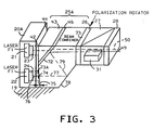
- Figure 3 diagrammatically illustrates a preferred optical composite member for use in the Figure 1 illustrated apparatus for achieving a compact optical signal recorder.
- Figures 1 and 2 illustrate a first embodiment
- Figure 3 illustrates a portion of a preferred, or second, embodiment.
- the optical signal recorder generally denominated by numeral 10
- Optical disk 13 is mounted for rotation on a suitable spindle, which is controlled in accordance with using known techniques as represented by numeral 12.
- spindle speed control can either be a constant angular speed or an angular speed that varies with the radial position of the head arm 17 mounted for radial translation with respect to the record disk 13 in the usual manner.
- Information processing and control circuits 14 are connected to a host processor, communication line or other utilization device as indicated by the double-headed outline arrow 14A.
- the electrical connections of signal circuits 14 to various circuitry in the recorder are indicated by the plurality of lines 14B.
- Included in signal recorder 10 are the usual tracking circuits 15 and focusing control circuits 16.
- Circuits 14, 15 and 16 employ electrical signals derived from a detector, later described, for analyzing the informational content of the reflected light beams for providing optical signal data functions based upon the informational content contained on a recording coating (not shown) of the optical record disk 13.
- data can be recorded as a series of holes, series of reflective and nonreflective areas, a series of bumps, which tend to scatter the impinging light with intermingled planar areas which tend to reflect the light, and the like. All of the informational content is arranged in a series of concentric tracks or a single spiral track on the coating surface of the optical record disk, as is well-known.
- the function of tracking circuits 15 is to ensure that head arm 17 precisely positions the optical head over a record track being scanned.
- Focus circuits 16 detect the focus of a light beam to maintain good focus at the recording surface of the optical record disk 13. In Figure 1, the recording surface is represented by the lower surface of the disk 13.
- the optical head assembly employing the present invention is mounted on frame 19, which in turn is suitably mounted in head arm 17.
- frame 19 is a highly thermal conductive portion 20, which suitably thermally connects first laser 21 and second laser 22.
- the first and second lasers are of the semiconductive type preferably operating at the same frequency for emitting identical wavelength light beams, the first laser 21 emitted light beam for sensing information recorded on disk 13, while the laser 22 emitted light beam is modulated for recording information on optical record disk 13.
- the optics of the invention attenuate the energy of the first laser 21 emitted light beam such that it is suitable for reading; the power output of the first laser 21 power output is also adjustable to achieve suitable read beam power levels.
- the two lasers being thermally connected together tend to operate at the same temperature and therefore tend to emit light beams that vary identically with temperature changes occurring during operation of the optical signal recorder 10. This feature adds stability to the operation of the recorder.
- the lasers 21 and 22 supply their light beams, respectively, through collimating optics 23 and 24.
- a beam combiner 25 receives the beams from lasers 21 and 22 and supplies the combined beams, as later detailed, to half-wave plate 26.
- plate 26 is desired only for making the assembly more compact for facilitating optical efficiencies of the assembly.
- the effect of the half-wave plate is to rotate the polarization of both beams 41, 50 simultaneously. This rotation enables beam splitter to be oriented for positioning detector 31 as shown in Figure 1--between the disk 13 and splitter 27--for minimizing the size of the optical assembly, as will become apparent.
- Half-wave plate 26 is suitable bonded to combiner 25.
- polarization-sensitive beam splitter 27 of usual construction.
- Beam splitter 27 is suitably bonded to the half-wave plate 26.
- Mounted on the output face of beam splitter 27 is one-quarter wave length polarization plate 28 which retards the polarization of both beams by 45 degrees, as is well- known.
- the light reflected from record member 13 is further rotated 45 degrees, such that the beam splitter rather than transmitting the light back to the splitter into the lasers, reflects the disk 13 reflected light to detector 31, which is disposed on frame 19 intermediate the major optical axis of elements 25, 26, 27 and 28, and record disk 13.
- Quarter-wave plate 28 is suitably bonded to splitter 27 for making a composite optical assembly consisting of combiner 25, half-wave plate 26, splitter 27 and quarter-wave plate 28.
- mirror assembly 29 which includes planar pivotally mounted mirror 29M which directs the diverging beams through focus element 30, an objective lens system, onto the recording surface of optical record disk 13.
- Mirror system 29 may be made responsive to tracking circuits 15 for providing tracking functions of the diverging beams with respect to the track defined on optical record disk 13.
- focus unit 30 may flexibly mount its objective lens (not shown) to provide the tracking function using known tracking apparatus employed in combination with such focusing elements.
- frame 19 provides support for a compact optical system having a simple optical path and that all of the elements mounted on the frame are in close proximity for minimizing the size of frame 19 and head arm 17.
- Electrical integrated circuits may be mounted on frame 19 adjacent to detector 31.
- a first optical element (amorphous glass or plastic, for example) 35 of beam combiner 25 includes a first angled surface 36.
- Surface 36 in a preferred embodiment provides an air-to-optical element interface which refracts the read beam 42 emitted from laser 21 and internally reflects the emitted write beam 40 received from laser 22.
- Beam 40 enters optical element 35 through input surface 37, which is disposed substantially orthogonal with respect to output surface 38.
- substantially orthogonal means that the angle between beam 40 and surface 37 is near ninety degrees; the angle differs from ninety degrees in the preferred embodiment by the small angle of divergence desired between the light beams 41 and 50, such as one-half of one degree.
- the angle of divergence between beams 41 and 50 can be obtained by changing the angle of surface 36 with respect to the output surface 38 rather than altering the angle between beam 40 and surface 37. For avoiding refraction, it is preferred that the angle between beam 40 and surface 37 be kept close to ninety degrees.
- Output surface 38 pauses the diverging read and write beams to be transmitted through halfwave plate 26 as beams 41 and 50, respectively.
- the angle of divergence between beams 41 and 50 for the illustrated embodiment is approximately one-half degree.
- Surface 36 in refracting read beam 42 reduces the beam energy content by approximately 25 percent; therefore the surface acts as an optical attenuator having internal reflection properties.
- the laser 21 emitted beam 42 has a predetermined cross-sectional shape, such as circular or slightly ellipsoid. When such a beam impinges upon an angled surface 36, because of the angle of incidence, the beam cross-sectional shape is distorted along one axis of the beam.
- input optical element 43 is disposed upon surface 36 and spaced therefrom a short distance. In the preferred embodiment, the spacing can vary from a few microns to about one-fourth of a millimeter. The spacing should be at least about one-tenth wavelength of the lasers 21, 22 for effecting internal reflectance. As the spacing increases, the size of the optical combiner 26 gets larger.
- annular ring 46 can be a metallic shim; while for a micron spacing, ring 46 may consist of a suitable coating of adhesive. Coating 46 preferably bonds input optical member 43 to optical element 35.
- the laser 21 emitted beam 42 passes through orthogonally disposed input surface 44 of the input optical member 43.
- the beam 42 is refracted by the glass-to-air surface 45 away from a line normal to surface 36.
- surfaces 36 and 45 be substantially planar and be disposed in a closely parallel relationship for maintaining the output beam 50 substantially parallel to input beam 42.
- the spacing is preferably small because the relatively large upward (Figure 2) refractive angle of the beam 42 at surface 45.
- the resultant diverging beams 41 and 50 which are still identically polarized in a preferred environment, then travel through beam splitter 27, then through quarter-wave plate 28, to be reflected to disk 13 by mirror 29M.
- the laser 22 emitted beam 41 is internally reflected at surface 36 as write beam 51 which goes via components 27 and 29 to optical disk 13.
- Read beam 50 goes through focus unit 30 as read beam 52 to optical record disk 13.
- the record disk 13 rotates into the plane of the drawing as viewed in Figure 1 and as represented by arrow 13R.
- Write beam 51 scans a track on disk 13 immediately ahead of read beam 52.
- the spacing of the beams 51 and 52 on record disk 13 is preferably between 20 and 50 microns, no limitation thereto intended.
- the read beam is shown as a heavy dashed line while the write beam is shown as a light dashed line. These lines represent the respective optical axes of the illustrated beams, it being understood that the optical components are designed to optically process most of the energy of the illustrated beams.
- write beam 51 is represented by an upper "X”
- read beam 52 is represented by an "X” below and spaced from the write beam 51.
- This view is looking into the focuser 30 from the disk 13.
- the relative motion of disk 13, as viewed in Figure 2 is toward the top of the figure.
- Optical record disk 13 reflects the beams 51 and 52, as is well-known, back along paths 51 and 52, respectively.
- Mirror 29M directs the reflected beams to polarization-sensitive beam splitter 27 after passing through quarter-wave plate 28 a second time.
- the polarization of the reflected beams are rotated ninety degrees with respect to the laser 21, 22 beams, respectively, beam splitter 27 then reflects both of the reflected beams toward detector 31, as beams 53 and 54, respectively, for the reflected write and read beams.
- the reflected write beam will have a greater intensity than the reflected read beam.
- a mask 56M disposed between detector 31 and lens 56, having an aperture 56A for passing reflected read beam 54 while blocking out reflected write beam 53.
- Lens 56 passes the reflected beams toward mask 56M and detector system 31.
- Detection system 31 can be of any known optical detector design. Alternatively, the lens and detector system can be sufficiently small such that it only receives reflected read beams; the divergence of beams 53 and 54 providing physical isolation.
- the lasers 21 and 22, being of the semiconductor type, can be modulated directly by signal circuits 14 using known techniques; in particular modulating write laser 22 provides information modulation in write beam 40.
- Read beam 21 can be of the constant intensity type or can be intensity modulated for provided additional tracking and focusing functions.
- Detector 31 provides a data output signal derived from reflected read beam 52 over line 57 to signal circuits 14. This means that the data detector, preferably a single integrated-circuit chip, is suitably mounted as a part of detector system 31. Tracking information, which can be derived by detector system 31 from either the reflected write or read beam, provides tracking error information signals over line 58 to tracking circuit 15. Tracking circuit 15 analyzes the tracking error signals and provides control signals over line 59 either to tracking mirror system 29 or to the focus unit 30, whichever does the tracking function. Detector system 31 also provides focus error signals over line 60 to focus circuit 16 which, in turn, provides focus error control signals over line 61 to focus unit 30. Operations of the tracking and focus circuits 15 and 16 are well-known and not described for that reason.
- the Figures 1 and 2 illustrated beam combiner 25 requires that lasers 21 and 22 be disposed to emit substantially orthogonal beams (the angle between the laser 21, 22 beams is ninety degrees plus or minus the angle of divergence of beams 41, 50).
- Figure 3 illustrates a preferred embodiment wherein the lasers 21 and 22 emit substantially parallel beams such that thermal conduction mount 20A is smaller, hence lighter and the losers are closer together. This means that the lasers 21 and 22 operate at a much closer temperature and therefore operate more consistently with temperature changes.
- Thermal conduction unit 20A is diagrammatically shown for illustrating the close proximity of the two lasers. Read laser 21 cooperates with the preferred beam combiner 25A as described with respect to Figures 1 and 2.
- the other elements of the optical composite are suitably bonded as described for Figures 1 and 2.
- the write or second laser 22 is mounted coplanar with laser 21 on thermal conduction mount 20A such that its emitted write or recording beam 76 is substantially parallel to the emitted read beam 42.
- the laser beams diverge at about the desired angle of divergence; such small divergence is defined as substanially parallel.
- beam combiner 25 includes a depending portion for changing the direction of the laser 22 beam 76.
- the input surface 74 of beam combiner 25A for the write beam 76 is also angled with respect to the input plane including input surface 44 of optical input element 43.
- this angle 75 is less than one degree for corresponding to the desired angle of divergence and for receiving the laser 22 emitted light beam orthogonally to its surface plane.
- input surface 74 slightly refracts the write beam 76 along optical axis 77 to internal reflective surface 78.
- the laser 22, already at a small angle of precise orthogonality, is not refracted by surface 74, but is already aligned with path 77.
- the refracted or internal beam 77 is internally reflected by surface 78 along optical axis 79 onto input-reflective surface 72, which corresponds to surface 36 shown in Figures 1 and 2.
- the output write beam diverges from the read beam 50 at an angle of less than one degree.
- operation of an optical head in the preferred embodiment is identical to that described for Figures 1 and 2.
- detector system 31 is mounted on the face of splitter 27 facing the viewer; mirror 29 is disposed to reflect the beams 49, 50 toward the viewer.
- surface 74 can be parallel to surface 73 requiring laser 22 be mounted at an angle thereto such that beam 76 is refracted to beam 77.
- Other geometric variations can also be employed.
- the optical members 35,43 of combiner 25 and optical members constituting combiner 25A consist of amorphous optical glass.
- Other optical amorphous materials such as plastic materials, can be readily substituted for the optical glass.
- Such materials are not birefringent; such as crystalline materials of many beam combiners.
- the index of refraction of the materials and the wavelength of the laser beams emitted by lasers 21,22 affect the angles required for constructing the described beam combiners.
- the indices of refraction of various materials are empirically determined in a usual manner.
- the indices of refraction of many commercially available optical materials are published by the various manufacturers.
- optical glass used in constructing one embodiment of the invention has an index of refraction of 1.511.
- the equations, particularly equation (4.63) on page 80, of the "Optics" article, supra, can be used to calculate the angles necessary for constructing a beam combiner using the present invention. Such calculations also lead to a desired spacing between surfaces 36 (or 72) and 45 as described earlier.
- the angle 75 of surface 74 with respect to the plane of output surface 73 will also vary with the above-described parameters and can be calculated as well using the teachings of the above-cited article.
- the calculations are simplified when all of the members of the combiner have the same index of refraction; such a selection is not required to practice the present invention. Also, when lasers 21,22 supply beams of light having the same wavelength, design and construction of the combiner 25,25A is simplified.
- spring-shaped spacer 46 consisted of deposited spacer, such as a metal or a glass.
- Norland 61 adhesive a commercially available adhesive, may be used to bond all of the optical components of the described optical composite.
- the approximate axis of beam 50 is deemed to be the major axis of the optical composite and is preferably disposed parallel to the plane of optical record disk 13 as best seen in Fig. 1. This arrangement tends to minimize the axial depth of the optical disk recorder 10. While it is not necessary for the beams to enter the combiner orthogonally to the various input surfaces, for desired power transfer and beam direction to obtain diverse angles of divergence in between beams 41, 50, this orthogonal relationship should be maintained.
- one embodiment of the beam combiner 25A surface 72 was disposed at 41 degrees, 15 minutes with respect to surface 73, surfaces 74 and 72 subtended an angle of about 137 degrees, 46 minutes and the gap between surfaces 72 and input optical wedge 43 was about 0.25 millimeters.
- the output surface 73 was parallel to input surface 44, the latter surface was orthogonal (to the axis of beam 42).
- Combiner 25A consisted of amorphous glass having an index of refraction of 1.511 and an objective lens and focal length of objective lens in focuser 30, such that an angle of divergence subtended by the axes of light beams 41 and 50 resulted in a separation of about 20 microns on the optical disk 13.
Claims (7)
- Optisches Signalaufzeichnungsgerät mit einer Halterung für eine optische Disk, um eine optische Disk (13) relativ bezüglich optischer Wandlermittel zu bewegen, welche bezüglich der optischen Aufzeichnungsdisk beweglich gelagert sind,
wobei die optischen Wandlermittel, die folgende Kombination enthalten:
erste und zweite Lasermittel (21, 22), die im wesentlichen mit derselben Frequenz betrieben werden und erste beziehungsweise zweite lichtstrahlen aussenden, welche mit ähnlichen Wellenlängen Signale von der optischen Aufnahmedisk (13) lesen beziehungsweise auf ihr aufzeichnen;
ein Strahlvereiner (25), der optisch mit beiden Lasermitteln (21, 22) gekoppelt ist, um beide ausgesandten Lichtstrahlen (40, 42) zu empfangen und um dieselben in einen einzigen Lichtweg zu vereinen, wobei sie jedoch, in einem vorbestimmten Winkel, der kleiner als etwa ein Grad ist, zueinander eine divergierende Beziehung aufweisen;
ein optisches Mittel (27, 29) das optisch mit dem Strahlvereiner (25) zum Empfangen der divergierenden vereinten Lichtstrahlen (41, 50) und zum Überführen derselben an die optische Aufzeichnungsdisk (13) gekoppelt ist, um, von zumindest einem der vereinten ausgesendeten Lichtstrahlen verursacht, Signale von der optischen Aufnahmedisk (13) zu lesen beziehungsweise auf ihr aufzuzeichnen, und
Detektormittel (31) in dem optischen Mittel zum Detektieren des reflektierten Lichtes, das von dem optischen Mittel empfangen wird, um dessen Informationsinhalt anzuzeigen,
wobei der Strahlvereiner (25) eine erste Oberfläche (36) zum Reflektieren des Lichtstrahles (40) vom zweiten Lasermittel (22) und eine zweite Oberfläche (45) in Abstand von der ersten Oberfläche (36) zum Brechen des Lichtstrahles (42) vom ersten Lasermittel (21) ungefähr an den Punkt der ersten Oberfläche (36), an dem der Lichtstrahl (40) des zweiten Lasermittels (22) reflektiert wird aufweist, wobei der Lichtstrahl (42) vom ersten Lasermittel (21) weiters durch die erste Oberfläche gebrochen wird, um dem einzigen Lichtweg zu folgen, sodaß er als Lesestrahl verwendet werden kann, wogegen der Lichtstrahl (40) vom zweiten Lasermittel (22) durch den Strahlvereiner (25) ohne wesentliche Ablenkung durchgeht, um als Schreibstrahl verwendet zu werden,
dadurch gekennzeichnet, daß
beide Lasermittel (21, 22) eng benachbart mit Mitteln (19) montiert sind, die einen hohen thermischen Leitfähigkeitsabschnitt (20) in einer thermischen Leitungsverbindung zu beiden Lasermitteln (21, 22) besitzen, sodaß beide Lasermittel (21, 22) im wesentlichen an derselben Temperatur arbeiten, und
die erste und zweite Oberfläche (36, 45) zueinander einen geringen Abstand aufweisen, sodaß die Lichtintensität des Lichtstrahles (42) vom ersten Lasermittel (21) durch interne Reflexion an der ersten Oberfläche (36) so weit verringert wird, daß er als Lesestrahl verwendet werden kann. - Optisches Signalaufzeichnungsgerät nach Anspruch 1, bei welchem das optische Mittel (27, 29) eine Eintrittsfläche (38) aufweist, die am Strahlvereiner (25) befestigt ist, um die ausgesandten Lichtstrahlen (40, 42) zu empfangen, und einen polarisationsempfindlichen Strahlteiler (27) mit einem auf den Strahlteiler (27) geklebten Lambda/4-Drehplättchen (28) enthält, das optisch zwischen dem Strahlteiler (27) und der optischen Aufzeichnungsdisk (13) angeordnet ist, wobei der Strahlteiler (27) eine polarisationsempfindliche Reflexionsebene aufweist, die unter 45° bezüglich eines der divergierenden ausgesandten Lichtstrahlen angeordnet ist, sodaß dieser eine divergierender Lichtstrahl, der von der optischen Disk reflektiert wird, vom Strahlteiler (27) in Richtung der Detektormittel (31) reflektiert wird, wobei die Detektormittel (31) zwischen der optischen Aufnahmedisk und dem Strahlteiler (27) angeordnet sind.
- Optisches Signalaufzeichnungsgerät nach Anspruch 1 oder 2, das weiters in dem optischen Mittel Objektivlinsenmittel (30) mit einer gegebenen Brennweite enthält, die in einem vorbestimmten Abstand von der optischen Disk (13) angeordnet sind, und wobei die in einem bestimmten Divergenzwinkel divergierenden Strahlen eine bestimmte Beziehung zur Brennweite der Objektivlinse und dem Abstand der Objektivlinse von der optischen Disk aufweisen.
- Optisches Signalaufzeichnungsgerät nach Anspruch 3, das weiters einen Spiegel (29M) enthält, der unmittelbar benachbart zum Lambda/4-Drehplättchen (28) angeordnet ist, um die ausgesandten divergierenden Strahlen im wesentlichen im rechten Winkel zu reflektieren, wobei die Objektivlinse zwischen dem Spiegel und der optischen Aufzeichnungsdisk und unmittelbar benachbart zu den Detektormitteln angeordnet ist.
- Optisches Signalaufzeichnungsgerät nach einem der vorigen Ansprüche, bei welchem der Strahlvereiner (42) eine Eintrittsfläche (44) aufweist, die den ersten ausgesandten Lichtstrahl (42) empfängt, und bei welchem die Oberflächen (45, 36) zueinander parallel angeordnet sind, sodaß sich die Form des Querschnittes des ausgesandten Lichtstrahles (42) der ersten Lasermittel (21) beim Durchgang durch den Strahlvereiner (25) nicht verändert.
- Optisches Signalaufzeichnungsgerät nach einem der vorigen Ansprüche, bei welchem sich im Raum zwischen den Oberflächen (45, 36) Luft befindet und der enge Abstand der Oberflächen (45, 36) durch Abstandhalter (46) aufrechterhalten wird.
- Optisches Signalaufzeichnungsgerät nach einem der vorigen Ansprüche, das weiters ein Lambda/2-Plättchen (26) enthält, das zwischen dem Strahlvereiner (25) und dem optischen Mittel (27, 29) angeordnet ist, um das Positionieren der Detektormittel (31) zwischen der optischen Aufnahmedisk (13) und dem optischen Mittel (27, 29) zu ermöglichen.
Applications Claiming Priority (2)
| Application Number | Priority Date | Filing Date | Title |
|---|---|---|---|
| US630456 | 1984-07-12 | ||
| US06/630,456 US4694447A (en) | 1984-07-12 | 1984-07-12 | Optical signal recorders employing two lasers and methods therefor |
Publications (3)
| Publication Number | Publication Date |
|---|---|
| EP0167910A2 EP0167910A2 (de) | 1986-01-15 |
| EP0167910A3 EP0167910A3 (en) | 1988-03-30 |
| EP0167910B1 true EP0167910B1 (de) | 1993-02-03 |
Family
ID=24527236
Family Applications (1)
| Application Number | Title | Priority Date | Filing Date |
|---|---|---|---|
| EP85107744A Expired - Lifetime EP0167910B1 (de) | 1984-07-12 | 1985-06-24 | Optisches Signalaufzeichnungsgerät mit zwei Lasern |
Country Status (5)
| Country | Link |
|---|---|
| US (1) | US4694447A (de) |
| EP (1) | EP0167910B1 (de) |
| JP (1) | JPH0619848B2 (de) |
| CA (1) | CA1232353A (de) |
| DE (1) | DE3587054T2 (de) |
Families Citing this family (43)
| Publication number | Priority date | Publication date | Assignee | Title |
|---|---|---|---|---|
| EP0243976B1 (de) * | 1986-05-02 | 1996-09-04 | Hitachi, Ltd. | Methode zur Aufzeichnung, Wiedergabe und zum Löschen von Informationen und Dünnfilm zur Aufzeichnung von Informationen |
| DE3616960A1 (de) * | 1986-05-20 | 1987-11-26 | Suess Kg Karl | Optische anordnung zum erzeugen von zueinander gekreuzten linearen bildelementen |
| US5007037A (en) * | 1986-06-05 | 1991-04-09 | Quantex Corporation | Optical disk drive system utilizing electron trapping media for data storage |
| JPS6383931A (ja) * | 1986-09-27 | 1988-04-14 | Toshiba Corp | 発光素子 |
| JP2539406B2 (ja) * | 1987-02-04 | 1996-10-02 | 株式会社日立製作所 | 固体光ピツクアツプ |
| US5274837A (en) * | 1987-06-03 | 1993-12-28 | Ericsson Ge Mobile Communications Inc. | Trunked radio repeater system with multigroup calling feature |
| JPS63304222A (ja) * | 1987-06-04 | 1988-12-12 | Minolta Camera Co Ltd | レ−ザ光源装置 |
| DE68915180T2 (de) * | 1988-02-10 | 1994-11-24 | Emi Plc Thorn | Optische Aufzeichnung. |
| US4949311A (en) * | 1988-11-22 | 1990-08-14 | Eastman Kodak Company | Single laser direct read after write system (draw) |
| DE69015376T2 (de) * | 1989-01-20 | 1995-05-24 | Matsushita Electric Ind Co Ltd | Optische Kopfanordnung zur Verwendung in einem optischen Scheibensystem. |
| NL8900362A (nl) * | 1989-02-15 | 1990-09-03 | Philips Nv | Werkwijze en inrichting voor het inschrijven en uitlezen van een magneto-optische registratiedrager. |
| US5265079A (en) | 1991-02-15 | 1993-11-23 | Applied Magnetics Corporation | Seek actuator for optical recording |
| US6141300A (en) * | 1989-06-20 | 2000-10-31 | Discovision Associates | Optical actuator including lens assembly with optical axis having symmetric suspensory forces acting thereon and optical disc system including same |
| US5066962A (en) * | 1989-12-27 | 1991-11-19 | Eastman Kodak Company | Laser thermal printer having a light source produced from combined beams |
| US5121099A (en) * | 1990-08-31 | 1992-06-09 | Hughes Aircraft Company | Two-page automotive virtual image display |
| US5216562A (en) * | 1990-09-25 | 1993-06-01 | International Business Machines Corporation | Multi-beam optical recording system and method |
| US5245174A (en) * | 1990-10-15 | 1993-09-14 | Applied Magnetics Corporation | Focus sensing apparatus utilizing a reflecting surface having variable reflectivity |
| GB2248989B (en) * | 1990-10-15 | 1995-05-24 | Applied Magnetics Corp | Focus sensing apparatus and method |
| US5729511A (en) * | 1991-02-15 | 1998-03-17 | Discovision Associates | Optical disc system having servo motor and servo error detection assembly operated relative to monitored quad sum signal |
| US5677899A (en) * | 1991-02-15 | 1997-10-14 | Discovision Associates | Method for moving carriage assembly from initial position to target position relative to storage medium |
| US5808980A (en) * | 1991-02-15 | 1998-09-15 | Discovision Associates | Seek actuator for optical recording |
| US6236625B1 (en) | 1991-02-15 | 2001-05-22 | Discovision Associates | Optical disc system having current monitoring circuit with controller for laser driver and method for operating same |
| US6069857A (en) * | 1991-02-15 | 2000-05-30 | Discovision Associates | Optical disc system having improved circuitry for performing blank sector check on readable disc |
| US5331622A (en) * | 1991-05-28 | 1994-07-19 | Applied Magnetics Corporation | Compact optical head |
| US5646778A (en) * | 1991-05-28 | 1997-07-08 | Discovision Associates | Optical beamsplitter |
| US5299056A (en) * | 1992-05-06 | 1994-03-29 | Matsushita Electric Industrial Co., Ltd. | Optical passive component assembly |
| US5671077A (en) * | 1992-05-18 | 1997-09-23 | Ricoh Company, Ltd. | Multi-beam light source device and optical scanning apparatus using the multi-beam source device |
| JP3287648B2 (ja) * | 1993-06-07 | 2002-06-04 | 株式会社リコー | 相変化型情報記録媒体の記録同時ベリファイ方法及び相変化型情報記録ドライブ装置 |
| US5696747A (en) * | 1994-08-26 | 1997-12-09 | Eastman Kodak Company | System and method for high resolution optical recording using dual optical sources and an induced shift in media absorption |
| US6091684A (en) * | 1995-01-25 | 2000-07-18 | Discovision Associates | Optical disc system and method for changing the rotational rate of an information storage medium |
| US6434087B1 (en) | 1995-01-25 | 2002-08-13 | Discovision Associates | Optical disc system and method for controlling bias coil and light source to process information on a storage medium |
| US5920539A (en) * | 1995-01-25 | 1999-07-06 | Discovision Associates | Apparatus and method for suppression of electromagnetic emissions having a groove on an external surface for passing an electrical conductor |
| US5748578A (en) * | 1995-01-25 | 1998-05-05 | Discovision Associates | Colpitts type oscillator having reduced ringing and improved optical disc system utilizing same |
| US7038994B1 (en) | 1996-05-27 | 2006-05-02 | Sony Corporation | Optical pickup device with a plurality of laser couplers |
| JPH09320098A (ja) * | 1996-05-27 | 1997-12-12 | Sony Corp | 光ピックアップ装置および複合光学装置 |
| US6556533B1 (en) * | 1996-10-01 | 2003-04-29 | Matsushita Electric Industrial Co., Ltd. | Optical pickup device |
| TW388871B (en) * | 1997-05-30 | 2000-05-01 | Matsushita Electric Ind Co Ltd | An optical disk apparatus |
| JPH11110810A (ja) * | 1997-10-06 | 1999-04-23 | Fujitsu Ltd | 光学的情報記憶装置 |
| TW419653B (en) * | 1999-03-16 | 2001-01-21 | Ind Tech Res Inst | Optical pick-up head with multiple light sources |
| US6259560B1 (en) | 1999-04-16 | 2001-07-10 | The United States Of America As Represented By The Secretary Of The Navy | Continuously variable beam combiner |
| US6423925B1 (en) | 2000-02-17 | 2002-07-23 | Universal Laser Systems, Inc. | Apparatus and method for combining multiple laser beams in laser material processing systems |
| JP2006065972A (ja) * | 2004-08-27 | 2006-03-09 | Mitsumi Electric Co Ltd | 光ピックアップ用受発光モジュールおよび光ピックアップ |
| US8792317B2 (en) * | 2012-03-09 | 2014-07-29 | Oracle International Corporation | Optical storage device with direct read after write |
Family Cites Families (24)
| Publication number | Priority date | Publication date | Assignee | Title |
|---|---|---|---|---|
| GB437414A (en) * | 1935-02-18 | 1935-10-29 | Jean Marie Gutmann | Improvements in natural colour kinematography |
| US3577093A (en) * | 1968-09-13 | 1971-05-04 | Us Army | Means for obtaining multiple coherent-laser apertures |
| US3623797A (en) * | 1970-02-06 | 1971-11-30 | Harold Albert Daw | Internally reflecting barrier control filtering apparatus |
| US3743383A (en) * | 1972-03-23 | 1973-07-03 | Us Navy | High power beam combiner |
| US4225873A (en) * | 1978-03-27 | 1980-09-30 | Mca Disco-Vision, Inc. | Recording and playback system |
| US3983317A (en) * | 1974-12-09 | 1976-09-28 | Teletype Corporation | Astigmatizer for laser recording and reproducing system |
| JPS5855567B2 (ja) * | 1975-06-06 | 1983-12-10 | 株式会社日立製作所 | ジヨウホウサイセイホウシキ |
| FR2325987A1 (fr) * | 1975-09-29 | 1977-04-22 | Thomson Brandt | Dispositif de lecture optique d'un enregistrement |
| JPS5922289B2 (ja) * | 1975-11-20 | 1984-05-25 | ソニー株式会社 | ジヨウホウケンシユツソウチ |
| JPS606014B2 (ja) * | 1976-10-07 | 1985-02-15 | ソニー株式会社 | 情報検出装置 |
| JPS5465503A (en) * | 1977-11-04 | 1979-05-26 | Hitachi Ltd | Information recorder-reproducer |
| FR2470391A1 (fr) * | 1979-11-21 | 1981-05-29 | Thomson Csf | Dispositif optique stigmatique d'emission-reception de rayonnements coherents et tete optique d'enregistrement-lecture comprenant un tel dispositif |
| JPS6220Y2 (de) * | 1980-03-31 | 1987-01-06 | ||
| FR2483664B1 (fr) * | 1980-05-28 | 1985-06-28 | Thomson Csf | Dispositif optique d'enregistrement-lecture sur un support d'informations et systeme de memoire optique comprenant un tel dispositif |
| JPS5753832A (en) * | 1980-09-12 | 1982-03-31 | Olympus Optical Co Ltd | Method and device for recording of optical information |
| US4398806A (en) * | 1980-10-23 | 1983-08-16 | The Board Of Trustees Of The Leland University | Broadband variable optical attenuator |
| SE445074B (sv) * | 1980-10-31 | 1986-05-26 | Bofors Ab | Anordning vid en chopper |
| NL8101932A (nl) * | 1981-04-21 | 1982-11-16 | Philips Nv | Inrichting voor het inschrijven en uitlezen van informatiesporen in een optische registratiedrager. |
| US4474435A (en) * | 1981-12-07 | 1984-10-02 | Gte Laboratories Incorporated | Polarization-insensitive optical switch and multiplexing apparatus |
| US4474434A (en) * | 1981-12-07 | 1984-10-02 | Gte Laboratories Incorporated | Polarization-insensitive optical switch apparatus |
| JPH068934B2 (ja) * | 1982-01-11 | 1994-02-02 | オリンパス光学工業株式会社 | 光束合成装置 |
| JPS58196631A (ja) * | 1982-05-11 | 1983-11-16 | Olympus Optical Co Ltd | 情報記録再生装置 |
| US4468119A (en) * | 1982-05-24 | 1984-08-28 | Hamar M R | Penta-prism module having laser alignment error detection and correction capability |
| US4520472A (en) * | 1983-02-07 | 1985-05-28 | Rca Corporation | Beam expansion and relay optics for laser diode array |
-
1984
- 1984-07-12 US US06/630,456 patent/US4694447A/en not_active Expired - Fee Related
-
1985
- 1985-03-08 JP JP60045013A patent/JPH0619848B2/ja not_active Expired - Lifetime
- 1985-05-15 CA CA000481599A patent/CA1232353A/en not_active Expired
- 1985-06-24 EP EP85107744A patent/EP0167910B1/de not_active Expired - Lifetime
- 1985-06-24 DE DE8585107744T patent/DE3587054T2/de not_active Expired - Fee Related
Non-Patent Citations (2)
| Title |
|---|
| Eugene Hecht, Alfred Zajac: "Optics", 1974, Addison-Wesley Publishing Company, Reading, Massachusetts-Amsterdam-London-Maila-Singapore-Sydney-Tokyo, Fourth Printing 1979, pages 83 and 84 * |
| R. W. Pohl: "Optik und Atomphysik", Springer Verlag, Berlin-Heidelberg-New York, 1967, pages 144-146 * |
Also Published As
| Publication number | Publication date |
|---|---|
| EP0167910A2 (de) | 1986-01-15 |
| DE3587054T2 (de) | 1993-08-12 |
| CA1232353A (en) | 1988-02-02 |
| US4694447A (en) | 1987-09-15 |
| EP0167910A3 (en) | 1988-03-30 |
| JPS6126947A (ja) | 1986-02-06 |
| DE3587054D1 (de) | 1993-03-18 |
| JPH0619848B2 (ja) | 1994-03-16 |
Similar Documents
| Publication | Publication Date | Title |
|---|---|---|
| EP0167910B1 (de) | Optisches Signalaufzeichnungsgerät mit zwei Lasern | |
| US4399529A (en) | Optical device for recording and reading on a data carrier | |
| US4965780A (en) | Magneto-optical data recording device using a wavelength and polarization-sensitive splitter | |
| US5331622A (en) | Compact optical head | |
| EP0224853B1 (de) | Optischer Kopf | |
| JPH02183213A (ja) | 自動焦点装置 | |
| US5488592A (en) | Optical pickup device for magneto-optical disc reproducing system | |
| JPH0478029A (ja) | 光学的情報記録再生装置 | |
| JPS60234247A (ja) | 光ヘツド | |
| JPH0512772B2 (de) | ||
| JPS5945641A (ja) | 複数ビ−ム・光学ヘツド | |
| JP3356314B2 (ja) | 光磁気検出装置、光磁気検出器及び光磁気デイスク装置 | |
| JP3356814B2 (ja) | 光磁気記録再生装置における光束分離光学系 | |
| JPS5977642A (ja) | 光学ヘツド | |
| JPS6297148A (ja) | 光学的情報処理装置 | |
| JPH0428028A (ja) | 光ヘッド装置 | |
| JPH05347029A (ja) | 偏光ビームスプリッタ | |
| JPS5971138A (ja) | 光学ヘツド | |
| JPH0877594A (ja) | 光学ヘッド | |
| JPS6079539A (ja) | 光学的信号処理装置 | |
| JPH06180853A (ja) | 光情報記録再生装置 | |
| JPS6129430A (ja) | 光学的情報処理装置 | |
| JPH0963101A (ja) | 光ピックアップ装置 | |
| JPH05120721A (ja) | 光ヘツド | |
| JPS59185045A (ja) | 光ピツクアツプ装置 |
Legal Events
| Date | Code | Title | Description |
|---|---|---|---|
| PUAI | Public reference made under article 153(3) epc to a published international application that has entered the european phase |
Free format text: ORIGINAL CODE: 0009012 |
|
| AK | Designated contracting states |
Designated state(s): DE FR GB IT |
|
| 17P | Request for examination filed |
Effective date: 19860523 |
|
| PUAL | Search report despatched |
Free format text: ORIGINAL CODE: 0009013 |
|
| AK | Designated contracting states |
Kind code of ref document: A3 Designated state(s): DE FR GB IT |
|
| 17Q | First examination report despatched |
Effective date: 19891030 |
|
| GRAA | (expected) grant |
Free format text: ORIGINAL CODE: 0009210 |
|
| AK | Designated contracting states |
Kind code of ref document: B1 Designated state(s): DE FR GB IT |
|
| REF | Corresponds to: |
Ref document number: 3587054 Country of ref document: DE Date of ref document: 19930318 |
|
| ITF | It: translation for a ep patent filed |
Owner name: IBM - DR. ING. FABRIZIO LETTIERI |
|
| ET | Fr: translation filed | ||
| PLBE | No opposition filed within time limit |
Free format text: ORIGINAL CODE: 0009261 |
|
| STAA | Information on the status of an ep patent application or granted ep patent |
Free format text: STATUS: NO OPPOSITION FILED WITHIN TIME LIMIT |
|
| 26N | No opposition filed | ||
| PGFP | Annual fee paid to national office [announced via postgrant information from national office to epo] |
Ref country code: GB Payment date: 19950522 Year of fee payment: 11 |
|
| PGFP | Annual fee paid to national office [announced via postgrant information from national office to epo] |
Ref country code: FR Payment date: 19950606 Year of fee payment: 11 |
|
| PGFP | Annual fee paid to national office [announced via postgrant information from national office to epo] |
Ref country code: DE Payment date: 19950616 Year of fee payment: 11 |
|
| PG25 | Lapsed in a contracting state [announced via postgrant information from national office to epo] |
Ref country code: GB Effective date: 19960624 |
|
| GBPC | Gb: european patent ceased through non-payment of renewal fee |
Effective date: 19960624 |
|
| PG25 | Lapsed in a contracting state [announced via postgrant information from national office to epo] |
Ref country code: FR Effective date: 19970228 |
|
| PG25 | Lapsed in a contracting state [announced via postgrant information from national office to epo] |
Ref country code: DE Effective date: 19970301 |
|
| REG | Reference to a national code |
Ref country code: FR Ref legal event code: ST |