EP0167874B1 - Dispositif de fabrication d'un feuillard, en particulier d'un feuillard métallique à bords déformés - Google Patents
Dispositif de fabrication d'un feuillard, en particulier d'un feuillard métallique à bords déformés Download PDFInfo
- Publication number
- EP0167874B1 EP0167874B1 EP85107320A EP85107320A EP0167874B1 EP 0167874 B1 EP0167874 B1 EP 0167874B1 EP 85107320 A EP85107320 A EP 85107320A EP 85107320 A EP85107320 A EP 85107320A EP 0167874 B1 EP0167874 B1 EP 0167874B1
- Authority
- EP
- European Patent Office
- Prior art keywords
- wheels
- pair
- strip
- tool
- tools
- Prior art date
- Legal status (The legal status is an assumption and is not a legal conclusion. Google has not performed a legal analysis and makes no representation as to the accuracy of the status listed.)
- Expired
Links
Images

Classifications
-
- B—PERFORMING OPERATIONS; TRANSPORTING
- B21—MECHANICAL METAL-WORKING WITHOUT ESSENTIALLY REMOVING MATERIAL; PUNCHING METAL
- B21C—MANUFACTURE OF METAL SHEETS, WIRE, RODS, TUBES OR PROFILES, OTHERWISE THAN BY ROLLING; AUXILIARY OPERATIONS USED IN CONNECTION WITH METAL-WORKING WITHOUT ESSENTIALLY REMOVING MATERIAL
- B21C47/00—Winding-up, coiling or winding-off metal wire, metal band or other flexible metal material characterised by features relevant to metal processing only
- B21C47/26—Special arrangements with regard to simultaneous or subsequent treatment of the material
-
- B—PERFORMING OPERATIONS; TRANSPORTING
- B21—MECHANICAL METAL-WORKING WITHOUT ESSENTIALLY REMOVING MATERIAL; PUNCHING METAL
- B21D—WORKING OR PROCESSING OF SHEET METAL OR METAL TUBES, RODS OR PROFILES WITHOUT ESSENTIALLY REMOVING MATERIAL; PUNCHING METAL
- B21D13/00—Corrugating sheet metal, rods or profiles; Bending sheet metal, rods or profiles into wave form
- B21D13/04—Corrugating sheet metal, rods or profiles; Bending sheet metal, rods or profiles into wave form by rolling
-
- B—PERFORMING OPERATIONS; TRANSPORTING
- B21—MECHANICAL METAL-WORKING WITHOUT ESSENTIALLY REMOVING MATERIAL; PUNCHING METAL
- B21D—WORKING OR PROCESSING OF SHEET METAL OR METAL TUBES, RODS OR PROFILES WITHOUT ESSENTIALLY REMOVING MATERIAL; PUNCHING METAL
- B21D19/00—Flanging or other edge treatment, e.g. of tubes
- B21D19/02—Flanging or other edge treatment, e.g. of tubes by continuously-acting tools moving along the edge
- B21D19/04—Flanging or other edge treatment, e.g. of tubes by continuously-acting tools moving along the edge shaped as rollers
-
- B—PERFORMING OPERATIONS; TRANSPORTING
- B21—MECHANICAL METAL-WORKING WITHOUT ESSENTIALLY REMOVING MATERIAL; PUNCHING METAL
- B21D—WORKING OR PROCESSING OF SHEET METAL OR METAL TUBES, RODS OR PROFILES WITHOUT ESSENTIALLY REMOVING MATERIAL; PUNCHING METAL
- B21D43/00—Feeding, positioning or storing devices combined with, or arranged in, or specially adapted for use in connection with, apparatus for working or processing sheet metal, metal tubes or metal profiles; Associations therewith of cutting devices
- B21D43/02—Advancing work in relation to the stroke of the die or tool
- B21D43/021—Control or correction devices in association with moving strips
- B21D43/022—Loop-control
Definitions
- the invention relates to a device for producing a band, in particular metal band, which has local band edge deformations, with at least one pair of tool wheels, the wheels of which have patrices or matrices arranged around the circumference for embossing the band edge deformations, and with a pair of guide wheels connected upstream of the tool wheel pair, the wheels of which are synchronous circulate to the belt speed.
- the object of the invention is to increase the operating speed of a device of the type described above.
- a roller which is essentially perpendicular to the plane of transport of the belt is arranged, which is supported on the one hand on the belt and on the other hand resiliently, and the pair of tool wheels is rigidly coupled to the pair of guide wheels via a gear.
- This role deflects the belt from its transport plane between the pair of guide wheels and the pair of tool wheels and absorbs at least part of the torsional vibrations caused by the uneven working speed of the pair of tool wheels to such an extent that, according to a preferred embodiment of the invention, the pair of tool wheels is also rigidly connected to the gearbox Guide wheel pair can be coupled and its wheels can have a peripheral speed that is greater than the belt speed. In practice, the vibrations of the pair of tool wheels are shifted onto the belt itself.
- the unevenness of the belt movements produced in this way can be restricted to a very short belt length, in particular if a similar roller is arranged behind the pair of tool wheels in the transport direction of the belt.
- a simple, preferred embodiment of the roller is characterized in that the roller is mounted on pins which are displaceably guided in spring housings. A further reduction in the vibrations is achieved if the roller has a jacket made of elastic material.
- the forces introduced into the tool wheel pair or the vibrations resulting therefrom can be further reduced and the working speed increased if the tools of the tool wheel pair are arranged to be elastically movable in the circumferential direction of the assigned wheels. For that there are different possibilities.
- the tools can be arranged in assigned recesses of the wheels, supported on the base of the recesses on hinge pins and on the walls of the recesses via resilient elements. Accordingly, at the time of stamping, the tools perform a tilting movement around the hinge pins while their associated wheels rotate at a constant speed. After the embossing, the tools are returned to their rest position by the resilient elements.
- the resilient elements can be longitudinally slotted tube sleeves which are arranged in the region of the walls of the recess.
- the elements can also be made of elastic material in which the tools are embedded.
- the recesses of the wheels can be open towards the end faces thereof, the tools being held between supporting disks covering the open end faces of the recesses.
- the tools can also be held in associated tool carriers, which are arranged to be elastically movable in the circumferential direction of the wheels.
- the tool carriers can also be supported on the wheels by means of pivot pins and mutually by means of resilient elements, in particular slotted tubular sleeves. A mutual influence of the movements of adjacent tool carriers is largely ruled out if the connecting lines between the central axes of a tubular sleeve and the adjacent hinge pin enclose a right angle in a projection onto the end face of a wheel.
- the tool carriers can be mounted displaceably in the circumferential direction on a circumferential surface of the wheel in question and can be supported on the wheel via elements that are resilient in the circumferential direction.
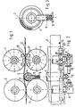
- the device shown is used to produce a metal strip 3 which has successive strip edge deformations 12 in the region of each strip edge.
- the device includes pairs of tool wheels that run in the area of the band edges of the metal band 3. 1 and 2, only one pair of tool wheels with wheels 1, 1 'is shown.
- Each wheel 1, 1 'of the pair of tool wheels carries tools distributed around its circumference in the form of interlocking male parts 10 and female molds 11, which shape the strip edge deformations 12 as the metal strip passes through the tool wheel pair.
- Each pair of tool wheels 1, 1 ' is preceded by a pair of guide wheels with wheels 2, 2', the wheels 2, 2 'of which can have a smooth or roughened surface.
- the pair of tool wheels 1, 1 'and the pair of guide wheels 2, 2' are each connected to a common drive via angular gears 8, a connecting shaft 9 and, for example, an interposed, not shown, speed superposition gear.
- the pair of guide wheels 2, 2 ' has a peripheral speed which corresponds to the transport speed of the metal strip 3.
- the peripheral speed of the pair of tool wheels 1, 1 ′ is somewhat greater than the transport speed of the metal strip 3.
- roller 4 Arranged between the pair of tool wheels 1, 1 'and the pair of guide wheels 2, 2' is a roller 4 which deflects the strip and can be displaced essentially perpendicular to the plane of transport of the metal strip 3.
- the roller is supported on the one hand on the metal strip 3 and, on the other hand, on pins 6, in which it is mounted, on springs 6 which are arranged in spring housings 5.
- the spring housing 5 also serve as a guide for the pin 4 carrying the roller.
- the roller 4 has a jacket 7 made of elastic material, for. B. rubber.
- the device shown in FIGS. 1 to 3 operates as follows.
- the metal strip 3 is fed from the guide wheel pair 2, 2 'at a constant speed. Since the circumferential speed of the wheels of the pair of tool wheels 1, 1 'is somewhat greater than the belt speed, the metal belt 3, when it is gripped by the tools 10, 11, is transported faster than the normal belt speed. To compensate for this speed difference, the roller 4 is biased so that it lifts the metal strip 3 so far out of its transport plane that the tool wheel pair 1, 1 'can carry out its work without there being any constraints in the gears leading to the drive.
- a similar roller 4 can be arranged behind the pair of tool wheels 1, 1 'in the direction of transport in order to limit the unevenness of the strip movement that occurs during embossing to the shortest possible strip length.
- the spring 6 in the spring housing 5 can also be assigned a damping, not shown, in order to dampen undesired band vibrations.
- the tools 10, 11 of the wheels 1, 1 'of the pair of tool wheels can be arranged to be elastically movable in the circumferential direction of the associated wheels 1, 1' in order to introduce vibrational forces into the To reduce or completely avoid wheels 1,1 'or their upstream gear connections to the drive.
- the tools 10, 11 are arranged in associated recesses on the circumference of the wheels 1, 1 '. They are supported in both circumferential directions on the associated walls of the recesses by means of elastic cushions 12, which have an approximately wedge-shaped cross section in the embodiment shown. At the bottom of the recesses, the tools 10, 11 are supported on articulated pins 14 arranged there, the central axes of which extend parallel to the respective wheel axis. This arrangement enables the tools 10, 11 to follow the belt speed when embossing the belt edge deformations, without thereby affecting the speed of rotation of the associated wheels 1, 1 '.
- Fig. 5 it is shown that the recesses for the tools 10, 11 are open towards the end faces of the wheels and that the open sides are closed with support disks 15, which with nuts, not shown, which on threaded pins at the ends of the hinge pin 14th are turned up against the tools 10, 11 are clamped.
- the tools 10, 11 have circumferential grooves, into which elastic rings 16, which are arranged in the inner grooves of the support disks 15, engage.
- the tools 10, 11 are slotted in the longitudinal direction. Locked sleeves 13, whose central axes also extend parallel to the respective wheel axis, supported on the circumferential walls of the recesses of the wheel or on the wheel itself. This also makes the described tilting movement of the tools 10, 11 possible. Otherwise, as in the embodiment according to FIG. 4, the tools 10, 11 have lateral grooves 20 into which the rings 16 (FIG. 5) engage.
- the tools 10, 11 are each housed in associated tool carriers 17 and 18, respectively.
- the tool carriers 17, 18 each have open recesses on the end face, into which the tools 10, 11 are inserted, wherein they are braced in the recesses with support disks 15a covering the open end face ends.
- each tool carrier 17 is supported on an associated circumferential surface of the wheel 1 via a pivot pin 14 so that it can be tilted.
- Adjacent tool carriers 17 are supported against one another via interposed, longitudinally slotted sleeves 13, which are locked on both sides in disks, not shown.
- the arrangement is such that the connecting lines between a sleeve 13 and adjacent hinge pins 14 form a right angle. This results in a tilting movement of a tool carrier 17 without influencing the adjacent tool carrier 17.
- the tool carriers 18 are slidably mounted on a circumferential surface 22 of the wheel 1 'and supported in the circumferential direction of the wheel 1' via springs 21.
- the springs 21 are supported on the one hand on the tool carriers 18 and on the other hand on the projections projecting from the peripheral surface 22 of the wheel 1, with the support points of the springs each lying on the same pitch circle in the embodiment shown.
- tools 19 are inserted into the tool carrier 18, which have both a male and a female.
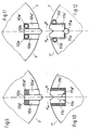
- 9 to 12 show a multi-part embodiment of the tools for generating the edge deformations 12, consisting of the male parts 10a, 10a ', 10c, 10d, 10d' or 10e, 1 Oe ', and the female parts 11a, 11 a ', 11c, 11c' and 11d, 11d 'and 11e.
- the male parts 10a, 10a ' which are elastically supported in the radial direction on the resilient elements 10d, 10d' and 10e, 10e 'and act as hold-down devices, permit their central parts 10c, which act as embossing dies, in conjunction with the resilient elements u in the circumferential direction u on the resilient elements 11 c, 11 c 'or 11 d, 11 d' supported tool parts 11 a, 11 a 'of the tools designed as a split die, depending on the position of the tool wheel pairs 1, 1', differently plunge into the plane of the band 3 and thereby produce them accordingly Belt edge deformations embossed to different depths 12.
- the slight pivoting movement of the tool parts 11a, 11a ' can be facilitated by rounding their lower surfaces with a radius r (FIG. 10) or by means of a hinge pin 11e (FIG. 12).
- the elastic support in the radial direction of the tool parts 10a, 10a 'of the die acting as a hold-down device and the elastic support in the circumferential direction u of the tool parts 11a, 11a' of the die can be achieved by rubber-like support elements 10d, 10d ', 11c, 11c' or by means of metallic springs, for example in the form of slotted sleeves 10e, 10e ', 11d, 11d'.
- the tool parts 10a, 10a ', 10c, 11a, 11 a' can have lateral grooves 20, into which rings 16 according to FIG. 5 engage.
- the tool parts can be provided both in recesses in the tool wheel pairs 1, 1 'with additional elastic support of the tool parts 10a, 10a' in the circumferential direction u by elastic cushions 12 according to FIG. 4 or via sleeves 13 slotted in the longitudinal direction according to FIG. 6, and in tool carriers 17 or 18 according to FIGS. 7 and 8.
Landscapes
- Engineering & Computer Science (AREA)
- Mechanical Engineering (AREA)
- Shaping Metal By Deep-Drawing, Or The Like (AREA)
- Coating With Molten Metal (AREA)
- Metal Rolling (AREA)
- Tires In General (AREA)
- Shaping Of Tube Ends By Bending Or Straightening (AREA)
Claims (15)
Priority Applications (1)
| Application Number | Priority Date | Filing Date | Title |
|---|---|---|---|
| AT85107320T ATE47060T1 (de) | 1984-06-30 | 1985-06-13 | Vorrichtung zum herstellen eines bandes, insbesondere metallbandes mit bandkantenverformung. |
Applications Claiming Priority (2)
| Application Number | Priority Date | Filing Date | Title |
|---|---|---|---|
| DE19848419637U DE8419637U1 (de) | 1984-06-30 | 1984-06-30 | Vorrichtung zum herstellen eines bandes, insbesondere metallbandes mit bandkantenverformungen |
| DE8419637U | 1984-06-30 |
Publications (3)
| Publication Number | Publication Date |
|---|---|
| EP0167874A2 EP0167874A2 (fr) | 1986-01-15 |
| EP0167874A3 EP0167874A3 (en) | 1986-10-08 |
| EP0167874B1 true EP0167874B1 (fr) | 1989-10-11 |
Family
ID=6768381
Family Applications (1)
| Application Number | Title | Priority Date | Filing Date |
|---|---|---|---|
| EP85107320A Expired EP0167874B1 (fr) | 1984-06-30 | 1985-06-13 | Dispositif de fabrication d'un feuillard, en particulier d'un feuillard métallique à bords déformés |
Country Status (5)
| Country | Link |
|---|---|
| US (1) | US4627258A (fr) |
| EP (1) | EP0167874B1 (fr) |
| JP (1) | JPS6120628A (fr) |
| AT (1) | ATE47060T1 (fr) |
| DE (2) | DE8419637U1 (fr) |
Families Citing this family (16)
| Publication number | Priority date | Publication date | Assignee | Title |
|---|---|---|---|---|
| US4711009A (en) * | 1986-02-18 | 1987-12-08 | W. R. Grace & Co. | Process for making metal substrate catalytic converter cores |
| SE463082B (sv) * | 1986-10-24 | 1990-10-08 | Nordisk Kartro Ab | Anordning foer profilering av en stegvis frammatad materialbana |
| CA2079721C (fr) * | 1992-10-02 | 2002-08-20 | Ernest R. Bodnar | Appareil rotatif a matrice mobile |
| US5983693A (en) * | 1995-03-15 | 1999-11-16 | Rotary Press Systems Inc. | Rotary press with cut off apparatus |
| GB9510572D0 (en) * | 1995-05-26 | 1995-07-19 | Metal Box Plc | Containers |
| US5664451A (en) * | 1995-08-02 | 1997-09-09 | Englert/Rollformer, Inc. | Roll forming machine for an indeterminate length metal roof panel |
| GB2311949A (en) * | 1996-03-26 | 1997-10-15 | Hadley Ind Plc | Rigid thin sheet material |
| FR2802596B3 (fr) | 1999-12-17 | 2001-10-26 | Lorraine Laminage | Poutre creuse d'absorption d'energie de choc |
| US6722087B1 (en) | 2000-09-21 | 2004-04-20 | Mic Industries | Building panel and panel crimping machine |
| US7421873B2 (en) * | 2003-05-20 | 2008-09-09 | Showa Denko K.K. | Rolling apparatus and method of making product of miscellaneous cross section with use of same |
| US8104320B2 (en) * | 2008-02-15 | 2012-01-31 | The Boeing Company | Method and apparatus for corrugating sheet metal |
| JP5183342B2 (ja) * | 2008-07-25 | 2013-04-17 | 株式会社Ihi | 固体高分子型燃料電池用セパレータ製造方法及び設備 |
| EP2219191A1 (fr) * | 2008-09-30 | 2010-08-18 | Areva NP | Tuyau de revêtement pour barre de combustion nucléaire, procédé et appareil pour la fabrication du tuyau de revêtement |
| US9925736B2 (en) * | 2013-12-13 | 2018-03-27 | Celltech Metals, Inc. | Sandwich structure |
| CN107073464A (zh) * | 2014-10-15 | 2017-08-18 | Acat环球公司 | 扇形折叠结合式金属催化剂基板及其构造方法 |
| DE102015101580B3 (de) * | 2015-02-04 | 2016-06-02 | Hydro Aluminium Rolled Products Gmbh | Verfahren und Vorrichtung zum Prägewalzen eines Bandes |
Family Cites Families (13)
| Publication number | Priority date | Publication date | Assignee | Title |
|---|---|---|---|---|
| US1657695A (en) * | 1928-01-31 | Machine | ||
| US1148670A (en) * | 1914-03-12 | 1915-08-03 | Fedders Mfg Co Inc | Metal-bending machine. |
| US2082456A (en) * | 1934-07-25 | 1937-06-01 | Klangfilm Gmbh | Arrangement for recording, reproducing, and printing films |
| US2022082A (en) * | 1935-03-08 | 1935-11-26 | Streine Tool And Mfg Company | Die for two-roll corrugating machines |
| US2257760A (en) * | 1939-07-12 | 1941-10-07 | Agnes J Reeves Greer | Formation of metal coils |
| US2669452A (en) * | 1951-12-29 | 1954-02-16 | Gen Precision Lab Inc | Sound stabilization system |
| US3239912A (en) * | 1962-01-15 | 1966-03-15 | Bennett American Corp | Continuous forging method |
| DE1950708A1 (de) * | 1969-10-08 | 1971-04-15 | Kloeckner Werke Ag | Verfahren und Vorrichtungen zum Kuehlen von Metallbaendern |
| DE2015100C3 (de) * | 1970-03-28 | 1973-10-11 | Wilkening, Hermann, Dr.-Ing., 4000 Duesseldorf-Kaiserswerth | Metallband für einen gewickelten Bund mit freiem Raum zwischen den Windungen und Vonchtung zur Herstellung dieses Me tallbandes |
| US4160371A (en) * | 1975-06-04 | 1979-07-10 | Iog Industrie-Ofenbau Gmbh | Apparatus for making a spiral coil having spaced turns |
| DE2524763C3 (de) * | 1975-06-04 | 1982-07-08 | IOG Industrie-Ofenbau GmbH, 4000 Düsseldorf | Metallband für einen gewickelten Bund und Vorrichtung zur Herstellung des Metallbandes |
| DD120601A1 (fr) * | 1975-07-03 | 1976-06-20 | ||
| US4269342A (en) * | 1979-03-15 | 1981-05-26 | Ellinor Daniel H | Resiliently stabilized web movement for honeycomb machine |
-
1984
- 1984-06-30 DE DE19848419637U patent/DE8419637U1/de not_active Expired
-
1985
- 1985-06-13 DE DE8585107320T patent/DE3573544D1/de not_active Expired
- 1985-06-13 EP EP85107320A patent/EP0167874B1/fr not_active Expired
- 1985-06-13 AT AT85107320T patent/ATE47060T1/de not_active IP Right Cessation
- 1985-07-01 US US06/750,856 patent/US4627258A/en not_active Expired - Fee Related
- 1985-07-01 JP JP60142679A patent/JPS6120628A/ja active Granted
Also Published As
| Publication number | Publication date |
|---|---|
| EP0167874A2 (fr) | 1986-01-15 |
| JPS6120628A (ja) | 1986-01-29 |
| DE8419637U1 (de) | 1984-10-11 |
| EP0167874A3 (en) | 1986-10-08 |
| US4627258A (en) | 1986-12-09 |
| DE3573544D1 (en) | 1989-11-16 |
| ATE47060T1 (de) | 1989-10-15 |
| JPH0472620B2 (fr) | 1992-11-18 |
Similar Documents
| Publication | Publication Date | Title |
|---|---|---|
| EP0167874B1 (fr) | Dispositif de fabrication d'un feuillard, en particulier d'un feuillard métallique à bords déformés | |
| EP2588273B1 (fr) | Machine servant à réaliser un galetage de renforcement sur des axes d'essieux | |
| DE2327846C3 (de) | Vorrichtung zum Abrichten einer Schleifscheibe | |
| EP0243795B1 (fr) | Dispositif pour guider des viroles arrondies à travers une zône de soudage | |
| DE1452724A1 (de) | Walzmaschine mit schraegen Walzen | |
| DE69832426T2 (de) | Pressvorrichtung für Metallblech | |
| DE2605124C2 (de) | Vorrichtung zur Herstellung von Fahrzeugreifen, im Schleudergußverfahren | |
| DE3131107A1 (de) | "vorrichtung zur einstellung der drehachse eines gelenks zur schwenkfaehigen aufhaengung eines fuehrungslenkers eines rades am aufbau eines kraftfahrzeuges" | |
| DE2115680C3 (de) | Vorrichtung zum Abstreifen von gummielastischen Ringen von einem Kern einer Preßform | |
| DE3001271A1 (de) | Zufuehrungseinrichtung vom walzentyp zum zufuehren von flaechigem material | |
| EP0913232A1 (fr) | Appareil pour l'usinage de pièces cylindriques | |
| EP0185299A1 (fr) | Dispositif de guidage ininterrompu pour châssis arrondis dans une machine de soudage en continu | |
| EP3349915A1 (fr) | Dispositif d'usinage de bande et procédé d'usinage d'une bande | |
| DE1217602B (de) | Aufbaumaschine fuer den Flachaufbau von Fahrzeugreifen | |
| DE2418316C2 (de) | Wickelmaschine für Blechbänder | |
| DE1574639B2 (de) | Vorrichtung zum ausrichten eines in einer richtung bewegbaren bandes oder bandabschnittes aus klebrigem reifenbaumaterial in bezug auf eine zur foerderrichtung parallele lotrechte bezugsebene | |
| DE102013106268A1 (de) | Verfahren und Vorrichtung zur Herstellung rotationssymmetrischer Metallbauteile | |
| DE2723231B2 (de) | Maschine zum Abrunden mit einem vorbestimmten Radius der Ecken von Glasplatten | |
| DE3044142C2 (de) | Geräteträger zur dreiachsig verstellbaren Abstützung eines Gerätes | |
| DE60004510T2 (de) | Vorrichtung zum zentrieren eines kontinuierlichen bands, insbesonder für eine blisterpackungen produzierende maschine | |
| DE2656773C2 (de) | Vorrichtung zum Verändern des Abstandes zweier einander gegenüberliegender Stütz- bzw. Führungsrollen einer Stranggießanlage | |
| DE1941186B2 (de) | Rollenwechsler für Rollenrichtmaschinen | |
| EP0009079A1 (fr) | Machine à fraiser les vilebrequins | |
| EP0305559A1 (fr) | Dispositif de pressage pour machines de collage des bords, de postformage ou de revêtement travaillant en continu | |
| DE3033015C2 (de) | Antriebsriemen mit Vierkantprofil aus Gummi oder gummiartigem Werkstoff sowie Verfahren und Vorrichtung zu seiner Herstellung |
Legal Events
| Date | Code | Title | Description |
|---|---|---|---|
| PUAI | Public reference made under article 153(3) epc to a published international application that has entered the european phase |
Free format text: ORIGINAL CODE: 0009012 |
|
| AK | Designated contracting states |
Designated state(s): AT BE DE FR GB IT |
|
| PUAL | Search report despatched |
Free format text: ORIGINAL CODE: 0009013 |
|
| AK | Designated contracting states |
Kind code of ref document: A3 Designated state(s): AT BE DE FR GB IT |
|
| 17P | Request for examination filed |
Effective date: 19861021 |
|
| 17Q | First examination report despatched |
Effective date: 19880226 |
|
| GRAA | (expected) grant |
Free format text: ORIGINAL CODE: 0009210 |
|
| AK | Designated contracting states |
Kind code of ref document: B1 Designated state(s): AT BE DE FR GB IT |
|
| REF | Corresponds to: |
Ref document number: 47060 Country of ref document: AT Date of ref document: 19891015 Kind code of ref document: T |
|
| REF | Corresponds to: |
Ref document number: 3573544 Country of ref document: DE Date of ref document: 19891116 |
|
| ITF | It: translation for a ep patent filed |
Owner name: UFFICIO BREVETTI RICCARDI & C. |
|
| GBT | Gb: translation of ep patent filed (gb section 77(6)(a)/1977) | ||
| ET | Fr: translation filed | ||
| PLBE | No opposition filed within time limit |
Free format text: ORIGINAL CODE: 0009261 |
|
| STAA | Information on the status of an ep patent application or granted ep patent |
Free format text: STATUS: NO OPPOSITION FILED WITHIN TIME LIMIT |
|
| 26N | No opposition filed | ||
| ITTA | It: last paid annual fee | ||
| PGFP | Annual fee paid to national office [announced via postgrant information from national office to epo] |
Ref country code: AT Payment date: 19940620 Year of fee payment: 10 |
|
| PGFP | Annual fee paid to national office [announced via postgrant information from national office to epo] |
Ref country code: GB Payment date: 19940701 Year of fee payment: 10 |
|
| PGFP | Annual fee paid to national office [announced via postgrant information from national office to epo] |
Ref country code: BE Payment date: 19940706 Year of fee payment: 10 |
|
| PG25 | Lapsed in a contracting state [announced via postgrant information from national office to epo] |
Ref country code: GB Effective date: 19950613 Ref country code: AT Effective date: 19950613 |
|
| PG25 | Lapsed in a contracting state [announced via postgrant information from national office to epo] |
Ref country code: BE Effective date: 19950630 |
|
| BERE | Be: lapsed |
Owner name: IOG INDUSTRIE-OFENBAU G.M.B.H. Effective date: 19950630 |
|
| GBPC | Gb: european patent ceased through non-payment of renewal fee |
Effective date: 19950613 |
|
| PGFP | Annual fee paid to national office [announced via postgrant information from national office to epo] |
Ref country code: FR Payment date: 19970616 Year of fee payment: 13 |
|
| PGFP | Annual fee paid to national office [announced via postgrant information from national office to epo] |
Ref country code: DE Payment date: 19970709 Year of fee payment: 13 |
|
| PG25 | Lapsed in a contracting state [announced via postgrant information from national office to epo] |
Ref country code: FR Free format text: LAPSE BECAUSE OF NON-PAYMENT OF DUE FEES Effective date: 19990226 |
|
| PG25 | Lapsed in a contracting state [announced via postgrant information from national office to epo] |
Ref country code: DE Free format text: LAPSE BECAUSE OF NON-PAYMENT OF DUE FEES Effective date: 19990401 |
|
| REG | Reference to a national code |
Ref country code: FR Ref legal event code: ST |