EP0167874B1 - Device for manufacturing strip, in particular metal strip with deformed strip edges - Google Patents
Device for manufacturing strip, in particular metal strip with deformed strip edges Download PDFInfo
- Publication number
- EP0167874B1 EP0167874B1 EP85107320A EP85107320A EP0167874B1 EP 0167874 B1 EP0167874 B1 EP 0167874B1 EP 85107320 A EP85107320 A EP 85107320A EP 85107320 A EP85107320 A EP 85107320A EP 0167874 B1 EP0167874 B1 EP 0167874B1
- Authority
- EP
- European Patent Office
- Prior art keywords
- wheels
- pair
- strip
- tool
- tools
- Prior art date
- Legal status (The legal status is an assumption and is not a legal conclusion. Google has not performed a legal analysis and makes no representation as to the accuracy of the status listed.)
- Expired
Links
- 239000002184 metal Substances 0.000 title claims abstract description 15
- 238000004519 manufacturing process Methods 0.000 title 1
- 238000004049 embossing Methods 0.000 claims description 8
- 239000013013 elastic material Substances 0.000 claims description 5
- 238000011144 upstream manufacturing Methods 0.000 claims description 3
- 230000000717 retained effect Effects 0.000 claims 2
- 238000007493 shaping process Methods 0.000 abstract 1
- 239000000969 carrier Substances 0.000 description 11
- 230000002093 peripheral effect Effects 0.000 description 4
- 238000004804 winding Methods 0.000 description 3
- 244000059549 Borneo rubber Species 0.000 description 1
- 238000013016 damping Methods 0.000 description 1
- 230000001419 dependent effect Effects 0.000 description 1
- 230000001360 synchronised effect Effects 0.000 description 1
Images

Classifications
-
- B—PERFORMING OPERATIONS; TRANSPORTING
- B21—MECHANICAL METAL-WORKING WITHOUT ESSENTIALLY REMOVING MATERIAL; PUNCHING METAL
- B21C—MANUFACTURE OF METAL SHEETS, WIRE, RODS, TUBES OR PROFILES, OTHERWISE THAN BY ROLLING; AUXILIARY OPERATIONS USED IN CONNECTION WITH METAL-WORKING WITHOUT ESSENTIALLY REMOVING MATERIAL
- B21C47/00—Winding-up, coiling or winding-off metal wire, metal band or other flexible metal material characterised by features relevant to metal processing only
- B21C47/26—Special arrangements with regard to simultaneous or subsequent treatment of the material
-
- B—PERFORMING OPERATIONS; TRANSPORTING
- B21—MECHANICAL METAL-WORKING WITHOUT ESSENTIALLY REMOVING MATERIAL; PUNCHING METAL
- B21D—WORKING OR PROCESSING OF SHEET METAL OR METAL TUBES, RODS OR PROFILES WITHOUT ESSENTIALLY REMOVING MATERIAL; PUNCHING METAL
- B21D13/00—Corrugating sheet metal, rods or profiles; Bending sheet metal, rods or profiles into wave form
- B21D13/04—Corrugating sheet metal, rods or profiles; Bending sheet metal, rods or profiles into wave form by rolling
-
- B—PERFORMING OPERATIONS; TRANSPORTING
- B21—MECHANICAL METAL-WORKING WITHOUT ESSENTIALLY REMOVING MATERIAL; PUNCHING METAL
- B21D—WORKING OR PROCESSING OF SHEET METAL OR METAL TUBES, RODS OR PROFILES WITHOUT ESSENTIALLY REMOVING MATERIAL; PUNCHING METAL
- B21D19/00—Flanging or other edge treatment, e.g. of tubes
- B21D19/02—Flanging or other edge treatment, e.g. of tubes by continuously-acting tools moving along the edge
- B21D19/04—Flanging or other edge treatment, e.g. of tubes by continuously-acting tools moving along the edge shaped as rollers
-
- B—PERFORMING OPERATIONS; TRANSPORTING
- B21—MECHANICAL METAL-WORKING WITHOUT ESSENTIALLY REMOVING MATERIAL; PUNCHING METAL
- B21D—WORKING OR PROCESSING OF SHEET METAL OR METAL TUBES, RODS OR PROFILES WITHOUT ESSENTIALLY REMOVING MATERIAL; PUNCHING METAL
- B21D43/00—Feeding, positioning or storing devices combined with, or arranged in, or specially adapted for use in connection with, apparatus for working or processing sheet metal, metal tubes or metal profiles; Associations therewith of cutting devices
- B21D43/02—Advancing work in relation to the stroke of the die or tool
- B21D43/021—Control or correction devices in association with moving strips
- B21D43/022—Loop-control
Definitions
- the invention relates to a device for producing a band, in particular metal band, which has local band edge deformations, with at least one pair of tool wheels, the wheels of which have patrices or matrices arranged around the circumference for embossing the band edge deformations, and with a pair of guide wheels connected upstream of the tool wheel pair, the wheels of which are synchronous circulate to the belt speed.
- the object of the invention is to increase the operating speed of a device of the type described above.
- a roller which is essentially perpendicular to the plane of transport of the belt is arranged, which is supported on the one hand on the belt and on the other hand resiliently, and the pair of tool wheels is rigidly coupled to the pair of guide wheels via a gear.
- This role deflects the belt from its transport plane between the pair of guide wheels and the pair of tool wheels and absorbs at least part of the torsional vibrations caused by the uneven working speed of the pair of tool wheels to such an extent that, according to a preferred embodiment of the invention, the pair of tool wheels is also rigidly connected to the gearbox Guide wheel pair can be coupled and its wheels can have a peripheral speed that is greater than the belt speed. In practice, the vibrations of the pair of tool wheels are shifted onto the belt itself.
- the unevenness of the belt movements produced in this way can be restricted to a very short belt length, in particular if a similar roller is arranged behind the pair of tool wheels in the transport direction of the belt.
- a simple, preferred embodiment of the roller is characterized in that the roller is mounted on pins which are displaceably guided in spring housings. A further reduction in the vibrations is achieved if the roller has a jacket made of elastic material.
- the forces introduced into the tool wheel pair or the vibrations resulting therefrom can be further reduced and the working speed increased if the tools of the tool wheel pair are arranged to be elastically movable in the circumferential direction of the assigned wheels. For that there are different possibilities.
- the tools can be arranged in assigned recesses of the wheels, supported on the base of the recesses on hinge pins and on the walls of the recesses via resilient elements. Accordingly, at the time of stamping, the tools perform a tilting movement around the hinge pins while their associated wheels rotate at a constant speed. After the embossing, the tools are returned to their rest position by the resilient elements.
- the resilient elements can be longitudinally slotted tube sleeves which are arranged in the region of the walls of the recess.
- the elements can also be made of elastic material in which the tools are embedded.
- the recesses of the wheels can be open towards the end faces thereof, the tools being held between supporting disks covering the open end faces of the recesses.
- the tools can also be held in associated tool carriers, which are arranged to be elastically movable in the circumferential direction of the wheels.
- the tool carriers can also be supported on the wheels by means of pivot pins and mutually by means of resilient elements, in particular slotted tubular sleeves. A mutual influence of the movements of adjacent tool carriers is largely ruled out if the connecting lines between the central axes of a tubular sleeve and the adjacent hinge pin enclose a right angle in a projection onto the end face of a wheel.
- the tool carriers can be mounted displaceably in the circumferential direction on a circumferential surface of the wheel in question and can be supported on the wheel via elements that are resilient in the circumferential direction.
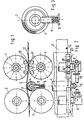
- the device shown is used to produce a metal strip 3 which has successive strip edge deformations 12 in the region of each strip edge.
- the device includes pairs of tool wheels that run in the area of the band edges of the metal band 3. 1 and 2, only one pair of tool wheels with wheels 1, 1 'is shown.
- Each wheel 1, 1 'of the pair of tool wheels carries tools distributed around its circumference in the form of interlocking male parts 10 and female molds 11, which shape the strip edge deformations 12 as the metal strip passes through the tool wheel pair.
- Each pair of tool wheels 1, 1 ' is preceded by a pair of guide wheels with wheels 2, 2', the wheels 2, 2 'of which can have a smooth or roughened surface.
- the pair of tool wheels 1, 1 'and the pair of guide wheels 2, 2' are each connected to a common drive via angular gears 8, a connecting shaft 9 and, for example, an interposed, not shown, speed superposition gear.
- the pair of guide wheels 2, 2 ' has a peripheral speed which corresponds to the transport speed of the metal strip 3.
- the peripheral speed of the pair of tool wheels 1, 1 ′ is somewhat greater than the transport speed of the metal strip 3.
- roller 4 Arranged between the pair of tool wheels 1, 1 'and the pair of guide wheels 2, 2' is a roller 4 which deflects the strip and can be displaced essentially perpendicular to the plane of transport of the metal strip 3.
- the roller is supported on the one hand on the metal strip 3 and, on the other hand, on pins 6, in which it is mounted, on springs 6 which are arranged in spring housings 5.
- the spring housing 5 also serve as a guide for the pin 4 carrying the roller.
- the roller 4 has a jacket 7 made of elastic material, for. B. rubber.
- the device shown in FIGS. 1 to 3 operates as follows.
- the metal strip 3 is fed from the guide wheel pair 2, 2 'at a constant speed. Since the circumferential speed of the wheels of the pair of tool wheels 1, 1 'is somewhat greater than the belt speed, the metal belt 3, when it is gripped by the tools 10, 11, is transported faster than the normal belt speed. To compensate for this speed difference, the roller 4 is biased so that it lifts the metal strip 3 so far out of its transport plane that the tool wheel pair 1, 1 'can carry out its work without there being any constraints in the gears leading to the drive.
- a similar roller 4 can be arranged behind the pair of tool wheels 1, 1 'in the direction of transport in order to limit the unevenness of the strip movement that occurs during embossing to the shortest possible strip length.
- the spring 6 in the spring housing 5 can also be assigned a damping, not shown, in order to dampen undesired band vibrations.
- the tools 10, 11 of the wheels 1, 1 'of the pair of tool wheels can be arranged to be elastically movable in the circumferential direction of the associated wheels 1, 1' in order to introduce vibrational forces into the To reduce or completely avoid wheels 1,1 'or their upstream gear connections to the drive.
- the tools 10, 11 are arranged in associated recesses on the circumference of the wheels 1, 1 '. They are supported in both circumferential directions on the associated walls of the recesses by means of elastic cushions 12, which have an approximately wedge-shaped cross section in the embodiment shown. At the bottom of the recesses, the tools 10, 11 are supported on articulated pins 14 arranged there, the central axes of which extend parallel to the respective wheel axis. This arrangement enables the tools 10, 11 to follow the belt speed when embossing the belt edge deformations, without thereby affecting the speed of rotation of the associated wheels 1, 1 '.
- Fig. 5 it is shown that the recesses for the tools 10, 11 are open towards the end faces of the wheels and that the open sides are closed with support disks 15, which with nuts, not shown, which on threaded pins at the ends of the hinge pin 14th are turned up against the tools 10, 11 are clamped.
- the tools 10, 11 have circumferential grooves, into which elastic rings 16, which are arranged in the inner grooves of the support disks 15, engage.
- the tools 10, 11 are slotted in the longitudinal direction. Locked sleeves 13, whose central axes also extend parallel to the respective wheel axis, supported on the circumferential walls of the recesses of the wheel or on the wheel itself. This also makes the described tilting movement of the tools 10, 11 possible. Otherwise, as in the embodiment according to FIG. 4, the tools 10, 11 have lateral grooves 20 into which the rings 16 (FIG. 5) engage.
- the tools 10, 11 are each housed in associated tool carriers 17 and 18, respectively.
- the tool carriers 17, 18 each have open recesses on the end face, into which the tools 10, 11 are inserted, wherein they are braced in the recesses with support disks 15a covering the open end face ends.
- each tool carrier 17 is supported on an associated circumferential surface of the wheel 1 via a pivot pin 14 so that it can be tilted.
- Adjacent tool carriers 17 are supported against one another via interposed, longitudinally slotted sleeves 13, which are locked on both sides in disks, not shown.
- the arrangement is such that the connecting lines between a sleeve 13 and adjacent hinge pins 14 form a right angle. This results in a tilting movement of a tool carrier 17 without influencing the adjacent tool carrier 17.
- the tool carriers 18 are slidably mounted on a circumferential surface 22 of the wheel 1 'and supported in the circumferential direction of the wheel 1' via springs 21.
- the springs 21 are supported on the one hand on the tool carriers 18 and on the other hand on the projections projecting from the peripheral surface 22 of the wheel 1, with the support points of the springs each lying on the same pitch circle in the embodiment shown.
- tools 19 are inserted into the tool carrier 18, which have both a male and a female.
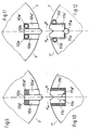
- 9 to 12 show a multi-part embodiment of the tools for generating the edge deformations 12, consisting of the male parts 10a, 10a ', 10c, 10d, 10d' or 10e, 1 Oe ', and the female parts 11a, 11 a ', 11c, 11c' and 11d, 11d 'and 11e.
- the male parts 10a, 10a ' which are elastically supported in the radial direction on the resilient elements 10d, 10d' and 10e, 10e 'and act as hold-down devices, permit their central parts 10c, which act as embossing dies, in conjunction with the resilient elements u in the circumferential direction u on the resilient elements 11 c, 11 c 'or 11 d, 11 d' supported tool parts 11 a, 11 a 'of the tools designed as a split die, depending on the position of the tool wheel pairs 1, 1', differently plunge into the plane of the band 3 and thereby produce them accordingly Belt edge deformations embossed to different depths 12.
- the slight pivoting movement of the tool parts 11a, 11a ' can be facilitated by rounding their lower surfaces with a radius r (FIG. 10) or by means of a hinge pin 11e (FIG. 12).
- the elastic support in the radial direction of the tool parts 10a, 10a 'of the die acting as a hold-down device and the elastic support in the circumferential direction u of the tool parts 11a, 11a' of the die can be achieved by rubber-like support elements 10d, 10d ', 11c, 11c' or by means of metallic springs, for example in the form of slotted sleeves 10e, 10e ', 11d, 11d'.
- the tool parts 10a, 10a ', 10c, 11a, 11 a' can have lateral grooves 20, into which rings 16 according to FIG. 5 engage.
- the tool parts can be provided both in recesses in the tool wheel pairs 1, 1 'with additional elastic support of the tool parts 10a, 10a' in the circumferential direction u by elastic cushions 12 according to FIG. 4 or via sleeves 13 slotted in the longitudinal direction according to FIG. 6, and in tool carriers 17 or 18 according to FIGS. 7 and 8.
Landscapes
- Engineering & Computer Science (AREA)
- Mechanical Engineering (AREA)
- Shaping Metal By Deep-Drawing, Or The Like (AREA)
- Metal Rolling (AREA)
- Coating With Molten Metal (AREA)
- Tires In General (AREA)
- Shaping Of Tube Ends By Bending Or Straightening (AREA)
Abstract
Description
Die Erfindung betrifft eine Vorrichtung zum Herstellen eines Bandes, insbesondere Metallbandes, das örtliche Bandkantenverformungen aufweist, mit wenigstens einem Werkzeugradpaar, dessen Räder am Umfang verteilt angeordnete Patrizen bzw. Matrizen zum Prägen der Bandkantenverformungen aufweisen, und mit einem dem Werkzeugradpaar vorgeschalteten Führungsradpaar, dessen Räder synchron zur Bandgeschwindigkeit umlaufen.The invention relates to a device for producing a band, in particular metal band, which has local band edge deformations, with at least one pair of tool wheels, the wheels of which have patrices or matrices arranged around the circumference for embossing the band edge deformations, and with a pair of guide wheels connected upstream of the tool wheel pair, the wheels of which are synchronous circulate to the belt speed.
Bänder, insbesondere Metallbänder mit Bandkantenverformungen sind bekannt (DE-B 2015100). Die längs des Bandes in Abständen angeordneten Bandkantenverformungen sollen sich beim Aufwickeln des Bandes zu einem Bandring mit den vorangehenden, am Auflaufpunkt in Wickelrichtung vorhandenen Bandkantenverformungen so verhaken, daß ein stabiler Bandring entsteht.Tapes, in particular metal tapes with tape edge deformations are known (DE-B 2015100). The band edge deformations, which are arranged at intervals along the band, should interlock when winding the band into a band ring with the preceding band edge deformations present at the point of run-up in the winding direction in such a way that a stable band ring is formed.
Bei einer bekannten Vorrichtung der eingangs beschriebenen Gattung (DE-C 25 24 763) wird das durch geringfügig unterschiedliche Geschwindigkeiten einerseits des Bandes und andererseits der Werkzeuge am Umfang der Werkzeugtragräder in Abhängigkeit von Banddicke und Windungsabstand erreicht. Da jedoch im Moment des Prägens der Bandkantenverformungen die Geschwindigkeiten des Bandes und der Werkzeuge gleich sein müssen, sind die Werkzeugtragräder über elastische Verbindungen an ihren zugeordneten Antrieb angeschlossen. Anders ausgedrückt werden im Moment des Prägens die Werkzeugtragräder vom Band mitgenommen und anschließend wieder freigegeben, so daß eine von der Arbeitsgeschwindigkeit abhängige Drehschwingung der Werkzeugtragräder entsteht, die der Arbeitsgeschwindigkeit Grenzen setzt.In a known device of the type described at the beginning (DE-C 25 24 763), this is achieved by slightly different speeds of the belt on the one hand and of the tools on the other hand on the circumference of the tool carrier wheels depending on the belt thickness and the winding spacing. However, since the speeds of the strip and the tools must be the same at the moment the strip edge deformations are shaped, the tool carrier wheels are connected to their assigned drive via elastic connections. In other words, at the moment of stamping, the tool carrier wheels are taken off the belt and then released again, so that a torsional vibration of the tool carrier wheels, which is dependent on the working speed, occurs, which limits the working speed.
Aufgabe der Erfindung ist es, die Arbeitsgeschwindigkeit einer Vorrichtung der eingangs beschriebenen Gattung zu erhöhen.The object of the invention is to increase the operating speed of a device of the type described above.
Diese Aufgabe wird dadurch gelöst, daß zwischen dem Führungsradpaar und dem Werkzeugradpaar eine im wesentlichen senkrecht zur Transportebene des Bandes verschiebliche Rolle angeordnet ist, die einerseits am Band und andererseits federnd abgestützt ist und das Werkzeugradpaar über ein Getriebe starr an das Führungsradpaar gekoppelt ist.This object is achieved in that between the pair of guide wheels and the pair of tool wheels, a roller which is essentially perpendicular to the plane of transport of the belt is arranged, which is supported on the one hand on the belt and on the other hand resiliently, and the pair of tool wheels is rigidly coupled to the pair of guide wheels via a gear.
Diese Rolle lenkt das Band aus seiner Transportebene zwischen dem Führungsradpaar und dem Werkzeugradpaar aus und absorbiert zumindest einen Teil der durch die Ungleichmäßigkeit der Arbeitsgeschwindigkeit des Werkzeugradpaares verursachten Drehschwingungen in einem solchen Maße, daß nach bevorzugter Ausführung der Erfindung das Werkzeugradpaar auch über ein Getriebe starr an das Führungsradpaar gekoppelt sein kann und seine Räder eine Umfangsgeschwindigkeit aufweisen können, die größer als die Bandgeschwindigkeit ist. Praktisch werden dadurch die Schwingungen des Werkzeugradpaares auf das Band selbst verlagert.This role deflects the belt from its transport plane between the pair of guide wheels and the pair of tool wheels and absorbs at least part of the torsional vibrations caused by the uneven working speed of the pair of tool wheels to such an extent that, according to a preferred embodiment of the invention, the pair of tool wheels is also rigidly connected to the gearbox Guide wheel pair can be coupled and its wheels can have a peripheral speed that is greater than the belt speed. In practice, the vibrations of the pair of tool wheels are shifted onto the belt itself.
Die dadurch erzeugten Ungleichmäßigkeiten der Bandbewegungen können auf eine sehr kurze Bandlänge insbesondere dann beschränkt bleiben, wenn in Transportrichtung des Bandes hinter dem Werkzeugradpaar eine gleichartige Rolle angeordnet ist.The unevenness of the belt movements produced in this way can be restricted to a very short belt length, in particular if a similar roller is arranged behind the pair of tool wheels in the transport direction of the belt.
Eine einfache, bevorzugte Ausführung der Rolle ist dadurch gekennzeichnet, daß die Rolle an Zapfen gelagert ist, die verschieblich in Federgehäusen geführt sind. Eine weitere Reduzierung der Schwingungen erreicht man dann, wenn die Rolle einen Mantel aus elastischem Material aufweist.A simple, preferred embodiment of the roller is characterized in that the roller is mounted on pins which are displaceably guided in spring housings. A further reduction in the vibrations is achieved if the roller has a jacket made of elastic material.
Die in das Werkzeugradpaar eingeleiteten Kräfte bzw. die daraus resultierenden Schwingungen lassen sich weiter reduzieren und die Arbeitsgeschwindigkeit vergrößern, wenn die Werkzeuge des Werkzeugradpaares in Umfangsrichtung der zugeordneten Räder elastisch beweglich angeordnet sind. Dazu gibt es verschiedene Möglichkeiten.The forces introduced into the tool wheel pair or the vibrations resulting therefrom can be further reduced and the working speed increased if the tools of the tool wheel pair are arranged to be elastically movable in the circumferential direction of the assigned wheels. For that there are different possibilities.
Die Werkzeuge können in zugeordneten Ausnehmungen der Räder angeordnet, am Grund der Ausnehmungen auf Gelenkbolzen sowie an den Wandungen der Ausnehmungen über federnde Elemente abgestützt sein. Dementsprechend führen die Werkzeuge zur Zeit des Prägens eine Kippbewegung um die Gelenkbolzen aus, während ihre zugeordneten Räder mit gleichbleibender Geschwindigkeit umlaufen. Nach dem Prägen werden die Werkzeuge von den federnden Elementen wieder in ihre Ruhestellung zurückgeführt Die federnden Elemente können längsgeschlitzte Rohrhülsen sein, die im Bereich der Wandungen der Ausnehmung angeordnet sind. Die Elemente können aber auch aus elastischem Material sein, in die die Werkzeuge eingebettet sind.The tools can be arranged in assigned recesses of the wheels, supported on the base of the recesses on hinge pins and on the walls of the recesses via resilient elements. Accordingly, at the time of stamping, the tools perform a tilting movement around the hinge pins while their associated wheels rotate at a constant speed. After the embossing, the tools are returned to their rest position by the resilient elements. The resilient elements can be longitudinally slotted tube sleeves which are arranged in the region of the walls of the recess. The elements can also be made of elastic material in which the tools are embedded.
Im übrigen können die Ausnehmungen der Räder zu deren Stirnseiten hin offen sein, wobei die Werkzeuge zwischen die offenen Stirnseiten der Ausnehmungen abdeckenden Stützscheiben gehalten sind.In addition, the recesses of the wheels can be open towards the end faces thereof, the tools being held between supporting disks covering the open end faces of the recesses.
Die Werkzeuge können aber auch in zugeordneten Werkzeugträgern gehalten sein, die in Umfangsrichtung der Räder elastisch beweglich angeordnet sind. Auch die Werkzeugträger können über Gelenkbolzen auf den Rädern und gegenseitig über federnde Elemente, insbesondere geschlitzte Rohrhülsen, abgestützt sein. Eine gegenseitige Beeinflussung der Bewegungen benachbarter Werkzeugträger wird weitgehend ausgeschlossen, wenn in einer Projektion auf die Stirnseite eines Rades die Verbindungslinien zwischen den Mittelachsen einer Rohrhülse und der benachbarten Gelenkbolzen einen rechten Winkel einschließen.However, the tools can also be held in associated tool carriers, which are arranged to be elastically movable in the circumferential direction of the wheels. The tool carriers can also be supported on the wheels by means of pivot pins and mutually by means of resilient elements, in particular slotted tubular sleeves. A mutual influence of the movements of adjacent tool carriers is largely ruled out if the connecting lines between the central axes of a tubular sleeve and the adjacent hinge pin enclose a right angle in a projection onto the end face of a wheel.
Bei einer anderen Ausführung können die Werkzeugträger auf einer Umfangsfläche des betreffenden Rades in Umfangsrichtung verschieblich gelagert und über in Umfangsrichtung federnde Elemente am Rad abgestützt sein.In another embodiment, the tool carriers can be mounted displaceably in the circumferential direction on a circumferential surface of the wheel in question and can be supported on the wheel via elements that are resilient in the circumferential direction.
Im folgenden werden in der Zeichnung dargestellte Ausführungsbeispiele der Erfindung erläutert ; es zeigen :
- Fig. 1 in schematischer Darstellung und teilweise die Seitenansicht einer Vorrichtung zum Herstellen eines Bandes mit Bandkantenverformungen,
- Fig. 2 in schematischer Darstellung eine Draufsicht auf den Gegenstand nach Fig. 1,
- Fig. 3 schematisch und in vergrößerter Darstellung einen Teil des Gegenstandes nach Fig. 1,
- Fig. 4 teilweise eine andere Ausführung des Gegenstandes nach Fig. 1,
- Fig. 5 einen Radialschnitt durch den Gegenstand nach Fig. 4,
- Fig. 6 bis 12 teilweise weitere Ausführungen des Gegenstandes nach Fig. 1.
- 1 in a schematic representation and partially the side view of a device for producing a band with band edge deformations,
- 2 shows a schematic representation of a top view of the object according to FIG. 1,
- 3 schematically and in an enlarged view a part of the object according to FIG. 1,
- 4 partially another embodiment of the object according to FIG. 1,
- 5 shows a radial section through the object according to FIG. 4,
- 6 to 12 partially further versions of the object of FIG. 1st
Die dargestellte Vorrichtung dient zur Herstellung eines Metallbandes 3, das im Bereich jeder Bandkante aufeinanderfolgende Bandkantenverformungen 12 aufweist. Zu der Vorrichtung gehören Werkzeugradpaare, die im Bereich der Bandkanten des Metallbandes 3 laufen. In den Fig. 1 und 2 ist nur ein Werkzeugradpaar mit Rädern 1,1' dargestellt. Jedes Rad 1,1' des Werkzeugradpaares trägt an seinem Umfang verteilt angeordnete Werkzeuge in Form von ineinandergreifenden Patrizen 10 und Matrizen 11, die beim Durchlauf des Metallbandes durch das Werkzeugradpaar die Bandkantenverformungen 12 prägen.The device shown is used to produce a metal strip 3 which has successive
Jedem Werkzeugradpaar 1,1' ist ein Führungsradpaar mit Rädern 2,2' vorgeschaltet, dessen Räder 2,2' eine glatte oder gerauhte Oberfläche aufweisen können.Each pair of
Das Werkzeugradpaar 1,1' und das Führungsradpaar 2,2' sind jeweils über Winkelgetriebe 8, eine Verbindungswelle 9 und beispielsweise ein zwischengeschaltetes, nicht dargestelltes Drehzahlüberlagerungsgetriebe an einen gemeinsamen Antrieb angeschlossen. Das Führungsradpaar 2,2' besitzt eine Umfangseschwindigkeit, die der Transportgeschwindigkeit des Metallbandes 3 entspricht. Die Umfangsgeschwindigkeit des Werkzeugradpaares 1,1' ist etwas großer als die Transportgeschwindigkeit des Metallbandes 3.The pair of
Zwischen dem Werkzeugradpaar 1,1' und dem Führungsradpaar 2,2' ist eine das Band ablenkende Rolle 4 angeordnet, die im wesentlichen senkrecht zur Transportebene des Metallbandes 3 verschieblich ist. Dazu ist die Rolle einerseits am Metallband 3 und andererseits über Zapfen, in den sie gelagert ist, auf Federn 6 abgestützt, die in Federgehaüsen 5 angeordnet sind. Die Federgehäuse 5 dienen gleichzeitig auch als Führung für die die Rolle 4 tragenden Zapfen. Die Rolle 4 besitzt einen Mantel 7 aus elastischem Material, z. B. Gummi.Arranged between the pair of
Die in den Fig. 1 bis 3 dargestellte Vorrichtung arbeitet wie folgt. Das Metallband 3 wird vom Führungsradpaar 2,2' mit konstanter Geschwindigkeit zugeführt. Da die Umfangsgeschwindigkeit der Räder des Werkzeugradpaares 1,1' etwas größer ist als die Bandgeschwindigkeit, wird das Metallband 3 dann, wenn es von den Werkzeugen 10, 11 erfaßt wird, schneller transportiert als der normalen Bandgeschwindigkeit entspricht. Zum Ausgleich dieser Geschwindigkeitsdifferenz ist die Rolle 4 so vorgespannt, daß sie das Metallband 3 so weit aus seiner Transportebene heraushebt, daß das Werkzeugradpaar 1,1' seine Arbeit ausführen kann, ohne daß es zu Zwängungen in den zum Antrieb führenden Getrieben kommen kann. Die beim Prägen der Bandkantenverformungen 12 erforderliche zusätzliche Bandlänge ergibt sich aus einer Streckung des zwischen dem Werkzeugradpaar 1,1' und dem Führungsradpaar 2,2' über die Rolle 4 geführten Bandabschnitts, indem die Rolle 4 federnd auf die Federgehäuse 5 zurückgedrückt wird. Wenn die Prägung abgeschlossen ist, nimmt die Rolle 4 wieder ihre in Fig. 1 dargestellte Position ein, wobei der zwischen dem Werkzeugradpaar 1,1' und dem Führungsradpaar 2,2' befindliche Bandabschnitt um ein entsprechendes Stück verlängert ist.The device shown in FIGS. 1 to 3 operates as follows. The metal strip 3 is fed from the
Nicht dargestellt ist, daß in Transportrichtung hinter dem Werkzeugradpaar 1,1' eine gleichartige Rolle 4 angeordnet sein kann, um die beim Prägen entstehende Ungleichmäßigkeit der Bandbewegung auf eine möglichst kurze Bandlänge zu beschränken.It is not shown that a
Es versteht sich, daß der Feder 6 im Federgehäuse 5 auch eine nicht dargestellte Dämpfung zugeordnet sein kann, um unerwünschte Bandschwingungen zu dämpfen.It goes without saying that the
In den Fig. 4 und 6 bis 8 ist dargestellt, daß auch die Werkzeuge 10, 11 der Räder 1,1' des Werkzeugradpaares in Umfangsrichtung der zugeordneten Räder 1,1' elastisch beweglich angeordnet sein können, um die Einleitung von schwingungserregenden Kräften in die Räder 1,1' bzw. deren vorgeschaltete getriebliche Verbindungen zum Antrieb zu reduzieren oder ganz zu vermeiden.4 and 6 to 8 it is shown that the
Bei der in Fig. 4 dargestellten Ausführung sind die Werkzeuge 10, 11 in zugeordneten Ausnehmungen am Umfang der Räder 1,1' angeordnet. Sie sind in beiden Umfangsrichtungen über elastische Kissen 12, die bei der dargestellten Ausführung ungefähr keilförmigen Querschnitt besitzen, an den zugeordneten Wandungen der Ausnehmungen abgestützt. Am Grund der Ausnehmungen sind die Werkzeuge 10, 11 auf dort angeordneten Gelenkbolzen 14, deren Mittelachsen sich parallel zur jeweiligen Radachse erstrecken, kippbeweglich abgestützt. Diese Anordnung ermöglicht es den Werkzeugen 10, 11 beim Prägen der Bandkantenverformungen der Bandgeschwindigkeit zu folgen, ohne daß dadurch die Drehgeschwindigkeit der zugeordneten Räder 1,1' beeinträchtig wird.In the embodiment shown in FIG. 4, the
In Fig. 5 ist dargestellt, daß die Ausnehmungen für die Werkzeuge 10, 11 zu den Stirnseiten der Räder hin offen sind und daß die offenen Seiten mit Stützscheiben 15 geschlossen sind, die mit nicht dargestellten Muttern, welche auf Gewindezapfen an den Enden der Gelenkbolzen 14 aufgedreht sind, gegen die Werkzeuge 10, 11 gespannt werden. Die Werkzeuge 10, 11 besitzen dazu Umfangsrillen, in die elastische Ringe 16, welche in innenseitigen Nuten der Stützscheiben 15 angeordnet sind, eingreifen.In Fig. 5 it is shown that the recesses for the
Bei der in Fig. 6 dargestellten Ausführung sind die Werkzeuge 10, 11 über in Längsrichtung geschlitzte. Hülsen 13 arretiert, deren Mittelachsen sich ebenfalls parallel zur jeweiligen Radachse erstrecken, an den in Umfangsrichtung liegenden Wandungen der Ausnehmungen des Rades bzw. am Rad selbst abgestützt. Auch dadurch ist die beschriebene Kippbewegung der Werkzeuge 10, 11 möglich. Im übrigen besitzen die Werkzeuge 10, 11, ebenso wie bei der Ausführung nach Fig. 4, seitliche Rillen 20, in die die Ringe 16 (Fig. 5) eingreifen.In the embodiment shown in FIG. 6, the
Bei den in den Fig. 7 und 8 dargestellten Ausführungen sind die Werkzeuge 10, 11 jeweils in zugeordneten Werkzeugträgem 17 bzw. 18 untergebracht. Die Werkzeugträger 17, 18 weisen jeweils stirnseitig offene Ausnehmungen auf, in die die Werkzeuge 10, 11 eingesetzt sind, wobei sie mit die offenen Stirnseiten abdeckenden Stützscheiben 15a in den Ausnehmungen verspannt sind.In the embodiments shown in FIGS. 7 and 8, the
Bei der in Fig. 7 dargestellten Ausführung ist jeder Werkzeugträger 17 auf einer zugeordneten Umfangsfläche des Rades 1 über einen Gelenkbolzen 14 kippbeweglich abgestützt. Benachbarte Werkzeugträger 17 sind über zwischengeschaltete, längsgeschlitzte, beiderseits in nicht dargestellten Scheiben arretierten Hülsen 13 gegeneinander abgestützt. Die Anordnung ist im einzelnen so, daß die Verbindungslinien zwischen einer Hülse 13 und benachbarten Gelenkbolzen 14 einen rechten Winkel bilden. Dadurch erfolgt eine Kippbewegung eines Werkzeugträgers 17 ohne Beeinflussung des benachbarten Werkzeugträgers 17.In the embodiment shown in FIG. 7, each
Bei der Ausführung nach Fig. 8 sind die Werkzeugträger 18 auf einer Umfangsfläche 22 des Rades 1' gleitend verschieblich gelagert sowie über Federn 21 in Umfangsrichtung des Rades 1' abgestützt. Die Federn 21 sind einerseits an den Werkzeugträgern 18 und andererseits an die Umfangsfläche 22 des Rades 1 überragenden Vorsprüngen abgestützt, wobei bei der dargestellten Ausführung die Abstützpunkte der Federn jeweils auf dem gleichen Teilkreis liegen. Bei der Ausführung nach Fig. 8 sind in die Werkzeugträger 18 Werkzeuge 19 eingesetzt, die sowohl eine Patrize als auch eine Matrize aufweisen.8, the
Die Befestigung dieser Werkzeuge 19 in den zugeordneten Werkzeugträgem erfolgt, wie oben beschrieben, mit Hilfe von die Stirnseiten der offenen Ausnehmungen abdeckenden Stützscheiben 15a.These
In den Fig. 9 bis 12 ist eine mehrteilige Ausführungsform der Werkzeuge für die Erzeugung der Kantenverformungen 12 dargestellt, bestehend aus den Patrizenteilen 10a, 10a', 10c, 10d, 10d' bzw. 10e, 1 Oe', sowie den Matrizenteilen 11 a, 11 a', 11c, 11c' bzw. 11d, 11d' und 11e.9 to 12 show a multi-part embodiment of the tools for generating the
Die elastisch auf den federnd nachgiebigen Elementen 10d, 10d' bzw. 10e, 10e' in radialer Richtung abgestützten, als Niederhalter wirksamen Patrizenteile 10a, 10a' gestatten ihren als Prägestempel wirksamen Mittelteilen 10c in Verbindung mit den in Umfangsrichtung u elastisch nachgiebig an den federnden Elementen 11 c, 11 c' bzw. 11 d, 11 d' abgestützten Werkzeugteilen 11 a, 11 a' der als geteilte Matrize ausgebildeten Werkzeuge ein je nach Anstellung der Werkzeugradpaare 1,1' unterschiedliches Eintauchen in die Ebene des Bandes 3 und erzeugen dadurch entsprechend unterschiedlich tief geprägte Bandkantenverformungen 12.The
Die geringe Schwenkbewegung der Werkzeugteile 11a, 11 a' läßt sich durch Abrundungen ihrer Unterflächen mit einem Radius r (Fig. 10) oder durch einen Gelenkbolzen 11e (Fig. 12) erleichtem. Die elastische Abstützung in radialer Richtung der als Niederhalter wirkenden Werkzeugteile 10a, 10a' der Matrize sowie die elastische Abstützung in Umfangsrichtung u der Werkzeugteile 11 a, 11 a' der Matrize kann durch gummiähnliche Abstützelemente 10d, 10d', 11 c, 11 c' oder durch metallische Federn, beispielsweise in Form geschlitzter Hülsen 10e, 10e', 11d, 11d' erfolgen.The slight pivoting movement of the
Die Werkzeugteile 10a, 10a', 10c, 11a, 11 a' können ebenso wie bei der Ausführungsform nach Fig. 4 seitliche Rillen 20 besitzen, in die Ringe 16 nach Fig. 5 eingreifen. Die Werkzeugteile können sowohl in Ausnehmungen der Werkzeugradpaare 1,1' mit zusätzlicher elastischer Abstützung der Werkzeugteile 10a, 10a' in Umfangsrichtung u durch elastische Kissen 12 nach Fig. 4 bzw. über in Längsrichtung geschlitzte Hülsen 13 nach Fig. 6 als auch in Werkzeugträgern 17 bzw. 18 nach Fig. 7 und Fig. 8 untergebracht sein.As in the embodiment according to FIG. 4, the
Claims (15)
Priority Applications (1)
| Application Number | Priority Date | Filing Date | Title |
|---|---|---|---|
| AT85107320T ATE47060T1 (en) | 1984-06-30 | 1985-06-13 | DEVICE FOR PRODUCTION OF A STRIP, IN PARTICULAR METAL STRIP WITH STRIP EDGE DEFORMATION. |
Applications Claiming Priority (2)
| Application Number | Priority Date | Filing Date | Title |
|---|---|---|---|
| DE8419637U | 1984-06-30 | ||
| DE19848419637U DE8419637U1 (en) | 1984-06-30 | 1984-06-30 | DEVICE FOR PRODUCING A TAPE, IN PARTICULAR METAL TAPE WITH TAPE EDGING |
Publications (3)
| Publication Number | Publication Date |
|---|---|
| EP0167874A2 EP0167874A2 (en) | 1986-01-15 |
| EP0167874A3 EP0167874A3 (en) | 1986-10-08 |
| EP0167874B1 true EP0167874B1 (en) | 1989-10-11 |
Family
ID=6768381
Family Applications (1)
| Application Number | Title | Priority Date | Filing Date |
|---|---|---|---|
| EP85107320A Expired EP0167874B1 (en) | 1984-06-30 | 1985-06-13 | Device for manufacturing strip, in particular metal strip with deformed strip edges |
Country Status (5)
| Country | Link |
|---|---|
| US (1) | US4627258A (en) |
| EP (1) | EP0167874B1 (en) |
| JP (1) | JPS6120628A (en) |
| AT (1) | ATE47060T1 (en) |
| DE (2) | DE8419637U1 (en) |
Families Citing this family (16)
| Publication number | Priority date | Publication date | Assignee | Title |
|---|---|---|---|---|
| US4711009A (en) * | 1986-02-18 | 1987-12-08 | W. R. Grace & Co. | Process for making metal substrate catalytic converter cores |
| SE463082B (en) * | 1986-10-24 | 1990-10-08 | Nordisk Kartro Ab | DEVICE FOR PROFILING A STEP FORMATED MATERIAL COVER |
| US5983693A (en) * | 1995-03-15 | 1999-11-16 | Rotary Press Systems Inc. | Rotary press with cut off apparatus |
| CA2079721C (en) * | 1992-10-02 | 2002-08-20 | Ernest R. Bodnar | Rotary apparatus with moveable die |
| GB9510572D0 (en) * | 1995-05-26 | 1995-07-19 | Metal Box Plc | Containers |
| US5664451A (en) * | 1995-08-02 | 1997-09-09 | Englert/Rollformer, Inc. | Roll forming machine for an indeterminate length metal roof panel |
| GB2311949A (en) | 1996-03-26 | 1997-10-15 | Hadley Ind Plc | Rigid thin sheet material |
| FR2802596B3 (en) | 1999-12-17 | 2001-10-26 | Lorraine Laminage | HOLLOW BEAM FOR ABSORPTION OF SHOCK ENERGY |
| US6722087B1 (en) * | 2000-09-21 | 2004-04-20 | Mic Industries | Building panel and panel crimping machine |
| WO2004103590A1 (en) * | 2003-05-20 | 2004-12-02 | Showa Denko K.K. | Rolling apparatus and method of making product of miscellaneous cross section with use of same |
| US8104320B2 (en) * | 2008-02-15 | 2012-01-31 | The Boeing Company | Method and apparatus for corrugating sheet metal |
| JP5183342B2 (en) * | 2008-07-25 | 2013-04-17 | 株式会社Ihi | Separator manufacturing method and equipment for polymer electrolyte fuel cell |
| EP2219191A1 (en) * | 2008-09-30 | 2010-08-18 | Areva NP | Cladding tube for nuclear fuel rod, method and apparatus for manufacturing a cladding tube |
| US9925736B2 (en) * | 2013-12-13 | 2018-03-27 | Celltech Metals, Inc. | Sandwich structure |
| US20170226914A1 (en) * | 2014-10-15 | 2017-08-10 | Acat Global | Fan fold bonded metal catalyst substrate and method for constructing the same |
| DE102015101580B3 (en) * | 2015-02-04 | 2016-06-02 | Hydro Aluminium Rolled Products Gmbh | Method and device for embossing a strip |
Family Cites Families (13)
| Publication number | Priority date | Publication date | Assignee | Title |
|---|---|---|---|---|
| US1657695A (en) * | 1928-01-31 | Machine | ||
| US1148670A (en) * | 1914-03-12 | 1915-08-03 | Fedders Mfg Co Inc | Metal-bending machine. |
| US2082456A (en) * | 1934-07-25 | 1937-06-01 | Klangfilm Gmbh | Arrangement for recording, reproducing, and printing films |
| US2022082A (en) * | 1935-03-08 | 1935-11-26 | Streine Tool And Mfg Company | Die for two-roll corrugating machines |
| US2257760A (en) * | 1939-07-12 | 1941-10-07 | Agnes J Reeves Greer | Formation of metal coils |
| US2669452A (en) * | 1951-12-29 | 1954-02-16 | Gen Precision Lab Inc | Sound stabilization system |
| US3239912A (en) * | 1962-01-15 | 1966-03-15 | Bennett American Corp | Continuous forging method |
| DE1950708A1 (en) * | 1969-10-08 | 1971-04-15 | Kloeckner Werke Ag | Cooling of metal strip |
| DE2015100C3 (en) * | 1970-03-28 | 1973-10-11 | Wilkening, Hermann, Dr.-Ing., 4000 Duesseldorf-Kaiserswerth | Metal band for a wound collar with free space between the turns and caution for the production of this metal band |
| US4160371A (en) * | 1975-06-04 | 1979-07-10 | Iog Industrie-Ofenbau Gmbh | Apparatus for making a spiral coil having spaced turns |
| DE2524763C3 (en) * | 1975-06-04 | 1982-07-08 | IOG Industrie-Ofenbau GmbH, 4000 Düsseldorf | Metal band for a wound collar and device for producing the metal band |
| DD120601A1 (en) * | 1975-07-03 | 1976-06-20 | ||
| US4269342A (en) * | 1979-03-15 | 1981-05-26 | Ellinor Daniel H | Resiliently stabilized web movement for honeycomb machine |
-
1984
- 1984-06-30 DE DE19848419637U patent/DE8419637U1/en not_active Expired
-
1985
- 1985-06-13 AT AT85107320T patent/ATE47060T1/en not_active IP Right Cessation
- 1985-06-13 DE DE8585107320T patent/DE3573544D1/en not_active Expired
- 1985-06-13 EP EP85107320A patent/EP0167874B1/en not_active Expired
- 1985-07-01 US US06/750,856 patent/US4627258A/en not_active Expired - Fee Related
- 1985-07-01 JP JP60142679A patent/JPS6120628A/en active Granted
Also Published As
| Publication number | Publication date |
|---|---|
| EP0167874A2 (en) | 1986-01-15 |
| DE8419637U1 (en) | 1984-10-11 |
| ATE47060T1 (en) | 1989-10-15 |
| EP0167874A3 (en) | 1986-10-08 |
| JPS6120628A (en) | 1986-01-29 |
| DE3573544D1 (en) | 1989-11-16 |
| JPH0472620B2 (en) | 1992-11-18 |
| US4627258A (en) | 1986-12-09 |
Similar Documents
| Publication | Publication Date | Title |
|---|---|---|
| EP0167874B1 (en) | Device for manufacturing strip, in particular metal strip with deformed strip edges | |
| EP2588273B1 (en) | Machine for deep-rolling axles | |
| DE2327846C3 (en) | Device for dressing a grinding wheel | |
| EP0243795B1 (en) | Device for guiding rounded borders through a welding zone | |
| DE69832426T2 (en) | Pressing device for sheet metal | |
| DE2605124C2 (en) | Device for the production of vehicle tires, in the centrifugal casting process | |
| DE3131107A1 (en) | Device for adjusting the axis of rotation of a joint for the swivellable suspension of a radius arm of a wheel on the body of a motor vehicle | |
| DE2115680B2 (en) | DEVICE FOR STRIPPING RUBBER-ELASTIC RINGS FROM A CORE OF A PRESSING FORM | |
| DE69126025T2 (en) | DEVICE FOR APPLYING TIRE COMPONENTS | |
| DE3001271A1 (en) | FEEDER DEVICE FROM ROLLER TYPE FOR FEEDING FLAT MATERIAL | |
| EP0913232A1 (en) | Apparatus for machining cylindrical surfaces | |
| EP0185299A1 (en) | Pass-through guiding device of a seam-welding machine for the production of tubular blanks | |
| EP3349915A1 (en) | Strip processing device and method for processing a strip | |
| DE1217602B (en) | Construction machine for the flat construction of vehicle tires | |
| DE2418316C2 (en) | Winding machine for sheet metal strips | |
| EP4003644B1 (en) | Device for processing the borders of flat workpieces | |
| DE102013106268A1 (en) | Method and device for producing rotationally symmetrical metal components | |
| DE2937819A1 (en) | UNDERFLOOR WHEEL LATHE | |
| DE3611399C2 (en) | Transmission device for driving a wheel body shaping device | |
| DE69703513T2 (en) | Method and device for forming a leaf spring eye | |
| DE2723231B2 (en) | Machine for rounding the corners of glass sheets with a predetermined radius | |
| DE10037015B4 (en) | Wing groove grinding device for internal grinding of a compressor cylinder | |
| DE68910347T2 (en) | Manufacture of electrical pens. | |
| DE60004510T2 (en) | DEVICE FOR CENTERING A CONTINUOUS BAND, IN PARTICULAR FOR A MACHINE PRODUCING A BLISTER PACK | |
| DE2656773C2 (en) | Device for changing the distance between two opposing support or guide rollers in a continuous caster |
Legal Events
| Date | Code | Title | Description |
|---|---|---|---|
| PUAI | Public reference made under article 153(3) epc to a published international application that has entered the european phase |
Free format text: ORIGINAL CODE: 0009012 |
|
| AK | Designated contracting states |
Designated state(s): AT BE DE FR GB IT |
|
| PUAL | Search report despatched |
Free format text: ORIGINAL CODE: 0009013 |
|
| AK | Designated contracting states |
Kind code of ref document: A3 Designated state(s): AT BE DE FR GB IT |
|
| 17P | Request for examination filed |
Effective date: 19861021 |
|
| 17Q | First examination report despatched |
Effective date: 19880226 |
|
| GRAA | (expected) grant |
Free format text: ORIGINAL CODE: 0009210 |
|
| AK | Designated contracting states |
Kind code of ref document: B1 Designated state(s): AT BE DE FR GB IT |
|
| REF | Corresponds to: |
Ref document number: 47060 Country of ref document: AT Date of ref document: 19891015 Kind code of ref document: T |
|
| REF | Corresponds to: |
Ref document number: 3573544 Country of ref document: DE Date of ref document: 19891116 |
|
| ITF | It: translation for a ep patent filed | ||
| GBT | Gb: translation of ep patent filed (gb section 77(6)(a)/1977) | ||
| ET | Fr: translation filed | ||
| PLBE | No opposition filed within time limit |
Free format text: ORIGINAL CODE: 0009261 |
|
| STAA | Information on the status of an ep patent application or granted ep patent |
Free format text: STATUS: NO OPPOSITION FILED WITHIN TIME LIMIT |
|
| 26N | No opposition filed | ||
| ITTA | It: last paid annual fee | ||
| PGFP | Annual fee paid to national office [announced via postgrant information from national office to epo] |
Ref country code: AT Payment date: 19940620 Year of fee payment: 10 |
|
| PGFP | Annual fee paid to national office [announced via postgrant information from national office to epo] |
Ref country code: GB Payment date: 19940701 Year of fee payment: 10 |
|
| PGFP | Annual fee paid to national office [announced via postgrant information from national office to epo] |
Ref country code: BE Payment date: 19940706 Year of fee payment: 10 |
|
| PG25 | Lapsed in a contracting state [announced via postgrant information from national office to epo] |
Ref country code: GB Effective date: 19950613 Ref country code: AT Effective date: 19950613 |
|
| PG25 | Lapsed in a contracting state [announced via postgrant information from national office to epo] |
Ref country code: BE Effective date: 19950630 |
|
| BERE | Be: lapsed |
Owner name: IOG INDUSTRIE-OFENBAU G.M.B.H. Effective date: 19950630 |
|
| GBPC | Gb: european patent ceased through non-payment of renewal fee |
Effective date: 19950613 |
|
| PGFP | Annual fee paid to national office [announced via postgrant information from national office to epo] |
Ref country code: FR Payment date: 19970616 Year of fee payment: 13 |
|
| PGFP | Annual fee paid to national office [announced via postgrant information from national office to epo] |
Ref country code: DE Payment date: 19970709 Year of fee payment: 13 |
|
| PG25 | Lapsed in a contracting state [announced via postgrant information from national office to epo] |
Ref country code: FR Free format text: LAPSE BECAUSE OF NON-PAYMENT OF DUE FEES Effective date: 19990226 |
|
| PG25 | Lapsed in a contracting state [announced via postgrant information from national office to epo] |
Ref country code: DE Free format text: LAPSE BECAUSE OF NON-PAYMENT OF DUE FEES Effective date: 19990401 |
|
| REG | Reference to a national code |
Ref country code: FR Ref legal event code: ST |