EP0165486A2 - Dispositif de montage flottant du carter d'une pompe centrifuge à un moteur éléctrique - Google Patents
Dispositif de montage flottant du carter d'une pompe centrifuge à un moteur éléctrique Download PDFInfo
- Publication number
- EP0165486A2 EP0165486A2 EP85106154A EP85106154A EP0165486A2 EP 0165486 A2 EP0165486 A2 EP 0165486A2 EP 85106154 A EP85106154 A EP 85106154A EP 85106154 A EP85106154 A EP 85106154A EP 0165486 A2 EP0165486 A2 EP 0165486A2
- Authority
- EP
- European Patent Office
- Prior art keywords
- housing
- pump
- bearing
- electric motor
- pump housing
- Prior art date
- Legal status (The legal status is an assumption and is not a legal conclusion. Google has not performed a legal analysis and makes no representation as to the accuracy of the status listed.)
- Granted
Links
Images

Classifications
-
- F—MECHANICAL ENGINEERING; LIGHTING; HEATING; WEAPONS; BLASTING
- F04—POSITIVE - DISPLACEMENT MACHINES FOR LIQUIDS; PUMPS FOR LIQUIDS OR ELASTIC FLUIDS
- F04D—NON-POSITIVE-DISPLACEMENT PUMPS
- F04D29/00—Details, component parts, or accessories
- F04D29/04—Shafts or bearings, or assemblies thereof
- F04D29/046—Bearings
- F04D29/049—Roller bearings
-
- F—MECHANICAL ENGINEERING; LIGHTING; HEATING; WEAPONS; BLASTING
- F04—POSITIVE - DISPLACEMENT MACHINES FOR LIQUIDS; PUMPS FOR LIQUIDS OR ELASTIC FLUIDS
- F04D—NON-POSITIVE-DISPLACEMENT PUMPS
- F04D29/00—Details, component parts, or accessories
- F04D29/04—Shafts or bearings, or assemblies thereof
- F04D29/043—Shafts
- F04D29/044—Arrangements for joining or assembling shafts
-
- F—MECHANICAL ENGINEERING; LIGHTING; HEATING; WEAPONS; BLASTING
- F04—POSITIVE - DISPLACEMENT MACHINES FOR LIQUIDS; PUMPS FOR LIQUIDS OR ELASTIC FLUIDS
- F04D—NON-POSITIVE-DISPLACEMENT PUMPS
- F04D29/00—Details, component parts, or accessories
- F04D29/04—Shafts or bearings, or assemblies thereof
- F04D29/046—Bearings
- F04D29/0462—Bearing cartridges
-
- F—MECHANICAL ENGINEERING; LIGHTING; HEATING; WEAPONS; BLASTING
- F04—POSITIVE - DISPLACEMENT MACHINES FOR LIQUIDS; PUMPS FOR LIQUIDS OR ELASTIC FLUIDS
- F04D—NON-POSITIVE-DISPLACEMENT PUMPS
- F04D29/00—Details, component parts, or accessories
- F04D29/60—Mounting; Assembling; Disassembling
- F04D29/62—Mounting; Assembling; Disassembling of radial or helico-centrifugal pumps
- F04D29/628—Mounting; Assembling; Disassembling of radial or helico-centrifugal pumps especially adapted for liquid pumps
Definitions
- the invention relates to a device for the flying arrangement and attachment of a pump housing, in particular a K pump pump housing on a drive device, in particular an electric motor, with the interposition of a lantern housing, the device being drive-centered via a first recess on the drive device and fastened by connecting means and centered on the pump side via a second recess on the pump housing and fastened via connecting means.
- a known device of the type mentioned above is always used, for example, when centrifugal pumps for conveying tasks in the food and beverage sector have to be arranged and attached to a standardized or standardized electric motor.
- the pumping tasks and the internal and external cleaning procedures on the pump usually require a pump made of corrosion-resistant steel. Since the mortar part on the pump side should have approximately the same corrosion resistance as the pump housing, and standardized or standardized electric motors do not have this material property in the area of their end shield, the known device has, in addition to its connecting function still the function of a protective shield shielding the pump-side motor part. It is therefore made of corrosion-resistant steel, just like the drive shaft led out of the electric motor.
- the task is also to be solved with an electric motor which, with the exception of its pump-side bearing shield, consists of a standardized or standardized, unchanged and therefore inexpensive family of parts.
- the bearing plate of the electric motor is directly preferably integrally connected, with a aternengeratiuse Lagerqephaseuse and an L and indirectly via the aternengephaseuse L is preferably integrally connected with a Vorkeh tion for positive and / or non-positive connection with the pump housing, and that the entire device is made of a suitable, in particular corrosion-resistant material.
- the device can be made extremely compact, in particular in the axial direction to save space.
- the lantern housing has a lower lantern opening at least on the underside in order to discharge leaks in the installed position of the end shield.
- the lantern housing which is generally necessary between the electric motor and the pump housing, is formed directly on the pump housing
- the lantern housing is dispensed with in the latter.
- the provision for the positive and / or non-positive connection with the pump housing is located directly on the end shield.
- the device according to the invention may be advantageous to design as a welded construction from the simplest possible geometrical basic bodies or as a cast construction or as a combined cast and welded construction.
- Another advantageous embodiment of the device according to the invention allows an adjustment and non-rotatable mounting of a cover of the electric motor on the pump-side end shield. This is achieved in that on the side facing the pump housing of the end shield there is provided a central, cylindrical projection and two bolts outside the cylindrical projection in the lower part and at a distance from one another and projecting from the receiving surface.
- one foot in the free end faces of the foot holders, which are arranged and fastened at a distance on the underside of the end shield in the installed position, one foot can be axially adjusted via a threaded bolt and can be locked via a lock nut.
- the pump-side sealing of a roller bearing is particularly simple and therefore inexpensive if, according to a further advantageous embodiment of the device according to the invention, a pump-side bearing cover is axially clamped between the roller bearing and the bearing housing within a bearing bore, which covers a shaft with play and from one to the latter co-arranged splash ring is sealingly contacted.
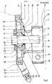
- a centrifugal pump housing 3 (FIG. 1) is arranged on an electric motor 2 by means of a device 1 according to the invention and fastened to it. Two feet, not specified, on the device 1 and a third foot on the electric motor 2 carry the entire pump unit. A cover 4 is placed over the entire electric motor 2, which covers part of the device 1 and is supported on it at the same time.
- the device according to the invention is embodied as a welded construction in FIG. 2 by way of example. It consists essentially of a plate-shaped bearing plate la, which is centered and fixed via a bearing plate recess 1m on a motor recess 2a on the housing of the electric motor 2, a bearing housing lb, a lantern housing 1d and a precaution lc, 1g, 1h for positive connection with a cylindrical one Seal housing 3a of a pump housing 3.
- the bearing housing 1b is sleeve-shaped in the area of the end shield la and is centered within a central end shield bore 1p over its outer lateral surface.
- An unspecified collar of the bearing housing 1b rests against the pump-side end face of the endshield 1b and is welded to it all around via a weld seam lr.
- the lantern housing 1d and, in its continuation, a terminal housing lc adjoin the aforementioned collar.
- the lantern housing 1d has openings on its upper and lower sides, an upper and a lower lantern opening le and lf, respectively.
- the clamp housing 1c is completely slotted on its underside into the lower lantern opening 1f.
- a likewise slotted, horseshoe-shaped clamping part 1g is welded in each case to the opposite ends of the clamping housing 1c in such a way that it bridges its slot, so that the clamping housing 1c and the clamping part 1g together result in a closed contour.
- the two legs of the clamping part 1g are provided with a bore 1h for a connecting means, whereby a receiving bore 1k formed by the clamping housing 1c can be radially reduced within narrow limits.
- the elastic deformability of the clamp housing 1c in the region of the clamp part 1g is promoted by the lower lantern opening lf.
- the fastening of the seal housing 3a of the pump housing 3 within the receiving bore lk is ensured in the exemplary embodiment exclusively by a non-positive connection.
- the end shield la is equipped on its outer edge outside its end shield recess lm with a plurality of flange bores ln distributed over its circumference. They serve to accommodate connecting means, not shown and designated, by means of which the end shield 1a is fastened directly to the housing of the electric motor 2.
- two foot brackets la are welded, each of which axially adjustable a foot 12 in a free end face via a threaded bolt 13 and lockable via a lock nut 11.
- a central, cylindrical projection 11 and two bolts which are recessed in the lower part and at a distance from one another outside the cylindrical projection 11 and protrude beyond the receiving surface, not shown and designated.
- the cylindrical approach 1 serves to center and fix the cover 4; the bolts engage in an associated contour of the hood 4 and secure it against rotation.
- the bearing housing 1b is provided with a central bearing bore li, which is delimited by a collar on the pump side within the bearing housing 1b and is limited to a passage which is not described in more detail bore for a shaft 5 is reduced.
- roller bearing 7 designed as a fixed bearing, the outer ring of which is fixed between a bearing cover 6 fastened to the bearing housing 1b and a pump-side bearing cover 9 which surrounds the shaft 5 with play on the inside and abuts the bearing bore li delimited on the outside.
- a displacement of the shaft 5 in the direction of the pump housing 3 is prevented by a shaft collar 5 a, which bears against the inner ring of the roller bearing 7.
- the motor-side bearing cover 6 is screwed to the bearing housing 1b via connecting means, not shown and designated, which are accommodated in the bearing housing bores 10. It has a recess 6a facing the roller bearing 7, in which a shaft seal 8 is arranged.
- the shaft sealing on the pump side takes place via a splash ring 10 which is arranged on the shaft 5 and which makes sealing contact with the bearing cover 9 on the pump side.
- the device according to the invention may be advantageous to produce it as a cast part or as a combination of a cast and welded part. So it makes sense, for example, to design bearing plate 1a and bearing housing lb as a cast or forged part, while lanterns and Terminal housing 1d and 1c made from a tubular semi-finished product and then the USS to the above-mentioned G or forged part to be welded. The final machining process is then carried out on the composite construction.
Landscapes
- Engineering & Computer Science (AREA)
- Mechanical Engineering (AREA)
- General Engineering & Computer Science (AREA)
- Structures Of Non-Positive Displacement Pumps (AREA)
- Feeding And Controlling Fuel (AREA)
Priority Applications (1)
| Application Number | Priority Date | Filing Date | Title |
|---|---|---|---|
| AT85106154T ATE48027T1 (de) | 1984-05-23 | 1985-05-20 | Vorrichtung zur fliegenden anordnung und befestigung eines kreisel-pumpengehaeuses an eine antriebsvorrichtung. |
Applications Claiming Priority (2)
| Application Number | Priority Date | Filing Date | Title |
|---|---|---|---|
| DE8415722U | 1984-05-23 | ||
| DE8415722U DE8415722U1 (de) | 1984-05-23 | 1984-05-23 | Vorrichtung zur fliegenden Anordnung und Befestigung eines Pumpengehäuses an eine Antriebsvorrichtung |
Publications (3)
| Publication Number | Publication Date |
|---|---|
| EP0165486A2 true EP0165486A2 (fr) | 1985-12-27 |
| EP0165486A3 EP0165486A3 (en) | 1987-05-27 |
| EP0165486B1 EP0165486B1 (fr) | 1989-11-15 |
Family
ID=6767189
Family Applications (1)
| Application Number | Title | Priority Date | Filing Date |
|---|---|---|---|
| EP85106154A Expired EP0165486B1 (fr) | 1984-05-23 | 1985-05-20 | Dispositif de montage flottant du carter d'une pompe centrifuge à un moteur éléctrique |
Country Status (3)
| Country | Link |
|---|---|
| EP (1) | EP0165486B1 (fr) |
| AT (1) | ATE48027T1 (fr) |
| DE (2) | DE8415722U1 (fr) |
Citations (3)
| Publication number | Priority date | Publication date | Assignee | Title |
|---|---|---|---|---|
| US1435400A (en) * | 1921-07-25 | 1922-11-14 | Mahlon E Layne | Electric drive mechanism for rotary well pumps |
| US3433164A (en) * | 1967-03-03 | 1969-03-18 | Buffalo Forge Co | Motor-pump unit |
| FR2316457A1 (fr) * | 1975-07-02 | 1977-01-28 | Sihi Gmbh & Co Kg | Groupe moteur-pompe centrifuge |
-
1984
- 1984-05-23 DE DE8415722U patent/DE8415722U1/de not_active Expired
-
1985
- 1985-05-20 DE DE8585106154T patent/DE3574275D1/de not_active Expired
- 1985-05-20 EP EP85106154A patent/EP0165486B1/fr not_active Expired
- 1985-05-20 AT AT85106154T patent/ATE48027T1/de not_active IP Right Cessation
Patent Citations (3)
| Publication number | Priority date | Publication date | Assignee | Title |
|---|---|---|---|---|
| US1435400A (en) * | 1921-07-25 | 1922-11-14 | Mahlon E Layne | Electric drive mechanism for rotary well pumps |
| US3433164A (en) * | 1967-03-03 | 1969-03-18 | Buffalo Forge Co | Motor-pump unit |
| FR2316457A1 (fr) * | 1975-07-02 | 1977-01-28 | Sihi Gmbh & Co Kg | Groupe moteur-pompe centrifuge |
Non-Patent Citations (1)
| Title |
|---|
| Hellmuth Schulz: "Die Pumpen", 13.Auflage 1977 Springer Verlag Seiten 220-223 * |
Also Published As
| Publication number | Publication date |
|---|---|
| EP0165486A3 (en) | 1987-05-27 |
| DE8415722U1 (de) | 1985-07-11 |
| DE3574275D1 (en) | 1989-12-21 |
| ATE48027T1 (de) | 1989-12-15 |
| EP0165486B1 (fr) | 1989-11-15 |
Similar Documents
| Publication | Publication Date | Title |
|---|---|---|
| DE4315826C5 (de) | Motor-Pumpen-Aggregat | |
| DE10152497A1 (de) | Nassläuferpumpe | |
| EP0323834A2 (fr) | Pompe sans étanchéite | |
| DE3328484A1 (de) | Pumpe, insbesondere fass- oder tauchpumpe | |
| EP0344587B1 (fr) | Carter de construction en ligne | |
| DE4024313C2 (fr) | ||
| EP0918932B1 (fr) | Groupe motopompe electrique | |
| DE2817532C2 (de) | Befestigung des Statorblechpakets eines Elektromotors, insbesondere Verdichtermotors, an einem Lagerkörper | |
| EP0013942B1 (fr) | Pompe centrifuge pour liquides contenant des matières solides | |
| EP0165486A2 (fr) | Dispositif de montage flottant du carter d'une pompe centrifuge à un moteur éléctrique | |
| DE2544536A1 (de) | Halterung fuer die den hydraulischen kreislauf einer fertigungsmaschine antreibende pumpe | |
| DE3240259C1 (de) | Saugstufe fuer mehrstufige Kreiselpumpen | |
| DE69825815T2 (de) | Peristaltischer Pumpenkopf | |
| EP1259734B1 (fr) | Ensemble motopompe electrohydraulique compact | |
| EP0397791B1 (fr) | Carter de pompe centrifuge | |
| DE4023261A1 (de) | Querstromluefter | |
| EP0088811B1 (fr) | Pompe à palettes, spécialement pour directions assistées | |
| DE2313261A1 (de) | Schneckenpumpe | |
| DE19653936A1 (de) | Kreiselpumpengehäuse | |
| EP0199022B1 (fr) | Dispositif pour le refroidissement d'un fluide sous pression, en particulier d'un liquide sous pression | |
| DE3735209A1 (de) | Elektromotor | |
| EP0995906A1 (fr) | Pompe centrifuge double entrainée par un moteur | |
| DE3434830C1 (de) | Kreiselpumpe mit Steigrohr | |
| DE2363181C3 (de) | Endgehäuse für eine Exzenterschneckenpumpe | |
| DE8204096U1 (de) | Vorrichtung zur befestigung eines pumpenaggregates an einer halterung |
Legal Events
| Date | Code | Title | Description |
|---|---|---|---|
| PUAI | Public reference made under article 153(3) epc to a published international application that has entered the european phase |
Free format text: ORIGINAL CODE: 0009012 |
|
| AK | Designated contracting states |
Designated state(s): AT BE CH DE FR GB IT LI LU NL SE |
|
| PUAL | Search report despatched |
Free format text: ORIGINAL CODE: 0009013 |
|
| AK | Designated contracting states |
Kind code of ref document: A3 Designated state(s): AT BE CH DE FR GB IT LI LU NL SE |
|
| 17P | Request for examination filed |
Effective date: 19870523 |
|
| 17Q | First examination report despatched |
Effective date: 19880801 |
|
| GRAA | (expected) grant |
Free format text: ORIGINAL CODE: 0009210 |
|
| AK | Designated contracting states |
Kind code of ref document: B1 Designated state(s): AT BE CH DE FR GB IT LI LU NL SE |
|
| REF | Corresponds to: |
Ref document number: 48027 Country of ref document: AT Date of ref document: 19891215 Kind code of ref document: T |
|
| ITF | It: translation for a ep patent filed |
Owner name: BARZANO' E ZANARDO MILANO S.P.A. |
|
| GBT | Gb: translation of ep patent filed (gb section 77(6)(a)/1977) | ||
| REF | Corresponds to: |
Ref document number: 3574275 Country of ref document: DE Date of ref document: 19891221 |
|
| ET | Fr: translation filed | ||
| PLBI | Opposition filed |
Free format text: ORIGINAL CODE: 0009260 |
|
| 26 | Opposition filed |
Opponent name: KSB AKTIENGESELLSCHAFT Effective date: 19900725 |
|
| NLR1 | Nl: opposition has been filed with the epo |
Opponent name: KSB AG |
|
| PGFP | Annual fee paid to national office [announced via postgrant information from national office to epo] |
Ref country code: FR Payment date: 19910314 Year of fee payment: 7 |
|
| PLBM | Termination of opposition procedure: date of legal effect published |
Free format text: ORIGINAL CODE: 0009276 |
|
| STAA | Information on the status of an ep patent application or granted ep patent |
Free format text: STATUS: OPPOSITION PROCEDURE CLOSED |
|
| PGFP | Annual fee paid to national office [announced via postgrant information from national office to epo] |
Ref country code: SE Payment date: 19910416 Year of fee payment: 7 |
|
| PGFP | Annual fee paid to national office [announced via postgrant information from national office to epo] |
Ref country code: LU Payment date: 19910417 Year of fee payment: 7 |
|
| 27C | Opposition proceedings terminated |
Effective date: 19901218 |
|
| PGFP | Annual fee paid to national office [announced via postgrant information from national office to epo] |
Ref country code: GB Payment date: 19910513 Year of fee payment: 7 |
|
| PGFP | Annual fee paid to national office [announced via postgrant information from national office to epo] |
Ref country code: AT Payment date: 19910517 Year of fee payment: 7 |
|
| ITTA | It: last paid annual fee | ||
| PGFP | Annual fee paid to national office [announced via postgrant information from national office to epo] |
Ref country code: NL Payment date: 19910531 Year of fee payment: 7 Ref country code: CH Payment date: 19910531 Year of fee payment: 7 Ref country code: BE Payment date: 19910531 Year of fee payment: 7 |
|
| EPTA | Lu: last paid annual fee | ||
| PGFP | Annual fee paid to national office [announced via postgrant information from national office to epo] |
Ref country code: DE Payment date: 19920424 Year of fee payment: 8 |
|
| PG25 | Lapsed in a contracting state [announced via postgrant information from national office to epo] |
Ref country code: LU Free format text: LAPSE BECAUSE OF NON-PAYMENT OF DUE FEES Effective date: 19920520 Ref country code: GB Effective date: 19920520 Ref country code: AT Effective date: 19920520 |
|
| PG25 | Lapsed in a contracting state [announced via postgrant information from national office to epo] |
Ref country code: SE Effective date: 19920521 |
|
| PG25 | Lapsed in a contracting state [announced via postgrant information from national office to epo] |
Ref country code: LI Effective date: 19920531 Ref country code: CH Effective date: 19920531 Ref country code: BE Effective date: 19920531 |
|
| BERE | Be: lapsed |
Owner name: MANOK KLAUS PETER Effective date: 19920531 |
|
| PG25 | Lapsed in a contracting state [announced via postgrant information from national office to epo] |
Ref country code: NL Effective date: 19921201 |
|
| NLV4 | Nl: lapsed or anulled due to non-payment of the annual fee | ||
| GBPC | Gb: european patent ceased through non-payment of renewal fee |
Effective date: 19920520 |
|
| PG25 | Lapsed in a contracting state [announced via postgrant information from national office to epo] |
Ref country code: FR Effective date: 19930129 |
|
| REG | Reference to a national code |
Ref country code: CH Ref legal event code: PL |
|
| REG | Reference to a national code |
Ref country code: FR Ref legal event code: ST |
|
| PG25 | Lapsed in a contracting state [announced via postgrant information from national office to epo] |
Ref country code: DE Effective date: 19940201 |
|
| NLR2 | Nl: decision of opposition | ||
| EUG | Se: european patent has lapsed |
Ref document number: 85106154.9 Effective date: 19921204 |