EP0165403B1 - Procédé pour commander la dynamique d'un appareil de mesure de distance selon le principe de la mesure du temps de propagation d'une impulsion de lumière et dispositif pour la mise en oeuvre de ce procédé - Google Patents
Procédé pour commander la dynamique d'un appareil de mesure de distance selon le principe de la mesure du temps de propagation d'une impulsion de lumière et dispositif pour la mise en oeuvre de ce procédé Download PDFInfo
- Publication number
- EP0165403B1 EP0165403B1 EP85104782A EP85104782A EP0165403B1 EP 0165403 B1 EP0165403 B1 EP 0165403B1 EP 85104782 A EP85104782 A EP 85104782A EP 85104782 A EP85104782 A EP 85104782A EP 0165403 B1 EP0165403 B1 EP 0165403B1
- Authority
- EP
- European Patent Office
- Prior art keywords
- amplifier
- measurement
- light pulse
- signal
- time
- Prior art date
- Legal status (The legal status is an assumption and is not a legal conclusion. Google has not performed a legal analysis and makes no representation as to the accuracy of the status listed.)
- Expired
Links
Images

Classifications
-
- G—PHYSICS
- G01—MEASURING; TESTING
- G01S—RADIO DIRECTION-FINDING; RADIO NAVIGATION; DETERMINING DISTANCE OR VELOCITY BY USE OF RADIO WAVES; LOCATING OR PRESENCE-DETECTING BY USE OF THE REFLECTION OR RERADIATION OF RADIO WAVES; ANALOGOUS ARRANGEMENTS USING OTHER WAVES
- G01S7/00—Details of systems according to groups G01S13/00, G01S15/00, G01S17/00
- G01S7/48—Details of systems according to groups G01S13/00, G01S15/00, G01S17/00 of systems according to group G01S17/00
- G01S7/481—Constructional features, e.g. arrangements of optical elements
- G01S7/4818—Constructional features, e.g. arrangements of optical elements using optical fibres
-
- G—PHYSICS
- G01—MEASURING; TESTING
- G01S—RADIO DIRECTION-FINDING; RADIO NAVIGATION; DETERMINING DISTANCE OR VELOCITY BY USE OF RADIO WAVES; LOCATING OR PRESENCE-DETECTING BY USE OF THE REFLECTION OR RERADIATION OF RADIO WAVES; ANALOGOUS ARRANGEMENTS USING OTHER WAVES
- G01S17/00—Systems using the reflection or reradiation of electromagnetic waves other than radio waves, e.g. lidar systems
- G01S17/02—Systems using the reflection of electromagnetic waves other than radio waves
- G01S17/06—Systems determining position data of a target
- G01S17/08—Systems determining position data of a target for measuring distance only
- G01S17/10—Systems determining position data of a target for measuring distance only using transmission of interrupted, pulse-modulated waves
- G01S17/14—Systems determining position data of a target for measuring distance only using transmission of interrupted, pulse-modulated waves wherein a voltage or current pulse is initiated and terminated in accordance with the pulse transmission and echo reception respectively, e.g. using counters
Definitions
- the invention relates to a method and a device for controlling the dynamics of a distance measuring device according to the principle of light pulse transit time measurement with the features mentioned in the preamble of claim 1 and claim 2, respectively.
- the resonance system is triggered by a very bright light pulse to a vibration so strong that the amplifier connected to it is overdriven, the resonance system in a target object located very close to and / or very strongly reflecting can be overdriven, so that there can be considerable time shifts in the zero crossings of the amplifier. Output signal coming.
- DE-A 2723835 describes a method of the type mentioned at the beginning and an apparatus for carrying out this method.
- the resonance system of the receiving channel is followed by an amplifier with a controllable gain factor, the output signal of which is compared by a comparator with a predetermined reference voltage. If the amplitude of the amplifier output signal exceeds the reference voltage, the comparator generates a signal which, on the one hand, leads to the current measurement being aborted or the measurement value obtained not being used and, on the other hand, the gain factor of the amplifier connected downstream of the resonance system being reduced. The measurement attempt is then repeated with this reduced amplification factor in that a new light pulse is emitted. This process is repeated until the amplitude of the amplifier output signal no longer exceeds the reference voltage and thus an accurate transit time measurement is ensured.
- US-A 3900261 also shows a distance measuring device based on the principle of light pulse transit time measurement, in which the gain of an amplifier connected downstream of the electro-optical receiver is automatically regulated in order to avoid overdriving.
- the use of a resonance system and a comparison of the amplitude of an oscillation signal emitted by the amplifier with a reference voltage for detecting the overload is not described there.
- the known change in the amplification factor of an amplifier in the reception channel of a distance measuring device for controlling the dynamics i.e. for adapting to target objects at different distances and / or reflecting at different intensities, however, has the disadvantage that it can only be used to sweep over a very small dynamic range, which is at most of the order of 1: 100.
- a small dynamic range means that the distance measuring range of such a measuring device is very limited, because the brightness of the measuring light pulses must be chosen so small that the amplifier in the receiving channel is not overdriven even when the target objects are very close and strongly reflecting.
- the maximum range of such a distance measuring device is very small.
- the invention has for its object to provide a method and an apparatus of the type mentioned, which make it possible to cover an extremely large dynamic range for measuring the distance of both near and very distant target objects for all these measurements to achieve high measuring accuracy.
- the invention provides the features set out in claim 1.
- a device suitable for carrying out a method according to the invention is set out in claim 2.
- the amplifier can be set to a gain factor in which there is no tendency to oscillate.
- the amplifier output signal represents an exact reproduction of the oscillation signal supplied to the amplifier, and its zero crossings have an exact time correlation at the time of reception of the respective light pulse, which is reproducible in the required manner; Therefore, this amplifier output signal is also suitable for generating a time-significant signal, even with very high demands on the measurement accuracy.
- device parameters are changed according to the invention which influence the amplitude of the oscillation signal supplied to the amplifier.
- These include, in particular, the sensitivity of the electro-optical receiver, which can be influenced by changing its bias voltage, and the brightness of the light pulses arriving at the electro-optical receiver, which in turn by controlling the transmitter power and / or by changing the attenuation factor of a controllable attenuator arranged in the measurement light path can be changed.
- a step-by-step approach to the correct damping value takes place.
- a first measurement attempt is made in which all device parameters influencing the amplitude of the vibration signal supplied to the amplifier are switched to values such that this amplitude becomes as large as possible for a given distance and given reflectivity of the target object.
- a first measurement attempt is made in which a measurement light pulse is transmitted and received. If the comparison of the amplifier output signal with the reference voltage indicates that the amplifier is operating in the linear range, the measurement result is recorded and evaluated by the measuring device.
- the first measurement attempt is rejected and at least one of the available device parameters is switched over to another value to carry out a second measurement attempt, which leads to damping, i.e. leads to a reduction in the amplitude of the oscillation signal supplied to the amplifier. Since the first measurement attempt, which failed due to the amplifier being overdriven, only the fact and not the extent of the overdrive is ascertained, it is not known which damping factor must be selected in order to reach the linearity range of the amplifier.
- a basic attenuation value is first switched on, which according to the invention is selected so that it is somewhat smaller than the dynamic range of the amplifier, i.e. is smaller than the ratio of the smallest signal amplitude that can just be processed perfectly by the amplifier to the upper limit of the linearity range of the amplifier. This prevents a signal, by which the amplifier was only slightly overdriven during the first measurement attempt, from being attenuated so strongly during the second measurement attempt that it can no longer be evaluated because of its now too small amplitude.
- the second measurement attempt also leads to the amplifier being overdriven, further measurement attempts with increased damping values are necessary.
- the increased damping values available by switching the device parameters to other values are staggered in such a way that they are as close as possible below continuous integer powers of the basic damping value and certainly do not exceed them.
- the basic damping value is set to G, a third attempt can be made with an attenuation value G 2 and, if overdriving occurs, a fourth measurement attempt with an attenuation value G 3 etc. if overdriving occurs. without the risk that the vibration signal supplied to the amplifier is damped too much.
- a distance measuring device operating according to the method according to the invention has a transmitter 1, which comprises, for example, a laser transmission diode 3 and a circuit arrangement 4 which serves to control the transmission diode 3.
- the circuit arrangement 4 essentially consists of a “slowly” rechargeable energy store, for example in the form of a capacitance, and a controllable electronic switch which serves to quickly discharge the energy accumulated in the energy store via the transmitter diode 3, whereupon the transmitter diode 3 emits of a laser light pulse reacts.
- This electronic switch can be controlled for periodic operation with the aid of an oscillator 6 which oscillates at a predetermined frequency.
- the controllable electronic switch for triggering individual pulses is triggered by a central sequence control 10 via a control power 8.
- a first part of each light pulse generated by the transmitter diode 3 is used as a measurement light pulse, i.e. it is sent via an optical fiber 11 and a transmission optics 12, which is shown schematically in simplified form in FIG. 1 as a single lens, to the target object whose distance is to be measured.
- each light pulse generated by the transmitter diode 3 is used as a reference light pulse, i.e. it is decoupled from the transmission optical fiber 11 by a Y-shaped branch 24 and fed into a reference light path, which initially comprises an optical fiber coil 25 and behind this a further Y-shaped branch 26, behind which the reference light path functions in two relative to one another parallel sections 27 and 34 are divided with different lengths.
- a reference light pulse which initially comprises an optical fiber coil 25 and behind this a further Y-shaped branch 26, behind which the reference light path functions in two relative to one another parallel sections 27 and 34 are divided with different lengths.
- These two sections combine at an optical switch 38 into a single light path 28, which leads to a photodiode 17, which forms the electro-optical receiver of the receiving channel 16.
- each reference light pulse is split again into two parts, one of which continues along the short section 27 and the other along the long section 34.
- the optical switch 38 which is actuated via a line 31 from the central sequencer 10
- only one or the other of these two parts of each reference light pulse can reach the photodiode 17 via the light path 28, while the other part is suppressed.
- the optical switch 38 In the case of a target object which is at a sufficiently large distance, the optical switch 38 is in a position in which it connects the short section 27 of the reference light path to the light path 28, so that a reference light pulse which is at the junction 24 of one of the Transmitted diode 3 generated light pulse was branched off, first arrives at the photodiode 17. That part of the associated measuring light pulse which reflects from the target object to the measuring device and is fed into a light path 15 with the aid of a receiving optic 14, again simplified as a single lens, which likewise leads to the photodiode 17, arrives in this case after the reference light pulse at the photodiode 17 .
- this resonance system 18 can also be formed by a series resonant circuit or another electromagnetic oscillation system.
- the resonance system 18 is excited by the signal emitted by the photodiode 17 when each light pulse is received to produce a damped oscillation process which is generally sinusoidal and runs with an exponentially decreasing amplitude of the individual half-oscillations. If the distance of the target object is large, then the time interval between the two light pulses is also large and the first oscillation process, which is triggered by the reception of the reference light pulse, has completely subsided when the measurement light pulse arrives at the photodiode 17 and triggers the second oscillation process.
- the signal emitted by the resonance system 18 in each of these oscillation processes is amplified by a downstream amplifier 20 (see FIG. 2) and then fed to a circuit arrangement 22 which serves to generate a time-significant signal.
- the main task of this circuit arrangement 22 is, whenever a light pulse has been received by the photodiode 17, a time-significant signal, i.e. generate a signal, the temporal position of which is correlated in a precisely defined manner with the temporal focus of the light pulse in question.
- This time-significant signal can be, for example, a falling or rising pulse edge. It follows from the above that for each pair of measurement and reference light pulses that arrive successively at the photodiode 17, two time-significant signals are generated that also occur successively. The time-significant signal that occurs first is always used to start the transit time measurement of the measurement light pulse in question, while the second is used to end this transit time measurement. In the case considered here, in which the measuring light pulse from a target object with a large Distance is reflected, the time-significant signal corresponding to the reference light pulse is first generated, which thus serves as a start signal for the transit time measurement. The time-significant signal corresponding to the measurement light pulse is generated somewhat later and is therefore used to end the runtime measurement.
- the two time-significant signals are fed via a line 23 to a time measuring device which, since it is not the subject of the present invention, has been included in the central sequence control 10 for the sake of simplicity.
- optical fiber coil 25 arranged behind the Y-shaped junction 24 is that the reference light pulse supplied to the receiving channel 16 via the short section 27 of the reference light path has inevitably already decayed with the interference generated.
- the circuit arrangement 22 is blocked immediately after it has recognized that the resonance system 18 is starting to vibrate properly, thereby triggering the generation of a time-significant signal, for a minimum period of time which is somewhat longer than the free time of the reception channel 16, i.e. somewhat longer than the period of time that must elapse before the resonance system 18 can be properly started a second time after a previous initiation.
- the circuit arrangement 22 receives a reset or preparation signal from the sequence controller 10 via the line 29, which signal makes it susceptible again to oscillation processes of the resonance system 18.
- the resonance system 18 initially vibrates and in response to this, the circuit arrangement 22 also generates a first time-significant signal, and thus the time-of-flight measurement.
- the later of the two light pulses arrives at the receiving photodiode 17 at a point in time at which the circuit arrangement 22 has not yet been released again, no second time-significant signal which continues the runtime measurement is generated.
- the ongoing running time measurement very quickly reaches a value linked to this maximum measuring range via the speed of light, the exceeding of which is recognized by the sequence control 10 and as an occasion for canceling the relevant running time measurement and for triggering further control commands is taken.
- One of these control commands which is reproduced via a line 31 to the optical changeover switch 38, causes the latter to connect the long section 34 of the reference light path to the light path 28 leading to the photodiode 17 instead of the short section 27, thereby simultaneously emitting a measuring light pulse reference light pulse emitted by the transmitter diode 3 is delayed more than at least twice the above-mentioned release time T than when passing through the shorter section 27.
- the reference light pulse on the receiving diode 17 always has the same intensity, regardless of whether it was guided over the short or the long section of the reference light path, in the short section 27 there is an attenuator 39 with a fixed one, which is caused by the long section 34 Damping corresponding damping value inserted.
- the sequence control 10 when the switch 38 is in a position in which the reference light pulse running over the short section 27 of the reference light path reaches the receiving channel 16, the sequence control 10 has determined that a runtime measurement has started, but not within a reasonable period of time stopped, she interprets this as a very short distance between the measuring device and the target object and, in response, causes the changeover switch 38 to change over to the other position, in which the reference light pulse running over the long section 34 is fed to the photodiode 17.
- the measurement light pulse reflected at a target object that is only a short distance from the measuring device will reach the receiving diode 17 with certainty at an early stage before the reference light pulse delayed by the long section 34, that both light pulses can be correctly detected by the receiving channel 16 and evaluated to generate time-significant signals.
- a reversal of the sequence occurs here, ie the runtime measurement is started by the measuring light pulse and ended by the reference light pulse.
- the signal emitted by the amplifier 20 is not only fed to the circuit arrangement 22 for generating a time-significant signal, but also to a comparator 41 which compares this amplifier signal with a predetermined reference voltage.
- This reference voltage is selected such that it approximately corresponds to the upper limit of the linearity range of the amplifier 20. If this linearity range is exceeded, there may be significant temporal shifts in the zero crossings of the oscillation signal emitted by the amplifier 20 with respect to the time of initiation of the resonance system 18, so that these zero crossings or a time-significant signal derived from such a zero crossing are correctly assigned at the time of reception of the triggering light pulse is no longer given.
- the amplifier 20 may be overdriven, since the amplitude of the oscillation signal emitted by the resonance system 18 depends on the strength of the impact, ie thus depends on the brightness of the light pulse received by the photodiode 17. If such an overload of the amplifier 20 occurs, this is recognized by the comparator 41, which outputs a corresponding overload signal to the sequence controller 10 via the line 42. On the basis of this override signal, the sequence control 10 rejects the measurement value just obtained and repeats the measurement with changed device parameters, as will be described in the following.
- a dynamic range of approx. 15 can be achieved with a desired measurement accuracy of less than ⁇ 1 cm, i.e. There is a ratio of approximately 1:15 between the smallest signal which can just be precisely recognized and processed by the circuit arrangement 22 and the largest signal which is still being monitored within the comparator 41 by the linearity range of the amplifier 20.
- the sequence controller 10 If the sequence controller 10 has now recognized on the basis of an overdrive signal generated by the comparator 41 that the amplifier 20 has been driven beyond its linearity range, it must ensure that the resonance system 18 is triggered less strongly when the measurement attempt is repeated. This can be achieved by reducing the transmission power and / or by reducing the sensitivity of the measuring arrangement on the receiver side. These two options are summarized below under the term “attenuation of the received signal”.
- the dynamic range of the subunit consisting of amplifier 20 and circuit arrangement 22 therefore predetermines a basic damping which must not be exceeded in a single damping step.
- the first of these parameters is the power of the transmitter diode 3, which can be changed by charging the energy store contained in the circuit arrangement 4 for generating light pulses with different levels of charge.
- the signal required for this comes, as already mentioned, from the sequence controller 10 and is supplied to the circuit arrangement 4 in the exemplary embodiment according to FIG. 1 via the line 43.
- an attenuation ratio of about 1: 4 can be achieved.
- the sensitivity of the receiving photodiode 17 is available, which can be changed by changing the bias of this diode depending on the diode type in a ratio of 1: 6 to 1: 7. In the exemplary embodiment according to FIG. 1, this is done with the aid of the bias control 44, which receives the corresponding command signals from the central sequence control 10 via the line 45.
- reception sensitivity is switched on an optical attenuator 46 with a variable attenuation factor in the light path 15 between the receiving optics 14 and the receiving photodiode 17, the attenuation factor of this changeable optical attenuator 46 being controlled by the sequence controller 10 via line 47.
- An iris diaphragm for example, can be used as the optical attenuator 46 and can be narrowed or expanded in steps.
- An attenuator is preferably used here, with which, for example, an attenuation factor of 1: 160 can be achieved.
- This damping factor is admittedly substantially larger than the dynamic range of the amplifier 20 and the downstream circuit arrangement 22.
- the two damping options previously used can be switched off again and the optical attenuator 46 can be switched on instead, since its damping factor of 1: 160 is definitely smaller than the product of the previously used damping factor 1: 24 and the dynamics 1:15 of the amplifier 20 and the downstream circuit arrangement 22.
- the two other attenuation parameters can be used again if necessary.
- a dynamic range that is greater than 1: 55000 can be covered in this way.
- an optimal measurement accuracy can be achieved if the amplitudes or intensities of the one received by the photodiode 17 and used to start or stop one and the same transit time measurement, i.e. thus related measurement and reference light pulses are as similar as possible to each other. Since, as just stated, the intensity of the measuring light pulse can be varied within wide limits according to a feature of the invention, an adjustable attenuator 48 is provided for the respective adaptation of the associated reference light pulse in that part 28 of the reference light path which transmits both the immediately and also the delayedly supplied reference light pulse inserted, which is controlled by the sequencer 10 via line 49.
- the photo-receiver of this measuring device which is supplied with voltage via a series resistor 78 and a smoothing capacitor 79, is provided in accordance with FIG.
- the photodiode 17 is followed by a resonance system 18, which advantageously consists of a parallel resonant circuit which forms the load resistance of the photodiode 17 and is composed of a coil 80, the junction capacitance of the photodiode 17 and an additional, external capacitance 81 connected in parallel and a resistor 82.
- This resonance system is excited by a light pulse received by the photodiode 17 to a sinusoidal oscillation process, the second half-wave generally having the greatest amplitude and then decaying again according to an exponential damping law.
- the zero crossings of the output signal of the amplifier 20 are extremely well suited to trigger a time-significant signal, with the aid of which the time measurement required for measuring the transit time of the light pulse is either started or ended.
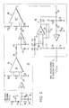
- this amplifier 20 has an impedance converter 83 as an input stage, which serves to adapt the relatively high output resistance of the resonance system 18 to the low input resistance of the subsequent first amplifier stage 84, the output signal of which via a further impedance converter 85 of the second amplifier stage 86 is fed.
- This two-stage structure of the Amplifier 20, in which each of the two stages has a comparatively low gain of approximately 1:10, has the advantage that it exhibits a significantly lower tendency to oscillate than a single-stage amplifier with a corresponding gain of 1: 100.
- the output signal of the second amplifier stage 86 is fed via a galvanically decoupling capacitor 87 to a control circuit 90 which keeps the DC voltage zero level constant at a predetermined value, which has a third impedance converter 91 with associated circuitry in its forward branch and a normal low-drift operational amplifier in its feedback branch 92 includes with appropriate wiring.
- the output DC voltage level thus stabilized against temperature-related fluctuations and due to component aging, to which an amplified, damped, sinusoidal oscillation signal is superimposed whenever the oscillation system 18 has been excited to oscillate by a light pulse received by the photodiode 17. is then fed directly to the circuit arrangement 22 for generating a time-significant signal, the main task of which is to determine the proper oscillation of the resonance system 18 and then to detect a predetermined zero crossing of this oscillation and to use it to generate a time-significant signal.
- integrated circuits are used as the impedance converters 83, 85 and 91, as are sold, for example, by National Semiconductor under the designation LH 0033-CG.
- each amplifier stage 84 or 86 is a programmable amplifier, such as that sold by the company Advanced Micro Devices under the name AM 733-T.
- an operational amplifier 92 is used, which is offered by the company Analog Devices under the name AD 741 LN.
- AD 741 LN Analog Devices
- the output signal of the impedance converter 83 is fed via a coupling capacitor 93 to the first input of the programmable amplifier 95 of the first amplifier stage 84 which is connected to ground via a resistor 94.
- the second input of amplifier 95 is terminated to ground via a resistor 96.
- a program resistor 97 which determines the gain of this amplifier stage, is connected between the programming inputs.
- the output signal of the first amplifier stage 84 is fed via a capacitor 98 and a voltage divider formed by the resistors 101 and 102 to the input of the second impedance converter 85, which is connected to the connection point of the two resistors 101 and 102. Between this point and the ground, a filter capacitor 103 is arranged for switching off RF interference.
- the output signal of the impedance converter 85 is fed via a galvanically isolating coupling capacitor 105 to the one input of the programmable amplifier 107 of the second amplifier stage 86 which is connected to ground via a resistor 106.
- the second input of this programmable amplifier 107 is connected to ground via a resistor 108, while the gain of this amplification stage is predetermined by a programming resistor 109.
- the AC output signal of the second amplifier stage 86 reaches the input of the third impedance converter 91 via the capacitor 87 for galvanic decoupling and a series resistor 110, the input DC voltage of which is roughly determined by a voltage divider, which is formed by the resistors 111 and 112 is formed, which are connected between a supply voltage source and the ground.
- the influencing of the DC input voltage of the impedance converter 91 which serves to keep its DC output voltage constant, takes place with the aid of the output signal of the feedback branch of the control circuit 90, which is fed to the common connection point of the resistors 110, 111 and 112 and the capacitor 87.
- a capacitor 113 which suppresses HF interference is also connected directly between the input of the impedance converter 91 and the ground.
- the output of the impedance converter 91 is connected to ground on the one hand via a resistor 114.
- the DC voltage signal appearing on it is fed via a resistor 115, a choke 116 suppressing AC components and a further resistor 117 to the inverting input of the operational amplifier 92, the non-inverting input of which is formed by means of a voltage divider formed by the resistors 118, 119 and 120 is set to a reference potential, which is kept free of RF interference by a filter capacitor 121.
- the output signal of the operational amplifier 92 is sent to the inverting input of the operational amplifier 92 on the one hand via a feedback branch consisting of a capacitor 125 and a resistor 126 connected in parallel thereto, and on the other hand via a resistor stood 127 on the above-mentioned connection point of the resistors 110, 111, 112 and the capacitor 87.
Claims (3)
- (1)
Applications Claiming Priority (2)
| Application Number | Priority Date | Filing Date | Title |
|---|---|---|---|
| DE3103567 | 1981-02-03 | ||
| DE19813103567 DE3103567A1 (de) | 1981-02-03 | 1981-02-03 | Entfernungsmessverfahren nach dem prinzip der laufzeitmessung eines messlichtimpulses und vorrichtung zu seiner durchfuehrung |
Related Parent Applications (1)
| Application Number | Title | Priority Date | Filing Date |
|---|---|---|---|
| EP82100639.2 Division | 1982-01-29 |
Publications (3)
| Publication Number | Publication Date |
|---|---|
| EP0165403A2 EP0165403A2 (fr) | 1985-12-27 |
| EP0165403A3 EP0165403A3 (en) | 1986-03-19 |
| EP0165403B1 true EP0165403B1 (fr) | 1989-08-16 |
Family
ID=6123924
Family Applications (3)
| Application Number | Title | Priority Date | Filing Date |
|---|---|---|---|
| EP82100639A Expired EP0057447B1 (fr) | 1981-02-03 | 1982-01-29 | Appareil de mesure de distance selon le principe de la mesure de temps de propagation d'une impulsion de lumière |
| EP85104783A Expired EP0166106B1 (fr) | 1981-02-03 | 1982-01-29 | Circuit récepteur pour un appareil de mesure de distance selon le principe de la mesure du temps de propagation d'une impulsion de lumière |
| EP85104782A Expired EP0165403B1 (fr) | 1981-02-03 | 1982-01-29 | Procédé pour commander la dynamique d'un appareil de mesure de distance selon le principe de la mesure du temps de propagation d'une impulsion de lumière et dispositif pour la mise en oeuvre de ce procédé |
Family Applications Before (2)
| Application Number | Title | Priority Date | Filing Date |
|---|---|---|---|
| EP82100639A Expired EP0057447B1 (fr) | 1981-02-03 | 1982-01-29 | Appareil de mesure de distance selon le principe de la mesure de temps de propagation d'une impulsion de lumière |
| EP85104783A Expired EP0166106B1 (fr) | 1981-02-03 | 1982-01-29 | Circuit récepteur pour un appareil de mesure de distance selon le principe de la mesure du temps de propagation d'une impulsion de lumière |
Country Status (5)
| Country | Link |
|---|---|
| US (1) | US4521107A (fr) |
| EP (3) | EP0057447B1 (fr) |
| JP (1) | JPS57147800A (fr) |
| DE (1) | DE3103567A1 (fr) |
| ZA (1) | ZA82223B (fr) |
Families Citing this family (85)
| Publication number | Priority date | Publication date | Assignee | Title |
|---|---|---|---|---|
| US4498764A (en) * | 1981-06-09 | 1985-02-12 | Ludwig Bolkow | Dynamic control arrangement for a distance measuring apparatus |
| DE3219452C2 (de) * | 1981-06-09 | 1986-04-24 | MTC, Meßtechnik und Optoelektronik AG, Neuenburg/Neuchâtel | Dynamik-Steuerungsanordnung für ein Entfernungsmeßgerät |
| DE3216313C2 (de) * | 1982-05-03 | 1994-11-03 | Hipp Johann F | Regelungselektronische Einrichtung für elektrooptische Entfernungsmesser mit Lichtpulslaufzeit-Meßverfahren |
| CH644243B (de) * | 1982-05-06 | Wild Heerbrugg Ag | Vorrichtung zur laufzeitmessung von elektrischen impulssignalen. | |
| DE3411540A1 (de) * | 1984-03-29 | 1985-10-10 | Fried. Krupp Gmbh, 4300 Essen | Verfahren und vorrichtung zur ermittlung des foerdergutmengenstromes von bandfoerderern |
| DE3419117C2 (de) * | 1984-05-23 | 1986-09-04 | Rheometron AG, Basel | Optoelektrisches Entfernungsmeßgerät mit einem Zeitdiskriminator zur genauen Ermittlung der Zeitfolge elektrischer Impulse |
| DE3425098C2 (de) * | 1984-07-07 | 1986-11-06 | Messerschmitt-Bölkow-Blohm GmbH, 8012 Ottobrunn | Einrichtung zum Erfassen, Abstandsmessen und Abbilden von Objekten in umhüllenden trüben Medien mittels Laser |
| DE3540157A1 (de) * | 1985-11-13 | 1987-05-21 | Messerschmitt Boelkow Blohm | Verfahren und vorrichtung zur entfernungsmessung |
| CH670896A5 (fr) * | 1986-08-13 | 1989-07-14 | Zellweger Uster Ag | |
| FR2608284B1 (fr) * | 1986-12-16 | 1989-03-31 | Thomson Csf | Telemetre optique a illuminateur coherent, insensible aux vibrations et aux variations thermiques |
| DE3703772A1 (de) * | 1987-02-07 | 1988-08-25 | Messerschmitt Boelkow Blohm | Synchronisationseinrichtung in einem optoelektronischen entfernungsmesssystem |
| US4875770A (en) * | 1987-03-23 | 1989-10-24 | Lockheed Corporation | Wind shear detector |
| DE3764362D1 (de) * | 1987-03-26 | 1990-09-20 | Messerschmitt Boelkow Blohm | Detektorvorrichtung. |
| US4859054A (en) * | 1987-07-10 | 1989-08-22 | The United States Of America As Represented By The United States Department Of Energy | Proximity fuze |
| WO1989007771A1 (fr) * | 1988-02-10 | 1989-08-24 | Messerschmitt-Bölkow-Blohm Gesellschaft Mit Beschr | Appareil optique de mesure de distance |
| DE3810512A1 (de) * | 1988-03-28 | 1989-10-12 | Johann Hipp | Verfahren und vorrichtung zur entfernungsmessung mit schwachen laserlichtpulsen |
| US5013917A (en) * | 1988-07-07 | 1991-05-07 | Kaman Aerospace Corporation | Imaging lidar system using non-visible light |
| JPH03189584A (ja) * | 1989-12-19 | 1991-08-19 | Omron Corp | 距離測定装置 |
| DE4002356C2 (de) * | 1990-01-26 | 1996-10-17 | Sick Optik Elektronik Erwin | Abstandsmeßgerät |
| US5050986A (en) * | 1990-06-05 | 1991-09-24 | Motorola, Inc. | Synchronization system for controlling switches |
| DE4026956A1 (de) * | 1990-08-25 | 1992-03-05 | Daimler Benz Ag | Videokamera |
| FR2678071B1 (fr) * | 1991-06-18 | 1994-11-04 | Thomson Csf | Dispositif electronique de mesure de retards. |
| GB2272123B (en) * | 1992-11-03 | 1996-08-07 | Marconi Gec Ltd | Laser radar system |
| DE4304290C1 (de) * | 1993-02-12 | 1994-03-03 | Sick Optik Elektronik Erwin | Vorrichtung zur Messung der Laufzeit von elektromagnetischen Wellen |
| DE4318623A1 (de) * | 1993-06-04 | 1994-12-08 | Ifm Electronic Gmbh | Entfernungsmeßgerät nach dem Laufzeitprinzip |
| DE4419472C2 (de) * | 1993-06-04 | 2002-03-28 | Ifm Electronic Gmbh | Entfernungsmeßgerät nach dem Laufzeitprinzip |
| JP3120202B2 (ja) * | 1993-11-18 | 2000-12-25 | 株式会社トプコン | パルス方式の光波距離計 |
| DE4411218C1 (de) * | 1994-02-25 | 1995-09-07 | Rudolf Prof Dr Ing Schwarte | Entfernungsmeßgerät nach dem Laufzeitprinzip |
| US6023323A (en) * | 1994-10-20 | 2000-02-08 | Nissan Motor Co., Ltd. | Laser beam type distance measuring device |
| JPH1062549A (ja) * | 1996-08-15 | 1998-03-06 | Nikon Corp | 距離測定装置 |
| US5790244A (en) * | 1996-08-23 | 1998-08-04 | Laser Technology, Inc. | Pre-biasing technique for a transistor based avalanche circuit in a laser based distance measurement and ranging instrument |
| DE19704340A1 (de) * | 1997-02-05 | 1998-08-06 | Sick Ag | Entfernungsmesser |
| JPH10227857A (ja) * | 1997-02-14 | 1998-08-25 | Nikon Corp | 光波測距装置 |
| US5852410A (en) * | 1997-03-04 | 1998-12-22 | Maxtec International Corporation | Laser optical path degradation detecting device |
| JPH1123709A (ja) * | 1997-07-07 | 1999-01-29 | Nikon Corp | 距離測定装置 |
| US6363036B1 (en) | 1998-12-31 | 2002-03-26 | Lighttime, L.L.C. | Light clock |
| DE10025594A1 (de) * | 2000-05-24 | 2001-11-29 | Diehl Munitionssysteme Gmbh | Empfindlichkeitsabgleichung eines optronischen Zünders |
| DE10027239A1 (de) | 2000-05-31 | 2001-12-06 | Sick Ag | Verfahren zur Abstandsmessung und Abstandsmeßeinrichtung |
| US6469777B2 (en) * | 2000-06-12 | 2002-10-22 | Asahi Kogaku Kogyo Kabushiki Kaisha | Surveying instrument having an optical distance meter |
| EP1176430B1 (fr) | 2000-07-27 | 2008-09-10 | Leuze electronic GmbH + Co. KG | Dispositif optoélectronique |
| DE10112833C1 (de) * | 2001-03-16 | 2003-03-13 | Hilti Ag | Verfahren und Einrichtung zur elektrooptischen Distanzmessung |
| EP1251363B1 (fr) * | 2001-04-20 | 2005-04-27 | Krohne Messtechnik Gmbh & Co. Kg | Procédé de traitement d'un signal de fréquence |
| DE10163925A1 (de) * | 2001-12-22 | 2003-07-03 | Conti Temic Microelectronic | Verfahren zur Abstandsmessung |
| AT412029B (de) * | 2002-01-16 | 2004-08-26 | Riegl Laser Measurement Sys | Verfahren zur aufnahme eines objektraumes |
| FI20020279A0 (fi) * | 2002-02-12 | 2002-02-12 | Juha Tapio Kostamovaara | Menetelmä ja järjestely liipaisun ja liipaisun ajoituksen suorittamiseksi |
| EP1499851A4 (fr) * | 2002-04-15 | 2008-11-19 | Toolz Ltd | Dispositif de mesure de distance |
| US6829042B1 (en) * | 2002-06-10 | 2004-12-07 | Matsushita Electric Works, Ltd. | Distance measuring apparatus and method using a pulsed electromagnetic wave |
| US6803998B2 (en) * | 2002-08-20 | 2004-10-12 | Applied Materials, Inc. | Ultra low cost position and status monitoring using fiber optic delay lines |
| WO2005092071A2 (fr) * | 2004-03-24 | 2005-10-06 | General Dynamic Advanced Information Systems, Inc. | Procede et systeme de telemetrie de photons enchevetres |
| US7362420B2 (en) * | 2004-03-24 | 2008-04-22 | General Dynamics Advanced Information Systems, Inc. | Entangled-photons range finding system and method |
| US7030365B2 (en) * | 2004-04-15 | 2006-04-18 | Eaton Corporation | Emitter-detector assembly for a reflex photoelectric object detection system |
| US7714990B2 (en) * | 2004-12-16 | 2010-05-11 | Hilti Aktiengesellschaft | Hand-held laser distance measuring device with a pulse reflection mixing method |
| DE102004060619A1 (de) | 2004-12-16 | 2006-07-06 | Hilti Ag | Laserdistanzhandmessgerät mit einem Impulsrückmischverfahren |
| DE102004060622B4 (de) | 2004-12-16 | 2015-01-22 | Hilti Aktiengesellschaft | Impuls-Laserdistanzhandmessgerät |
| US7345744B2 (en) * | 2005-06-06 | 2008-03-18 | Raytheon Company | Optical delay line to correct phase errors in coherent ladar |
| EP1752788A1 (fr) * | 2005-08-08 | 2007-02-14 | Leica Geosystems AG | Télémètre électro-optique |
| US7983548B2 (en) * | 2005-10-28 | 2011-07-19 | Hewlett-Packard Development Company, L.P. | Systems and methods of generating Z-buffers in cameras |
| US8391698B2 (en) * | 2005-10-28 | 2013-03-05 | Hewlett-Packard Development Company, L.P. | Systems and methods of generating Z-buffers for an image capture device of a camera |
| US7511800B2 (en) * | 2005-11-28 | 2009-03-31 | Robert Bosch Company Limited | Distance measurement device with short range optics |
| DE102006036166A1 (de) * | 2006-03-20 | 2007-10-04 | Micro-Epsilon Optronic Gmbh | Vorrichtung und Verfahren zur Messung der Entfernung eines Objekts |
| JP5469793B2 (ja) * | 2006-09-20 | 2014-04-16 | 株式会社トプコン | 距離測定装置 |
| DE102006060108A1 (de) | 2006-12-20 | 2008-06-26 | Sick Ag | Laserscanner |
| WO2012141810A1 (fr) | 2011-03-03 | 2012-10-18 | Faro Technologies, Inc. | Appareil et procédé pour cible |
| US9482755B2 (en) | 2008-11-17 | 2016-11-01 | Faro Technologies, Inc. | Measurement system having air temperature compensation between a target and a laser tracker |
| JP5683782B2 (ja) * | 2008-12-25 | 2015-03-11 | 株式会社トプコン | 距離測定装置及び距離測定方法 |
| US8659749B2 (en) * | 2009-08-07 | 2014-02-25 | Faro Technologies, Inc. | Absolute distance meter with optical switch |
| US9400170B2 (en) | 2010-04-21 | 2016-07-26 | Faro Technologies, Inc. | Automatic measurement of dimensional data within an acceptance region by a laser tracker |
| US9377885B2 (en) | 2010-04-21 | 2016-06-28 | Faro Technologies, Inc. | Method and apparatus for locking onto a retroreflector with a laser tracker |
| US8619265B2 (en) | 2011-03-14 | 2013-12-31 | Faro Technologies, Inc. | Automatic measurement of dimensional data with a laser tracker |
| US9772394B2 (en) | 2010-04-21 | 2017-09-26 | Faro Technologies, Inc. | Method and apparatus for following an operator and locking onto a retroreflector with a laser tracker |
| US8902408B2 (en) | 2011-02-14 | 2014-12-02 | Faro Technologies Inc. | Laser tracker used with six degree-of-freedom probe having separable spherical retroreflector |
| USD688577S1 (en) | 2012-02-21 | 2013-08-27 | Faro Technologies, Inc. | Laser tracker |
| US9164173B2 (en) | 2011-04-15 | 2015-10-20 | Faro Technologies, Inc. | Laser tracker that uses a fiber-optic coupler and an achromatic launch to align and collimate two wavelengths of light |
| US9686532B2 (en) | 2011-04-15 | 2017-06-20 | Faro Technologies, Inc. | System and method of acquiring three-dimensional coordinates using multiple coordinate measurement devices |
| US9482529B2 (en) | 2011-04-15 | 2016-11-01 | Faro Technologies, Inc. | Three-dimensional coordinate scanner and method of operation |
| JP2014516409A (ja) | 2011-04-15 | 2014-07-10 | ファロ テクノロジーズ インコーポレーテッド | レーザトラッカの改良位置検出器 |
| JP6099675B2 (ja) | 2012-01-27 | 2017-03-22 | ファロ テクノロジーズ インコーポレーテッド | バーコード識別による検査方法 |
| US9470520B2 (en) * | 2013-03-14 | 2016-10-18 | Apparate International C.V. | LiDAR scanner |
| US9041914B2 (en) | 2013-03-15 | 2015-05-26 | Faro Technologies, Inc. | Three-dimensional coordinate scanner and method of operation |
| US9395174B2 (en) | 2014-06-27 | 2016-07-19 | Faro Technologies, Inc. | Determining retroreflector orientation by optimizing spatial fit |
| DE102017101501B3 (de) * | 2017-01-26 | 2018-01-04 | Sick Ag | Optoelektronischer Sensor und Verfahren zur Bestimmung der Entfernung eines Objekts in einem Überwachungsbereich |
| US11428790B2 (en) * | 2017-06-05 | 2022-08-30 | Texas Instruments Incorporated | Narrowband TIA and signaling for optical distance measurement systems |
| US10340651B1 (en) * | 2018-08-21 | 2019-07-02 | Luminar Technologies, Inc. | Lidar system with optical trigger |
| CN113238246A (zh) * | 2021-05-06 | 2021-08-10 | 武汉科技大学 | 基于脉冲序列的距离速度同时测量方法及装置及存储介质 |
| CN114706058B (zh) * | 2022-03-09 | 2024-04-09 | 深圳市速腾聚创科技有限公司 | 一种激光接收系统以及激光测距系统 |
Family Cites Families (18)
| Publication number | Priority date | Publication date | Assignee | Title |
|---|---|---|---|---|
| US3390348A (en) * | 1966-04-28 | 1968-06-25 | Aga Ab | System for generating a signal representing the time delay of a signal patch |
| NO128351B (fr) * | 1967-10-18 | 1973-10-29 | Krupp Gmbh | |
| US3743419A (en) * | 1969-07-09 | 1973-07-03 | Bofors Ab | Ranging system |
| US3619058A (en) * | 1969-11-24 | 1971-11-09 | Hewlett Packard Co | Distance measuring apparatus |
| SE337486B (fr) * | 1969-11-27 | 1971-08-09 | Aga Ab | |
| US3779645A (en) * | 1970-05-20 | 1973-12-18 | Nippon Kogaku Kk | Distance measuring device |
| US3752582A (en) * | 1971-01-27 | 1973-08-14 | Bendix Corp | Optical range and range-rate sensor |
| US3740141A (en) * | 1971-09-20 | 1973-06-19 | Laser Systems & Electronics | Timing and measuring methods and means for laser distance measurements |
| SE358243B (fr) * | 1971-11-25 | 1973-07-23 | Aga Ab | |
| US3900261A (en) * | 1974-03-18 | 1975-08-19 | Transitek Corp | Electronic range finder |
| US3992615A (en) * | 1975-05-14 | 1976-11-16 | Sun Studs, Inc. | Electro-optical ranging system for distance measurements to moving targets |
| US4181431A (en) * | 1976-07-31 | 1980-01-01 | Mitec-Moderne Industrietechnik Gmbh | Laser distance measuring apparatus |
| DE2634627C2 (de) * | 1976-07-31 | 1982-08-19 | MITEC Moderne Industrietechnik GmbH, 8012 Ottobrunn | Laserentfernungsmeßgerät |
| US4113381A (en) * | 1976-11-18 | 1978-09-12 | Hewlett-Packard Company | Surveying instrument and method |
| CH611039A5 (en) * | 1977-01-21 | 1979-05-15 | Eidgenoess Mil Dept | Distance meter |
| DE2723835C2 (de) * | 1977-05-26 | 1982-09-23 | MITEC Moderne Industrietechnik GmbH, 8012 Ottobrunn | Laserentfernungsmeßgerät nach dem Prinzip der Laufzeitmessung eines Lichtimpulses |
| CH641279A5 (de) * | 1979-07-13 | 1984-02-15 | Kern & Co Ag | Verfahren zur messung der entfernung zwischen einem objekt und einem bezugspunkt, sowie vorrichtung zu dessen durchfuehrung. |
| DE3020996C2 (de) * | 1980-06-03 | 1989-07-20 | Messerschmitt-Bölkow-Blohm GmbH, 8012 Ottobrunn | Einrichtung zur Bestimmung der Auslöseentfernung von einem sich auf ein Ziel zu bewegenden Flugkörper |
-
1981
- 1981-02-03 DE DE19813103567 patent/DE3103567A1/de active Granted
-
1982
- 1982-01-13 ZA ZA82223A patent/ZA82223B/xx unknown
- 1982-01-29 EP EP82100639A patent/EP0057447B1/fr not_active Expired
- 1982-01-29 EP EP85104783A patent/EP0166106B1/fr not_active Expired
- 1982-01-29 EP EP85104782A patent/EP0165403B1/fr not_active Expired
- 1982-02-03 JP JP57014997A patent/JPS57147800A/ja active Pending
-
1984
- 1984-09-26 US US06/654,807 patent/US4521107A/en not_active Expired - Fee Related
Also Published As
| Publication number | Publication date |
|---|---|
| DE3103567C2 (fr) | 1988-10-20 |
| EP0165403A2 (fr) | 1985-12-27 |
| JPS57147800A (en) | 1982-09-11 |
| EP0057447A1 (fr) | 1982-08-11 |
| US4521107A (en) | 1985-06-04 |
| EP0165403A3 (en) | 1986-03-19 |
| EP0057447B1 (fr) | 1986-10-08 |
| EP0166106A1 (fr) | 1986-01-02 |
| DE3103567A1 (de) | 1982-08-12 |
| EP0166106B1 (fr) | 1989-01-04 |
| ZA82223B (en) | 1982-11-24 |
Similar Documents
| Publication | Publication Date | Title |
|---|---|---|
| EP0165403B1 (fr) | Procédé pour commander la dynamique d'un appareil de mesure de distance selon le principe de la mesure du temps de propagation d'une impulsion de lumière et dispositif pour la mise en oeuvre de ce procédé | |
| EP0066889B1 (fr) | Dispositif de commande de la dynamique pour un appareil de mesure de distance | |
| DE2216765C3 (de) | Verfahren und Einrichtung zur Entfernungsmessung | |
| EP1936400B1 (fr) | Lecteur laser | |
| EP0439011B1 (fr) | Télémètre | |
| EP1423731B1 (fr) | Procede et dispositif pour acquerir une image telemetrique tridimensionnelle | |
| EP2189805B1 (fr) | Capteur optoélectronique et procédé destiné à la mesure de distance selon le principe du temps de propagation de la lumière | |
| EP1972961B1 (fr) | Capteur optoélectronique et procédé de mesure de l'éloignement ou de la modification de l'éloignement | |
| EP2189814B1 (fr) | Capteur optoélectronique et procédé destiné à la mesure d'éloignements selon le principe du temps de propagation de la lumière | |
| EP0742450B1 (fr) | Procédé et dispositif de mesure du temps de vol de lumière le long d'une trajectoire de mesure entre un dispositif de mesure et un objet réfléchissant | |
| DE60225430T2 (de) | Entfernungsfinder, entfernungsfindeverfahren und photoelektrische wandlerschaltung | |
| DE3210237A1 (de) | Laser-entfernungsmesser | |
| DE19757834B4 (de) | Verfahren zum Reduzieren des Rauschens im Empfänger eines Laser-Entfernungsmeßgeräts | |
| DE2452794A1 (de) | Schaltungsanordnung zur automatischen pegeleinstellung fuer optische sensoren mit gepulster strahlung, z.b. fuer ueberwachungsgeraete | |
| EP1990657A1 (fr) | Appareil de mesure de distances optique | |
| DE3216313C2 (de) | Regelungselektronische Einrichtung für elektrooptische Entfernungsmesser mit Lichtpulslaufzeit-Meßverfahren | |
| DE10232878A1 (de) | Vorrichtung und Verfahren zur Distanzmessung | |
| DE2530874A1 (de) | Verfahren und einrichtung zur fokussierung eines optischen systems | |
| WO1988005922A1 (fr) | Procede et installation pour mesurer une distance par le traitement d'un signal optique a impulsions | |
| DE4304290C1 (de) | Vorrichtung zur Messung der Laufzeit von elektromagnetischen Wellen | |
| DE3219452C2 (de) | Dynamik-Steuerungsanordnung für ein Entfernungsmeßgerät | |
| DE10153742A1 (de) | Verfahren und Vorrichtung zur Aufnahme eines dreidimensionalen Abstandsbildes | |
| DE3022857A1 (de) | Einrichtung zur laufzeitmessung | |
| DE10018948B4 (de) | Optoelektronische Vorrichtung | |
| DE4421092C2 (de) | Entfernungsmeßeinrichtung für eine Kamera |
Legal Events
| Date | Code | Title | Description |
|---|---|---|---|
| PUAI | Public reference made under article 153(3) epc to a published international application that has entered the european phase |
Free format text: ORIGINAL CODE: 0009012 |
|
| AC | Divisional application: reference to earlier application |
Ref document number: 57447 Country of ref document: EP |
|
| AK | Designated contracting states |
Designated state(s): CH FR GB LI NL SE |
|
| PUAL | Search report despatched |
Free format text: ORIGINAL CODE: 0009013 |
|
| AK | Designated contracting states |
Kind code of ref document: A3 Designated state(s): CH FR GB LI NL SE |
|
| 17P | Request for examination filed |
Effective date: 19860430 |
|
| 17Q | First examination report despatched |
Effective date: 19870904 |
|
| RAP1 | Party data changed (applicant data changed or rights of an application transferred) |
Owner name: MITEC MIKROELEKTRONIK MIKROTECHNIK INFORMATIK GMBH |
|
| GRAA | (expected) grant |
Free format text: ORIGINAL CODE: 0009210 |
|
| AC | Divisional application: reference to earlier application |
Ref document number: 57447 Country of ref document: EP |
|
| AK | Designated contracting states |
Kind code of ref document: B1 Designated state(s): CH FR GB LI NL SE |
|
| PG25 | Lapsed in a contracting state [announced via postgrant information from national office to epo] |
Ref country code: SE Effective date: 19890816 Ref country code: NL Effective date: 19890816 |
|
| GBT | Gb: translation of ep patent filed (gb section 77(6)(a)/1977) | ||
| ET | Fr: translation filed | ||
| NLV1 | Nl: lapsed or annulled due to failure to fulfill the requirements of art. 29p and 29m of the patents act | ||
| RAP2 | Party data changed (patent owner data changed or rights of a patent transferred) |
Owner name: MITEC MIKROELEKTRONIK MIKROTECHNIK INFORMATIK GMBH |
|
| PLBE | No opposition filed within time limit |
Free format text: ORIGINAL CODE: 0009261 |
|
| STAA | Information on the status of an ep patent application or granted ep patent |
Free format text: STATUS: NO OPPOSITION FILED WITHIN TIME LIMIT |
|
| 26N | No opposition filed | ||
| REG | Reference to a national code |
Ref country code: CH Ref legal event code: PUE Owner name: BAYERISCHE MOTOREN WERKE AKTIENGESELLSCHAFT |
|
| REG | Reference to a national code |
Ref country code: GB Ref legal event code: 732 |
|
| REG | Reference to a national code |
Ref country code: FR Ref legal event code: TP |
|
| PGFP | Annual fee paid to national office [announced via postgrant information from national office to epo] |
Ref country code: FR Payment date: 19921230 Year of fee payment: 12 |
|
| PGFP | Annual fee paid to national office [announced via postgrant information from national office to epo] |
Ref country code: GB Payment date: 19930111 Year of fee payment: 12 |
|
| PGFP | Annual fee paid to national office [announced via postgrant information from national office to epo] |
Ref country code: CH Payment date: 19930123 Year of fee payment: 12 |
|
| PG25 | Lapsed in a contracting state [announced via postgrant information from national office to epo] |
Ref country code: GB Effective date: 19940129 |
|
| PG25 | Lapsed in a contracting state [announced via postgrant information from national office to epo] |
Ref country code: LI Effective date: 19940131 Ref country code: CH Effective date: 19940131 |
|
| GBPC | Gb: european patent ceased through non-payment of renewal fee |
Effective date: 19940129 |
|
| PG25 | Lapsed in a contracting state [announced via postgrant information from national office to epo] |
Ref country code: FR Effective date: 19940930 |
|
| REG | Reference to a national code |
Ref country code: CH Ref legal event code: PL |
|
| REG | Reference to a national code |
Ref country code: FR Ref legal event code: ST |