EP0165403B1 - Method for controlling the dynamics of a distance-measuring apparatus according to the principles of measurement of the transition time of light pulses, and apparatus for carrying out the method - Google Patents
Method for controlling the dynamics of a distance-measuring apparatus according to the principles of measurement of the transition time of light pulses, and apparatus for carrying out the method Download PDFInfo
- Publication number
- EP0165403B1 EP0165403B1 EP85104782A EP85104782A EP0165403B1 EP 0165403 B1 EP0165403 B1 EP 0165403B1 EP 85104782 A EP85104782 A EP 85104782A EP 85104782 A EP85104782 A EP 85104782A EP 0165403 B1 EP0165403 B1 EP 0165403B1
- Authority
- EP
- European Patent Office
- Prior art keywords
- amplifier
- measurement
- light pulse
- signal
- time
- Prior art date
- Legal status (The legal status is an assumption and is not a legal conclusion. Google has not performed a legal analysis and makes no representation as to the accuracy of the status listed.)
- Expired
Links
Images

Classifications
-
- G—PHYSICS
- G01—MEASURING; TESTING
- G01S—RADIO DIRECTION-FINDING; RADIO NAVIGATION; DETERMINING DISTANCE OR VELOCITY BY USE OF RADIO WAVES; LOCATING OR PRESENCE-DETECTING BY USE OF THE REFLECTION OR RERADIATION OF RADIO WAVES; ANALOGOUS ARRANGEMENTS USING OTHER WAVES
- G01S7/00—Details of systems according to groups G01S13/00, G01S15/00, G01S17/00
- G01S7/48—Details of systems according to groups G01S13/00, G01S15/00, G01S17/00 of systems according to group G01S17/00
- G01S7/481—Constructional features, e.g. arrangements of optical elements
- G01S7/4818—Constructional features, e.g. arrangements of optical elements using optical fibres
-
- G—PHYSICS
- G01—MEASURING; TESTING
- G01S—RADIO DIRECTION-FINDING; RADIO NAVIGATION; DETERMINING DISTANCE OR VELOCITY BY USE OF RADIO WAVES; LOCATING OR PRESENCE-DETECTING BY USE OF THE REFLECTION OR RERADIATION OF RADIO WAVES; ANALOGOUS ARRANGEMENTS USING OTHER WAVES
- G01S17/00—Systems using the reflection or reradiation of electromagnetic waves other than radio waves, e.g. lidar systems
- G01S17/02—Systems using the reflection of electromagnetic waves other than radio waves
- G01S17/06—Systems determining position data of a target
- G01S17/08—Systems determining position data of a target for measuring distance only
- G01S17/10—Systems determining position data of a target for measuring distance only using transmission of interrupted, pulse-modulated waves
- G01S17/14—Systems determining position data of a target for measuring distance only using transmission of interrupted, pulse-modulated waves wherein a voltage or current pulse is initiated and terminated in accordance with the pulse transmission and echo reception respectively, e.g. using counters
Definitions
- the invention relates to a method and a device for controlling the dynamics of a distance measuring device according to the principle of light pulse transit time measurement with the features mentioned in the preamble of claim 1 and claim 2, respectively.
- the resonance system is triggered by a very bright light pulse to a vibration so strong that the amplifier connected to it is overdriven, the resonance system in a target object located very close to and / or very strongly reflecting can be overdriven, so that there can be considerable time shifts in the zero crossings of the amplifier. Output signal coming.
- DE-A 2723835 describes a method of the type mentioned at the beginning and an apparatus for carrying out this method.
- the resonance system of the receiving channel is followed by an amplifier with a controllable gain factor, the output signal of which is compared by a comparator with a predetermined reference voltage. If the amplitude of the amplifier output signal exceeds the reference voltage, the comparator generates a signal which, on the one hand, leads to the current measurement being aborted or the measurement value obtained not being used and, on the other hand, the gain factor of the amplifier connected downstream of the resonance system being reduced. The measurement attempt is then repeated with this reduced amplification factor in that a new light pulse is emitted. This process is repeated until the amplitude of the amplifier output signal no longer exceeds the reference voltage and thus an accurate transit time measurement is ensured.
- US-A 3900261 also shows a distance measuring device based on the principle of light pulse transit time measurement, in which the gain of an amplifier connected downstream of the electro-optical receiver is automatically regulated in order to avoid overdriving.
- the use of a resonance system and a comparison of the amplitude of an oscillation signal emitted by the amplifier with a reference voltage for detecting the overload is not described there.
- the known change in the amplification factor of an amplifier in the reception channel of a distance measuring device for controlling the dynamics i.e. for adapting to target objects at different distances and / or reflecting at different intensities, however, has the disadvantage that it can only be used to sweep over a very small dynamic range, which is at most of the order of 1: 100.
- a small dynamic range means that the distance measuring range of such a measuring device is very limited, because the brightness of the measuring light pulses must be chosen so small that the amplifier in the receiving channel is not overdriven even when the target objects are very close and strongly reflecting.
- the maximum range of such a distance measuring device is very small.
- the invention has for its object to provide a method and an apparatus of the type mentioned, which make it possible to cover an extremely large dynamic range for measuring the distance of both near and very distant target objects for all these measurements to achieve high measuring accuracy.
- the invention provides the features set out in claim 1.
- a device suitable for carrying out a method according to the invention is set out in claim 2.
- the amplifier can be set to a gain factor in which there is no tendency to oscillate.
- the amplifier output signal represents an exact reproduction of the oscillation signal supplied to the amplifier, and its zero crossings have an exact time correlation at the time of reception of the respective light pulse, which is reproducible in the required manner; Therefore, this amplifier output signal is also suitable for generating a time-significant signal, even with very high demands on the measurement accuracy.
- device parameters are changed according to the invention which influence the amplitude of the oscillation signal supplied to the amplifier.
- These include, in particular, the sensitivity of the electro-optical receiver, which can be influenced by changing its bias voltage, and the brightness of the light pulses arriving at the electro-optical receiver, which in turn by controlling the transmitter power and / or by changing the attenuation factor of a controllable attenuator arranged in the measurement light path can be changed.
- a step-by-step approach to the correct damping value takes place.
- a first measurement attempt is made in which all device parameters influencing the amplitude of the vibration signal supplied to the amplifier are switched to values such that this amplitude becomes as large as possible for a given distance and given reflectivity of the target object.
- a first measurement attempt is made in which a measurement light pulse is transmitted and received. If the comparison of the amplifier output signal with the reference voltage indicates that the amplifier is operating in the linear range, the measurement result is recorded and evaluated by the measuring device.
- the first measurement attempt is rejected and at least one of the available device parameters is switched over to another value to carry out a second measurement attempt, which leads to damping, i.e. leads to a reduction in the amplitude of the oscillation signal supplied to the amplifier. Since the first measurement attempt, which failed due to the amplifier being overdriven, only the fact and not the extent of the overdrive is ascertained, it is not known which damping factor must be selected in order to reach the linearity range of the amplifier.
- a basic attenuation value is first switched on, which according to the invention is selected so that it is somewhat smaller than the dynamic range of the amplifier, i.e. is smaller than the ratio of the smallest signal amplitude that can just be processed perfectly by the amplifier to the upper limit of the linearity range of the amplifier. This prevents a signal, by which the amplifier was only slightly overdriven during the first measurement attempt, from being attenuated so strongly during the second measurement attempt that it can no longer be evaluated because of its now too small amplitude.
- the second measurement attempt also leads to the amplifier being overdriven, further measurement attempts with increased damping values are necessary.
- the increased damping values available by switching the device parameters to other values are staggered in such a way that they are as close as possible below continuous integer powers of the basic damping value and certainly do not exceed them.
- the basic damping value is set to G, a third attempt can be made with an attenuation value G 2 and, if overdriving occurs, a fourth measurement attempt with an attenuation value G 3 etc. if overdriving occurs. without the risk that the vibration signal supplied to the amplifier is damped too much.
- a distance measuring device operating according to the method according to the invention has a transmitter 1, which comprises, for example, a laser transmission diode 3 and a circuit arrangement 4 which serves to control the transmission diode 3.
- the circuit arrangement 4 essentially consists of a “slowly” rechargeable energy store, for example in the form of a capacitance, and a controllable electronic switch which serves to quickly discharge the energy accumulated in the energy store via the transmitter diode 3, whereupon the transmitter diode 3 emits of a laser light pulse reacts.
- This electronic switch can be controlled for periodic operation with the aid of an oscillator 6 which oscillates at a predetermined frequency.
- the controllable electronic switch for triggering individual pulses is triggered by a central sequence control 10 via a control power 8.
- a first part of each light pulse generated by the transmitter diode 3 is used as a measurement light pulse, i.e. it is sent via an optical fiber 11 and a transmission optics 12, which is shown schematically in simplified form in FIG. 1 as a single lens, to the target object whose distance is to be measured.
- each light pulse generated by the transmitter diode 3 is used as a reference light pulse, i.e. it is decoupled from the transmission optical fiber 11 by a Y-shaped branch 24 and fed into a reference light path, which initially comprises an optical fiber coil 25 and behind this a further Y-shaped branch 26, behind which the reference light path functions in two relative to one another parallel sections 27 and 34 are divided with different lengths.
- a reference light pulse which initially comprises an optical fiber coil 25 and behind this a further Y-shaped branch 26, behind which the reference light path functions in two relative to one another parallel sections 27 and 34 are divided with different lengths.
- These two sections combine at an optical switch 38 into a single light path 28, which leads to a photodiode 17, which forms the electro-optical receiver of the receiving channel 16.
- each reference light pulse is split again into two parts, one of which continues along the short section 27 and the other along the long section 34.
- the optical switch 38 which is actuated via a line 31 from the central sequencer 10
- only one or the other of these two parts of each reference light pulse can reach the photodiode 17 via the light path 28, while the other part is suppressed.
- the optical switch 38 In the case of a target object which is at a sufficiently large distance, the optical switch 38 is in a position in which it connects the short section 27 of the reference light path to the light path 28, so that a reference light pulse which is at the junction 24 of one of the Transmitted diode 3 generated light pulse was branched off, first arrives at the photodiode 17. That part of the associated measuring light pulse which reflects from the target object to the measuring device and is fed into a light path 15 with the aid of a receiving optic 14, again simplified as a single lens, which likewise leads to the photodiode 17, arrives in this case after the reference light pulse at the photodiode 17 .
- this resonance system 18 can also be formed by a series resonant circuit or another electromagnetic oscillation system.
- the resonance system 18 is excited by the signal emitted by the photodiode 17 when each light pulse is received to produce a damped oscillation process which is generally sinusoidal and runs with an exponentially decreasing amplitude of the individual half-oscillations. If the distance of the target object is large, then the time interval between the two light pulses is also large and the first oscillation process, which is triggered by the reception of the reference light pulse, has completely subsided when the measurement light pulse arrives at the photodiode 17 and triggers the second oscillation process.
- the signal emitted by the resonance system 18 in each of these oscillation processes is amplified by a downstream amplifier 20 (see FIG. 2) and then fed to a circuit arrangement 22 which serves to generate a time-significant signal.
- the main task of this circuit arrangement 22 is, whenever a light pulse has been received by the photodiode 17, a time-significant signal, i.e. generate a signal, the temporal position of which is correlated in a precisely defined manner with the temporal focus of the light pulse in question.
- This time-significant signal can be, for example, a falling or rising pulse edge. It follows from the above that for each pair of measurement and reference light pulses that arrive successively at the photodiode 17, two time-significant signals are generated that also occur successively. The time-significant signal that occurs first is always used to start the transit time measurement of the measurement light pulse in question, while the second is used to end this transit time measurement. In the case considered here, in which the measuring light pulse from a target object with a large Distance is reflected, the time-significant signal corresponding to the reference light pulse is first generated, which thus serves as a start signal for the transit time measurement. The time-significant signal corresponding to the measurement light pulse is generated somewhat later and is therefore used to end the runtime measurement.
- the two time-significant signals are fed via a line 23 to a time measuring device which, since it is not the subject of the present invention, has been included in the central sequence control 10 for the sake of simplicity.
- optical fiber coil 25 arranged behind the Y-shaped junction 24 is that the reference light pulse supplied to the receiving channel 16 via the short section 27 of the reference light path has inevitably already decayed with the interference generated.
- the circuit arrangement 22 is blocked immediately after it has recognized that the resonance system 18 is starting to vibrate properly, thereby triggering the generation of a time-significant signal, for a minimum period of time which is somewhat longer than the free time of the reception channel 16, i.e. somewhat longer than the period of time that must elapse before the resonance system 18 can be properly started a second time after a previous initiation.
- the circuit arrangement 22 receives a reset or preparation signal from the sequence controller 10 via the line 29, which signal makes it susceptible again to oscillation processes of the resonance system 18.
- the resonance system 18 initially vibrates and in response to this, the circuit arrangement 22 also generates a first time-significant signal, and thus the time-of-flight measurement.
- the later of the two light pulses arrives at the receiving photodiode 17 at a point in time at which the circuit arrangement 22 has not yet been released again, no second time-significant signal which continues the runtime measurement is generated.
- the ongoing running time measurement very quickly reaches a value linked to this maximum measuring range via the speed of light, the exceeding of which is recognized by the sequence control 10 and as an occasion for canceling the relevant running time measurement and for triggering further control commands is taken.
- One of these control commands which is reproduced via a line 31 to the optical changeover switch 38, causes the latter to connect the long section 34 of the reference light path to the light path 28 leading to the photodiode 17 instead of the short section 27, thereby simultaneously emitting a measuring light pulse reference light pulse emitted by the transmitter diode 3 is delayed more than at least twice the above-mentioned release time T than when passing through the shorter section 27.
- the reference light pulse on the receiving diode 17 always has the same intensity, regardless of whether it was guided over the short or the long section of the reference light path, in the short section 27 there is an attenuator 39 with a fixed one, which is caused by the long section 34 Damping corresponding damping value inserted.
- the sequence control 10 when the switch 38 is in a position in which the reference light pulse running over the short section 27 of the reference light path reaches the receiving channel 16, the sequence control 10 has determined that a runtime measurement has started, but not within a reasonable period of time stopped, she interprets this as a very short distance between the measuring device and the target object and, in response, causes the changeover switch 38 to change over to the other position, in which the reference light pulse running over the long section 34 is fed to the photodiode 17.
- the measurement light pulse reflected at a target object that is only a short distance from the measuring device will reach the receiving diode 17 with certainty at an early stage before the reference light pulse delayed by the long section 34, that both light pulses can be correctly detected by the receiving channel 16 and evaluated to generate time-significant signals.
- a reversal of the sequence occurs here, ie the runtime measurement is started by the measuring light pulse and ended by the reference light pulse.
- the signal emitted by the amplifier 20 is not only fed to the circuit arrangement 22 for generating a time-significant signal, but also to a comparator 41 which compares this amplifier signal with a predetermined reference voltage.
- This reference voltage is selected such that it approximately corresponds to the upper limit of the linearity range of the amplifier 20. If this linearity range is exceeded, there may be significant temporal shifts in the zero crossings of the oscillation signal emitted by the amplifier 20 with respect to the time of initiation of the resonance system 18, so that these zero crossings or a time-significant signal derived from such a zero crossing are correctly assigned at the time of reception of the triggering light pulse is no longer given.
- the amplifier 20 may be overdriven, since the amplitude of the oscillation signal emitted by the resonance system 18 depends on the strength of the impact, ie thus depends on the brightness of the light pulse received by the photodiode 17. If such an overload of the amplifier 20 occurs, this is recognized by the comparator 41, which outputs a corresponding overload signal to the sequence controller 10 via the line 42. On the basis of this override signal, the sequence control 10 rejects the measurement value just obtained and repeats the measurement with changed device parameters, as will be described in the following.
- a dynamic range of approx. 15 can be achieved with a desired measurement accuracy of less than ⁇ 1 cm, i.e. There is a ratio of approximately 1:15 between the smallest signal which can just be precisely recognized and processed by the circuit arrangement 22 and the largest signal which is still being monitored within the comparator 41 by the linearity range of the amplifier 20.
- the sequence controller 10 If the sequence controller 10 has now recognized on the basis of an overdrive signal generated by the comparator 41 that the amplifier 20 has been driven beyond its linearity range, it must ensure that the resonance system 18 is triggered less strongly when the measurement attempt is repeated. This can be achieved by reducing the transmission power and / or by reducing the sensitivity of the measuring arrangement on the receiver side. These two options are summarized below under the term “attenuation of the received signal”.
- the dynamic range of the subunit consisting of amplifier 20 and circuit arrangement 22 therefore predetermines a basic damping which must not be exceeded in a single damping step.
- the first of these parameters is the power of the transmitter diode 3, which can be changed by charging the energy store contained in the circuit arrangement 4 for generating light pulses with different levels of charge.
- the signal required for this comes, as already mentioned, from the sequence controller 10 and is supplied to the circuit arrangement 4 in the exemplary embodiment according to FIG. 1 via the line 43.
- an attenuation ratio of about 1: 4 can be achieved.
- the sensitivity of the receiving photodiode 17 is available, which can be changed by changing the bias of this diode depending on the diode type in a ratio of 1: 6 to 1: 7. In the exemplary embodiment according to FIG. 1, this is done with the aid of the bias control 44, which receives the corresponding command signals from the central sequence control 10 via the line 45.
- reception sensitivity is switched on an optical attenuator 46 with a variable attenuation factor in the light path 15 between the receiving optics 14 and the receiving photodiode 17, the attenuation factor of this changeable optical attenuator 46 being controlled by the sequence controller 10 via line 47.
- An iris diaphragm for example, can be used as the optical attenuator 46 and can be narrowed or expanded in steps.
- An attenuator is preferably used here, with which, for example, an attenuation factor of 1: 160 can be achieved.
- This damping factor is admittedly substantially larger than the dynamic range of the amplifier 20 and the downstream circuit arrangement 22.
- the two damping options previously used can be switched off again and the optical attenuator 46 can be switched on instead, since its damping factor of 1: 160 is definitely smaller than the product of the previously used damping factor 1: 24 and the dynamics 1:15 of the amplifier 20 and the downstream circuit arrangement 22.
- the two other attenuation parameters can be used again if necessary.
- a dynamic range that is greater than 1: 55000 can be covered in this way.
- an optimal measurement accuracy can be achieved if the amplitudes or intensities of the one received by the photodiode 17 and used to start or stop one and the same transit time measurement, i.e. thus related measurement and reference light pulses are as similar as possible to each other. Since, as just stated, the intensity of the measuring light pulse can be varied within wide limits according to a feature of the invention, an adjustable attenuator 48 is provided for the respective adaptation of the associated reference light pulse in that part 28 of the reference light path which transmits both the immediately and also the delayedly supplied reference light pulse inserted, which is controlled by the sequencer 10 via line 49.
- the photo-receiver of this measuring device which is supplied with voltage via a series resistor 78 and a smoothing capacitor 79, is provided in accordance with FIG.
- the photodiode 17 is followed by a resonance system 18, which advantageously consists of a parallel resonant circuit which forms the load resistance of the photodiode 17 and is composed of a coil 80, the junction capacitance of the photodiode 17 and an additional, external capacitance 81 connected in parallel and a resistor 82.
- This resonance system is excited by a light pulse received by the photodiode 17 to a sinusoidal oscillation process, the second half-wave generally having the greatest amplitude and then decaying again according to an exponential damping law.
- the zero crossings of the output signal of the amplifier 20 are extremely well suited to trigger a time-significant signal, with the aid of which the time measurement required for measuring the transit time of the light pulse is either started or ended.
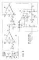
- this amplifier 20 has an impedance converter 83 as an input stage, which serves to adapt the relatively high output resistance of the resonance system 18 to the low input resistance of the subsequent first amplifier stage 84, the output signal of which via a further impedance converter 85 of the second amplifier stage 86 is fed.
- This two-stage structure of the Amplifier 20, in which each of the two stages has a comparatively low gain of approximately 1:10, has the advantage that it exhibits a significantly lower tendency to oscillate than a single-stage amplifier with a corresponding gain of 1: 100.
- the output signal of the second amplifier stage 86 is fed via a galvanically decoupling capacitor 87 to a control circuit 90 which keeps the DC voltage zero level constant at a predetermined value, which has a third impedance converter 91 with associated circuitry in its forward branch and a normal low-drift operational amplifier in its feedback branch 92 includes with appropriate wiring.
- the output DC voltage level thus stabilized against temperature-related fluctuations and due to component aging, to which an amplified, damped, sinusoidal oscillation signal is superimposed whenever the oscillation system 18 has been excited to oscillate by a light pulse received by the photodiode 17. is then fed directly to the circuit arrangement 22 for generating a time-significant signal, the main task of which is to determine the proper oscillation of the resonance system 18 and then to detect a predetermined zero crossing of this oscillation and to use it to generate a time-significant signal.
- integrated circuits are used as the impedance converters 83, 85 and 91, as are sold, for example, by National Semiconductor under the designation LH 0033-CG.
- each amplifier stage 84 or 86 is a programmable amplifier, such as that sold by the company Advanced Micro Devices under the name AM 733-T.
- an operational amplifier 92 is used, which is offered by the company Analog Devices under the name AD 741 LN.
- AD 741 LN Analog Devices
- the output signal of the impedance converter 83 is fed via a coupling capacitor 93 to the first input of the programmable amplifier 95 of the first amplifier stage 84 which is connected to ground via a resistor 94.
- the second input of amplifier 95 is terminated to ground via a resistor 96.
- a program resistor 97 which determines the gain of this amplifier stage, is connected between the programming inputs.
- the output signal of the first amplifier stage 84 is fed via a capacitor 98 and a voltage divider formed by the resistors 101 and 102 to the input of the second impedance converter 85, which is connected to the connection point of the two resistors 101 and 102. Between this point and the ground, a filter capacitor 103 is arranged for switching off RF interference.
- the output signal of the impedance converter 85 is fed via a galvanically isolating coupling capacitor 105 to the one input of the programmable amplifier 107 of the second amplifier stage 86 which is connected to ground via a resistor 106.
- the second input of this programmable amplifier 107 is connected to ground via a resistor 108, while the gain of this amplification stage is predetermined by a programming resistor 109.
- the AC output signal of the second amplifier stage 86 reaches the input of the third impedance converter 91 via the capacitor 87 for galvanic decoupling and a series resistor 110, the input DC voltage of which is roughly determined by a voltage divider, which is formed by the resistors 111 and 112 is formed, which are connected between a supply voltage source and the ground.
- the influencing of the DC input voltage of the impedance converter 91 which serves to keep its DC output voltage constant, takes place with the aid of the output signal of the feedback branch of the control circuit 90, which is fed to the common connection point of the resistors 110, 111 and 112 and the capacitor 87.
- a capacitor 113 which suppresses HF interference is also connected directly between the input of the impedance converter 91 and the ground.
- the output of the impedance converter 91 is connected to ground on the one hand via a resistor 114.
- the DC voltage signal appearing on it is fed via a resistor 115, a choke 116 suppressing AC components and a further resistor 117 to the inverting input of the operational amplifier 92, the non-inverting input of which is formed by means of a voltage divider formed by the resistors 118, 119 and 120 is set to a reference potential, which is kept free of RF interference by a filter capacitor 121.
- the output signal of the operational amplifier 92 is sent to the inverting input of the operational amplifier 92 on the one hand via a feedback branch consisting of a capacitor 125 and a resistor 126 connected in parallel thereto, and on the other hand via a resistor stood 127 on the above-mentioned connection point of the resistors 110, 111, 112 and the capacitor 87.
Description
Die Erfindung betrifft ein Verfahren und eine Vorrichtung zur Steuerung der Dynamik eines Entfernungsmessgerätes nach dem Prinzip der Lichtimpuls-Laufzeitmessung mit den im Oberbegriff von Anspruch 1 bzw. Anspruch 2 genannten Merkmalen.The invention relates to a method and a device for controlling the dynamics of a distance measuring device according to the principle of light pulse transit time measurement with the features mentioned in the preamble of claim 1 and claim 2, respectively.
Bei Entfernungsmessgeräten, die nach dem Prinzip der Laufzeitmessung von einzelnen Lichtimpulsen arbeiten, besteht grundsätzlich das Problem, eine zumindest kurzfristig exakt reproduzierbare zeitliche Korrelation zwischen dem Zeitpunkt, in dem ein Lichtimpuls am elektro-optischen Empfänger des Empfangskanals eintrifft und dem Zeitpunkt zu gewährleisten, in dem der Empfangskanal in Reaktion hierauf ein zeitsignifikantes Signal abgibt, durch das die entsprechende Lichtimpulse-Laufzeitmessung gestartet oder beendet wird.In the case of distance measuring devices which operate on the principle of the transit time measurement of individual light pulses, there is basically the problem of ensuring an exactly reproducible temporal correlation, at least in the short term, between the point in time at which a light pulse arrives at the electro-optical receiver of the receiving channel and the point in time at which in response to this, the receiving channel emits a time-significant signal by means of which the corresponding light pulse transit time measurement is started or ended.
Zur Erzielung dieser exakten zeitlichen Korrelation ist es aus der DE-A 2634627 bekannt, dem elektro-optischen Empfänger ein Resonanzsystem beispielsweise in Form eines Resonanz-Schwingkreises nachzuschalten, das durch das elektrische Signal, das der elektro-optische Empfänger beim Eintreffen eines Lichtimpulses erzeugt, zu einem eine Reihe von Perioden andauernden, in seiner Amplitude gedämpften Schwingungsvorgang angestossen wird. Es hat sich gezeigt, dass zumindest kurzfristig die Nulldurchgänge des hierbei vom Resonanzsystem erzeugten Schwingungssignals die erforderliche exakte zeitliche Korrelation zum Empfangszeitpunkt des Lichtimpulses aufweisen und sich daher sehr gut für die Erzeugung eines zeitsignifikanten Signals eignen. Zu diesem Zweck ist es erforderlich, das vom Resonanzsystem abgegebene Schwingungssignal mit Hilfe eines Verstärkers zu verstärken und anhand des Verstärkers-Ausgangssignals durch Komparatoren das ordnungsgemässe Anschwingen des Resonanzsystems festzustellen und einen geeigneten Nulldurchgang des Verstärker-Ausgangssignals zu detektieren und zur Auslösung eines zeitsignifikanten Signals zu verwenden.To achieve this exact temporal correlation, it is known from DE-A 2634627 to connect the electro-optical receiver with a resonance system, for example in the form of a resonant resonant circuit, which is generated by the electrical signal generated by the electro-optical receiver when a light pulse arrives. to a vibration of a period that is damped in its amplitude. It has been shown that, at least for a short time, the zero crossings of the vibration signal generated by the resonance system have the required exact time correlation at the time of reception of the light pulse and are therefore very suitable for generating a time-significant signal. For this purpose, it is necessary to amplify the oscillation signal emitted by the resonance system with the aid of an amplifier and to determine the proper oscillation of the resonance system on the basis of the amplifier output signal by means of comparators, and to detect a suitable zero crossing of the amplifier output signal and to use it to trigger a time-significant signal .
Wird nun bei einem sehr nahe am Messgerät befindlichen und/oder sehr stark reflektierenden Zielgegenstand das Resonanzsystem von einem sehr hellen Lichtimpuls zu einer so starken Schwingung angestossen, dass der ihm nachgeschaltete Verstärker übersteuert wird, so kann es zu erheblichen zeitlichen Verschiebungen der Nulldurchgänge des Verstärker-Ausgangssignal kommen. Damit ist aber die geforderte exakte zeitliche Korrelation zwischen diesen Nulldurchgängen und dem Empfangszeitpunkt des jeweiligen Lichtimpulses nicht mehr gegeben und eine genaue Laufzeitmessung unmöglich.If the resonance system is triggered by a very bright light pulse to a vibration so strong that the amplifier connected to it is overdriven, the resonance system in a target object located very close to and / or very strongly reflecting can be overdriven, so that there can be considerable time shifts in the zero crossings of the amplifier. Output signal coming. However, this means that the required exact time correlation between these zero crossings and the time of reception of the respective light pulse is no longer present and an exact transit time measurement is impossible.
Zur Vermeidung dieses Problems werden in der DE-A 2723835 ein Verfahren der eingangs genannten Art und eine Vorrichtung zur Durchführung dieses Verfahrens beschrieben. Gemäss diesem Stand der Technik ist dem Resonanzsystem des Empfangskanals ein Verstärker mit einem steuerbaren Verstärkungsfaktor nachgeschaltet, dessen Ausgangssignal durch einen Komparator mit einer vorgegebenen Referenzspannung verglichen wird. Übersteigt die Amplitude des Verstärker-Ausgangssignals die Referenzspannung, so erzeugt der Komperator ein Signal, das einerseits dazu führt, dass die gerade laufende Messung abgebrochen bzw. der so gewonnene Messwert nicht verwendet und dass andererseits der Verstärkungsfaktor des dem Resonanzsystem nachgeschalteten Verstärkersverringert wird. Mit diesem verringerten Verstärkungsfaktor wird dann der Messversuch dadurch wiederholt, dass ein neuer Lichtimpuls ausgesandt wird. Dieses Verfahren wird solange wiederholt, bis die Amplitude des Verstärker-Ausgangssignals die Referenzspannung nicht mehr übersteigt und somit eine genaue Laufzeitmessung gewährleistet ist.To avoid this problem, DE-A 2723835 describes a method of the type mentioned at the beginning and an apparatus for carrying out this method. According to this prior art, the resonance system of the receiving channel is followed by an amplifier with a controllable gain factor, the output signal of which is compared by a comparator with a predetermined reference voltage. If the amplitude of the amplifier output signal exceeds the reference voltage, the comparator generates a signal which, on the one hand, leads to the current measurement being aborted or the measurement value obtained not being used and, on the other hand, the gain factor of the amplifier connected downstream of the resonance system being reduced. The measurement attempt is then repeated with this reduced amplification factor in that a new light pulse is emitted. This process is repeated until the amplitude of the amplifier output signal no longer exceeds the reference voltage and thus an accurate transit time measurement is ensured.
Auch der US-A 3900261 ist ein Entfernungsmessgerät nach dem Prinzip der Lichtimpuls-Laufzeitmessung entnehmbar, bei dem die Verstärkung eines dem elektro-optischen Empfänger nachgeschalteten Verstärkers automatisch geregelt wird, um eine Übersteuerung zu vermeiden. Die Verwendung eines Resonanzsystems und ein Vergleich der Amplitude eines vom Verstärker abgegebenen Schwingungssignals mit einer Referenzspannung zur Erkennung der Übersteuerung wird dort jedoch nicht beschrieben.US-A 3900261 also shows a distance measuring device based on the principle of light pulse transit time measurement, in which the gain of an amplifier connected downstream of the electro-optical receiver is automatically regulated in order to avoid overdriving. However, the use of a resonance system and a comparison of the amplitude of an oscillation signal emitted by the amplifier with a reference voltage for detecting the overload is not described there.
Die bekannte Änderung des Verstärkungsfaktors eines Verstärkers im Empfangskanal eines Entfernungsmessgerätes zur Steuerung der Dynamik, d.h. zur Anpassung an verschieden weit entfernte und/oder verschieden stark reflektierende Zielgegenstände hat jedoch den Nachteil, dass mit ihr nur ein sehr kleiner Dynamikbereich überstrichen werden kann, der maximal in der Grössenordnung von 1:100 liegt. Überdies besteht die Gefahr einer mit grösser werdendem Verstärkungsfaktor zunehmenden Schwingneigung des Verstärkers, die die zeitliche Korrelation zwischen den Empfangszeitpunkten der einzelnen Lichtimpulse und dem jeweils zu detektierenden Nulldurchgang und somit die Messgenauigkeit erheblich verschlechtert.The known change in the amplification factor of an amplifier in the reception channel of a distance measuring device for controlling the dynamics, i.e. for adapting to target objects at different distances and / or reflecting at different intensities, however, has the disadvantage that it can only be used to sweep over a very small dynamic range, which is at most of the order of 1: 100. In addition, there is a risk of an increasing tendency of the amplifier to oscillate as the amplification factor increases, which considerably worsens the temporal correlation between the times of reception of the individual light pulses and the zero crossing to be detected, and thus the measuring accuracy.
Weiterhin hat ein kleiner Dynamikbereich zur Folge, dass der Entfernungsmessbereich eines solchen Messgerätes sehr eingeschränkt ist, weil die Helligkeit der Messlichtimpulse so klein gewählt werden muss, dass auch bei sehr nahe am Messgerät befindlichen und stark reflektierenden Zielgegenständen der Verstärker im Empfangskanal nicht übersteuert wird. Damit ist aber die maximale Reichweite eines solchen Entfernungsmessgerätes sehr gering.Furthermore, a small dynamic range means that the distance measuring range of such a measuring device is very limited, because the brightness of the measuring light pulses must be chosen so small that the amplifier in the receiving channel is not overdriven even when the target objects are very close and strongly reflecting. However, the maximum range of such a distance measuring device is very small.
Demgegenüber liegt der Erfindung die Aufgabe zugrunde ein Verfahren und eine Vorrichtung der eingangs genannten Art zu schaffen, die es ermöglichen, bei Abdeckung eines sehr grossen Dynamikbereiches zur Messung der Entfernung sowohl von beliebig nahen als auch von sehr weit entfernten Zielgegenständen für alle diese Messungen eine extrem hohe Messgenauigkeit zu erzielen.In contrast, the invention has for its object to provide a method and an apparatus of the type mentioned, which make it possible to cover an extremely large dynamic range for measuring the distance of both near and very distant target objects for all these measurements to achieve high measuring accuracy.
Zur Lösung dieser Aufgabe sieht die Erfindung die im Anspruch 1 niedergelegten Merkmale vor. Eine zur Durchführung eines erfindungsgemässen Verfahrens geeignete Vorrichtung ist im Anspruch 2 niedergelegt.To achieve this object, the invention provides the features set out in claim 1. A device suitable for carrying out a method according to the invention is set out in claim 2.
Durch die erfindungsgemässen Massnahmen kann der Verstärker auf einen Verstärkungsfaktor eingestellt werden, bei dem keinerlei Schwingneigung besteht. Solange der Verstärker also nicht übersteuert wird, stellt das Verstärker-Ausgangssignal eine exakte Reproduktion des dem Verstärker zugeführten Schwingungssignals dar, und seine Nulldurchgänge besitzen eine in der erforderlichen Weise reproduzierbare genaue zeitliche Korrelation zum Empfangszeitpunkt des jeweiligen Lichtimpulses; daher ist dieses Verstärker-Ausgangssignal auch bei sehr hohen Anforderungen an die Messgenauigkeit zur Erzeugung eines zeitsignifikanten Signals ohne weiteres geeignet.By means of the measures according to the invention, the amplifier can be set to a gain factor in which there is no tendency to oscillate. As long as the amplifier is not overdriven, the amplifier output signal represents an exact reproduction of the oscillation signal supplied to the amplifier, and its zero crossings have an exact time correlation at the time of reception of the respective light pulse, which is reproducible in the required manner; Therefore, this amplifier output signal is also suitable for generating a time-significant signal, even with very high demands on the measurement accuracy.
Um trotz des konstanten Verstärkungsfaktors auch bei sehr nahen und/oder sehr stark reflektierenden Zielgegenständen ein Übersteuern des Verstärkers zu verhindern, werden erfindungsgemäss Geräteparameter verändert, die die Amplitude des dem Verstärker zugeführten Schwingungssignals beeinflussen. Hierzu gehören insbesondere die Empfindlichkeit des elektro-optischen Empfängers, die durch Änderung seiner Vorspannung beeinflussbar ist, und die Helligkeit des am elektro-optischen Empfänger eintreffenden Lichtimpulse, die ihrerseits durch Steuerung der Senderleistung und/oder durch Veränderung des Dämpfungsfaktors eines im Messlichtweg angeordneten steuerbaren Dämpfungsgliedes verändert werden kann.In order to prevent overdriving of the amplifier despite the constant amplification factor even with very close and / or very strongly reflecting target objects, device parameters are changed according to the invention which influence the amplitude of the oscillation signal supplied to the amplifier. These include, in particular, the sensitivity of the electro-optical receiver, which can be influenced by changing its bias voltage, and the brightness of the light pulses arriving at the electro-optical receiver, which in turn by controlling the transmitter power and / or by changing the attenuation factor of a controllable attenuator arranged in the measurement light path can be changed.
Es stehen somit mehrere Geräteparameter zur Verfügung, die voneinander unabhängig verändert und somit entweder gleichsinnig oder gegensinnig zur Beeinflussung der Amplitude des dem Verstärker zugeführten Schwingungssignals eingesetzt werden können. Damit lässt sich ein ausserordentlich grosser Dynamikbereich von beispielsweise 1 : 3 x 10⁹ erreichen, so dass mit einem derart ausgestatteten Messgerät ein sehr grosser Entfernungsbereich mit hoher Genauigkeit ausgemessen werden kann.There are thus several device parameters available which can be changed independently of one another and can therefore be used either in the same direction or in opposite directions to influence the amplitude of the oscillation signal supplied to the amplifier. An extraordinarily large dynamic range of, for example, 1: 3 x 10⁹ can thus be achieved, so that a measuring device equipped in this way can measure a very large distance range with high accuracy.
Bei dem erfindungsgemässen Verfahren findet ein schrittweises Herantasten an den richtigen Dämpfungswert statt. Es wird zunächst ein erster Messversuch unternommen, bei dem alle die Amplitude des dem Verstärker zugeführten Schwingungssignals beeinflussenden Geräteparameter auf solche Werte geschaltet werden, dass diese Amplitude bei gegebener Entfernung und gegebenem Reflexionsvermögen des Zielgegenstandes möglichst gross wird.In the method according to the invention, a step-by-step approach to the correct damping value takes place. First, a first measurement attempt is made in which all device parameters influencing the amplitude of the vibration signal supplied to the amplifier are switched to values such that this amplitude becomes as large as possible for a given distance and given reflectivity of the target object.
Mit diesen Parameterwerten, d.h. also mit maximaler Senderleistung, minimaler Dämpfung im Messlichtweg und maximaler Vorspannung des elektro-optischen Empfängers wird ein erster Messversuch unternommen, bei dem ein Messlichtimpuls ausgesandt und empfangen wird. Zeigt der Vergleich des Verstärker-Ausgangssignals mit der Referenzspannung an, dass der Verstärker im linearen Bereich arbeitet, so wird das Messergebnis vom Messgerät erfasst und ausgewertet.With these parameter values, i.e. So with maximum transmitter power, minimum attenuation in the measurement light path and maximum bias of the electro-optical receiver, a first measurement attempt is made in which a measurement light pulse is transmitted and received. If the comparison of the amplifier output signal with the reference voltage indicates that the amplifier is operating in the linear range, the measurement result is recorded and evaluated by the measuring device.
Ist der Verstärker jedoch übersteuert, so wird der erste Messversuch verworfen und zur Durchführung eines zweiten Messversuches wenigstens einer der zur Verfügung stehenden Geräteparameter auf einen anderen Wert umgeschaltet, der zu einer Dämpfung, d.h. zu einer Verringerung der Amplitude des dem Verstärker zugeführten Schwingungssignals führt. Da beim ersten, wegen der Übersteuerung des Verstärkers fehlgeschlagenen Messversuch nur die Tatsache nicht aber das Ausmass der Übersteuerung festgestellt wird, ist nicht bekannt, welcher Dämpfungsfaktor gewählt werden muss, um in den Linearitätsbereich des Verstärkers zu kommen.However, if the amplifier is overdriven, the first measurement attempt is rejected and at least one of the available device parameters is switched over to another value to carry out a second measurement attempt, which leads to damping, i.e. leads to a reduction in the amplitude of the oscillation signal supplied to the amplifier. Since the first measurement attempt, which failed due to the amplifier being overdriven, only the fact and not the extent of the overdrive is ascertained, it is not known which damping factor must be selected in order to reach the linearity range of the amplifier.
Daher wird zunächst ein Grunddämpfungswert eingeschaltet, der erfindungsgemäss so gewählt ist, dass er etwas kleiner als der Dynamikbereich des Verstärkers, d.h. kleiner als das Verhältnis der kleinsten, durch den Verstärker gerade noch einwandfrei verarbeitbaren Signalamplitude zur oberen Grenze des Linearitätsbereiches des Verstärkers ist. Dadurch wird verhindert, dass ein Signal, durch das der Verstärker beim ersten Messversuch nur ganz gering übersteuert wurde, beim zweiten Messversuch so stark bedämpft wird, dass es wegen seiner nunmehr zu kleinen Amplitude nicht mehr ausgewertet werden kann.Therefore, a basic attenuation value is first switched on, which according to the invention is selected so that it is somewhat smaller than the dynamic range of the amplifier, i.e. is smaller than the ratio of the smallest signal amplitude that can just be processed perfectly by the amplifier to the upper limit of the linearity range of the amplifier. This prevents a signal, by which the amplifier was only slightly overdriven during the first measurement attempt, from being attenuated so strongly during the second measurement attempt that it can no longer be evaluated because of its now too small amplitude.
Führt auch der zweite Messversuch zu einer Übersteuerung des Verstärkers, so sind weitere Messversuche mit erhöhten Dämpfungswerten erforderlich. Erfindungsgemäss sind die durch Umschalten der Geräteparameter auf andere Werte zur Verfügung stehenden erhöhten Dämpfungswerte so gestaffelt, dass sie möglichst nahe unterhalb fortlaufender ganzzahliger Potenzen des Grunddämpfungswertes liegen und diese mit Sicherheit nicht übersteigen. Setzt man also den Grunddämpfungswert gleich G, so kann dann, wenn auch beim zweiten Messversuch eine Übersteuerung des Verstärkers auftritt, ein dritter Versuch mit einem Dämpfungswert G2 und, bei erneuter Übersteuerung, ein vierter Messversuch mit einem Dämpfungswert G3 usw. unternommen werden, ohne dass die Gefahr besteht, dass das dem Verstärker zugeführte Schwingungssignal zu stark bedämpft wird.If the second measurement attempt also leads to the amplifier being overdriven, further measurement attempts with increased damping values are necessary. According to the invention, the increased damping values available by switching the device parameters to other values are staggered in such a way that they are as close as possible below continuous integer powers of the basic damping value and certainly do not exceed them. If the basic damping value is set to G, a third attempt can be made with an attenuation value G 2 and, if overdriving occurs, a fourth measurement attempt with an attenuation value G 3 etc. if overdriving occurs. without the risk that the vibration signal supplied to the amplifier is damped too much.
Auf diese Weise wird erreicht, dass mit einer sehr geringen Zahl von Messversuchen der richtige Dämpfungswert automatisch eingestellt werden kann, ohne dass das Ausmass der Übersteuerung bei den einzelnen Messversuchen bekannt ist oder gemessen werden muss.In this way it is achieved that the correct damping value can be set automatically with a very small number of measurement attempts, without the extent of the overload in the individual measurement attempts being known or having to be measured.
Die Erfindung wird im folgenden anhand eines Ausführungsbeispiels unter Bezugnahme auf die Zeichnung erläutert; in dieser zeigt:The invention is explained below using an exemplary embodiment with reference to the drawing; in this shows:
- Fig. 1 eine schematische Darstellung der wesentlichen Teile eines nach dem erfindungsgemässen Verfahren aufgebauten und arbeitenden Entfernungsmessgerätes, und1 shows a schematic illustration of the essential parts of a distance measuring device constructed and operating according to the method according to the invention, and
- Fig. 2 ein Schaltbild eines bevorzugten, dem Resonanzsystem des Empfangskanals nachgeschalteten Verstärkers aus Fig. 1.Fig. 2 is a circuit diagram of a preferred, the Resonance system of the amplifier downstream of the receiving channel from FIG. 1.
Wie in Fig. 1 dargestellt, besitzt ein nach dem erfindungsgemässen Verfahren arbeitendes Entfernungsmessgerät einen Sender 1, der beispielsweise eine Laser-Sendediode 3 und eine Schaltungsanordnung 4 umfasst, die zum Ansteuern der Sendediode 3 dient. Die Schaltungsanordnung 4 besteht im wesentlichen aus einem «langsam» aufladbaren Energiespeicher, beispielsweise in Form einer Kapazität, und einem steuerbaren elektronischen Schalter, der dazu dient, die im Energiespeicher angesammelte Energie schnell über die Sendediode 3 zu entladen, worauf die Sendediode 3 mit der Emission eines Laser-Lichtimpulses reagiert.As shown in FIG. 1, a distance measuring device operating according to the method according to the invention has a transmitter 1, which comprises, for example, a laser transmission diode 3 and a circuit arrangement 4 which serves to control the transmission diode 3. The circuit arrangement 4 essentially consists of a “slowly” rechargeable energy store, for example in the form of a capacitance, and a controllable electronic switch which serves to quickly discharge the energy accumulated in the energy store via the transmitter diode 3, whereupon the transmitter diode 3 emits of a laser light pulse reacts.
Die Ansteuerung dieses elektronischen Schalters kann für einen periodischen Betrieb mit Hilfe eines Oszillators 6 erfolgen, der mit vorgegebener Frequenz schwingt. Alternativ oder zusätzlich hierzu kann aber auch vorgesehen werden, dass der steuerbare elektronische Schalter zur Auslösung von Einzelimpulsen über eine Steuerleistung 8 von einer zentralen Ablaufsteuerung 10 getriggert wird.This electronic switch can be controlled for periodic operation with the aid of an
Ein erster Teil eines jeden von der Sendediode 3 erzeugten Lichtimpulses wird als Messlichtimpuls verwendet, d.h. er wird über eine Lichtleitfaser 11 und eine Sendeoptik 12, die in Fig. 1 schematisch vereinfacht als einzelne Linse dargestellt ist, zum Zielgegenstand hin ausgesandt, dessen Entfernung gemessen werden soll.A first part of each light pulse generated by the transmitter diode 3 is used as a measurement light pulse, i.e. it is sent via an optical fiber 11 and a
Der zweite Teil eines jeden von der Sendediode 3 erzeugten Lichtimpulses wird als Referenzlichtimpuls verwendet, d.h. er wird durch eine Y-förmige Verzweigung 24 aus der Sende-Lichtleitfaser 11 ausgekoppelt und in einen Referenzlichtweg eingespeist, der zunächst eine Lichtleitfaser- 'Spule 25 und hinter dieser eine weitere Y-förmige Verzweigung 26 umfasst, hinter der der Referenzlichtweg in zwei funktional zueinander parallele Abschnitte 27 und 34 mit unterschiedlichen Längen aufgeteilt ist. Diese beiden Abschnitte vereinigen sich an einem optischen Umschalter 38 zu einem einzigen Lichtweg 28, der zu einer Photodiode 17 führt, die den elektro-optischen Empfänger des Empfangskanals 16 bildet.The second part of each light pulse generated by the transmitter diode 3 is used as a reference light pulse, i.e. it is decoupled from the transmission optical fiber 11 by a Y-
An der weiteren Y-förmigen Verzweigung 26 wird jeder Referenzlichtimpuls wieder in zwei Teile aufgespalten, von denen sich der eine längs des kurzen Abschnittes 27 und der andere längs des langen Abschnittes 34 weiterbewegt. In Abhängigkeit von der Stellung des optischen Umschalters 38, der über eine Leitung 31 von der zentralen Ablaufsteuerung 10 betätigt wird, kann nur der eine oder der andere dieser beiden Teile eines jeden Referenzlichtimpulses über den Lichtweg 28 zur Photodiode 17 gelangen, während der jeweils andere Teil unterdrückt wird.At the further Y-
Bei einem Zielgegenstand, der einen hinreichend grossen Abstand aufweist, befindet sich der optische Umschalter 38 in einer Stellung, in der er den kurzen Abschnitt 27 des Referenzlichtweges mit dem Lichtweg 28 verbindet, so dass ein Referenzlichtimpuls, der an der Verzweigung 24 von einem von der Sendediode 3 erzeugten Lichtimpuls abgezweigt wurde, als erster an der Photodiode 17 anlangt. Derjenige Teil des zugehörigen Messlichtimpulses, der vom Zielgegenstand zum Messgerät reflektiert und mit Hilfe einer wieder vereinfacht als einzelne Linse dargestellten Empfangsoptik 14 in einen Lichtweg 15 eingespeist wird, der ebenfalls zur Photodiode 17 führt, kommt in diesem Fall nach dem Referenzlichtimpuls an der Photodiode 17 an.In the case of a target object which is at a sufficiently large distance, the optical switch 38 is in a position in which it connects the
Jedes der beiden elektrischen Signale, die von der Photodiode 17 in Antwort auf Empfang dieser beiden Lichtimpulse erzeugt werden, dient zum Anstossen eines Schwingungsvorganges in einem der Photodiode 17 nachgeschalteten Resonanzsystem 18, das beispielsweise gemäss der DE-A 2634627 als Parallel-Resonanzschwingkreis ausgebildet sein kann. Alternativ hierzu kann dieses Resonanzsystem 18 aber auch von einem Serien-Resonanzschwingkreis oder einem anderen elektromagnetischen Schwingungssystem gebildet sein.Each of the two electrical signals, which are generated by the
Entscheidend ist, dass das Resonanzsystem 18 durch das von der Photodiode 17 beim Empfang eines jeden Lichtimpulses abgegebene Signal zu einem gedämpften Schwingungsvorgang angeregt wird, der im allgemeinen sinusförmig ist und mit exponentiell abnehmender Amplitude der einzelnen Halbschwingungen verläuft. Wenn der Abstand des Zielgegenstandes gross ist, dann ist auch der Zeitabstand zwischen den beiden Lichtimpulsen gross und der erste Schwingungsvorgang, der durch den Empfang des Referenzlichtimpulses ausgelöst wird, ist vollständig abgeklungen, wenn der Messlichtimpuls an der Photodiode 17 eintrifft und den zweiten Schwingungsvorgang auslöst.It is crucial that the
Das bei jedem dieser Schwingungsvorgänge vom Resonanzsystem 18 abgegebene Signal wird durch einen nachgeschalteten Verstärker 20 (siehe Fig. 2) verstärkt und dann einer zur Erzeugung eines zeitsignifikanten Signals dienenden Schaltungsanordnung 22 zugeführt. Hauptaufgabe dieser Schaltungsanordnung 22 ist es, immer dann, wenn von der Photodiode 17 ein Lichtimpuls empfangen worden ist, ein zeitsignifikantes Signal, d.h. ein Signal zu erzeugen, dessen zeitliche Lage in genau definierter Weise mit dem zeitlichen Schwerpunkt des betreffenden Lichtimpulses korreliert ist.The signal emitted by the
Dieses zeitsignifikante Signal kann beispielsweise eine fallende oder steigende Impulsflanke sein. Aus dem oben Gesagten ergibt sich, dass für jedes Paar von Mess- und Referenzlichtimpulsen, die nacheinander an der Photodiode 17 eintreffen, zwei zeitsignifikante Signale erzeugt werden, die ebenfalls nacheinander auftreten. Das jeweils zuerst auftretende zeitsignifikante Signal wird immer dazu verwendet, die Laufzeitmessung des betreffenden Messlichtimpulses zu starten, während das zweite dazu verwendet wird, diese Laufzeitmessung zu beenden. In dem hier betrachteten Fall, in welchem der Messlichtimpuls von einem Zielgegenstand mit grosser Entfernung reflektiert wird, wird zuerst das dem Referenzlichtimpuls entsprechende zeitsignifikante Signal erzeugt, das somit als Startsignal für die Laufzeitmessung dient. Das dem Messlichtimpuls entsprechende zeitsignifikante Signal wird etwas später erzeugt und dient daher zur Beendigung der Laufzeitmessung.This time-significant signal can be, for example, a falling or rising pulse edge. It follows from the above that for each pair of measurement and reference light pulses that arrive successively at the
Zu diesem Zweck werden die beiden zeitsignifikanten Signale über eine Leitung 23 einer Zeitmessvorrichtung zugeführt, die, da sie nicht Gegenstand der vorliegenden Erfindung ist, der Einfachheit halber mit in die zentrale Ablaufsteuerung 10 aufgenommen wurde.For this purpose, the two time-significant signals are fed via a
Zweck der hinter der Y-förmigen Verzweigungsstelle 24 angeordneten Lichtleitfaser-Spule 25 ist es, auch den dem Empfangskanal 16 über den kurzen Abschnitt 27 des Referenzlichtweges zugeführten Referenzlichtimpulses in unvermeidlicher Weise miterzeugten Störungen bereits weitgehend abgeklungen sind.The purpose of the
Ist das der Photodiode 17 nachgeschaltete Resonanzsystem 18 durch einen empfangenen Lichtimpuls zu einem gedämpften Schwingungsvorgang angestossen worden, so kann ein erneuter Anstoss, der erfolgt, solange der erste Schwingungsvorgang noch nicht weitgehend wieder abgeklungen ist, zu undefinierten Schwingungsverhältnissen führen, die eine Erzeugung eines dem zweiten Anstoss zeitlich eindeutig zugeordneten zeitsignifikanten Signals durch die Schaltungsanordnung 22 unmöglich machen.If the
Daher ist vorgesehen, dass die Schaltungsanordnung 22 sofort nachdem sie das ordnungsgemässe Anschwingen des Resonanzsystems 18 erkannt hat, wodurch die Erzeugung eines zeitsignifikanten Signals ausgelöst wird, für einen Mindestzeitraum gesperrt wird, der etwas grösser als die Freiwerdezeit des Empfangskanals 16 ist, d.h. etwas grösser als derjenige Zeitraum, der verstreichen muss, bis das Resonanzsystem 18 nach einem vorausgehenden Anstoss ordnungsgemäss ein zweites Mal angestossen werden kann. Frühestens nach dem Verstreichen dieses Mindestzeitabstandes erhält die Schaltungsanordnung 22 von der Ablaufsteuerung 10 über die Leitung 29 ein Rücksetz- bzw. Vorbereitungssignal, das sie für Schwingungsvorgänge des Resonanzsystems 18 wieder empfänglich macht.It is therefore provided that the
Nun kann es bei sehr kleinen Abständen zwischen der Messvorrichtung und dem Zielgegenstand geschehen, dass der vom Zielgegenstand reflektierte Messlichtimpuls vor dem über die Lichtleitfaser 25, 27 und 28 laufenden Referenzlichtimpuls, gleichzeitig mit dem Referenzlichtimpuls oder innerhalb des oben erwähnten Mindestzeitabstandes nach dem Referenzlichtimpuls an der Empfangsdiode 17 eintrifft. In all diesen Fällen schwingt zwar das Resonanzsystem 18 zunächst einmal an und es wird in Antwort hierauf von der Schaltungsanordnung 22 auch ein erstes und somit die Laufzeitmessung startendes zeitsignifikantes Signal erzeugt. Da in diesen Fällen aber der jeweils später der beiden Lichtimpulse zu einem Zeitpunkt an der Empfangs-Photodiode 17 eintrifft, in welchem die Schaltungsanordnung 22 noch nicht wieder freigegeben ist, wird kein zweites, die begonnene Laufzeitmessung anhaltendes zeitsignifikantes Signal mehr erzeugt. Da für jedes derartige Messgerät eine maximale Messreichweite vorgebbar ist, erreicht die weiterlaufende Laufzeitmessung sehr schnell einen über die Lichtgeschwindigkeit mit dieser maximalen Messreichweite verknüpften Wert, dessen Überschreiten von der Ablaufsteuerung 10 erkannt und zum Anlass für das Abbrechen der betreffenden Laufzeitmessung und für die Auslösung weiterer Steuerbefehle genommen wird.Now, with very small distances between the measuring device and the target object, it can happen that the measuring light pulse reflected by the target object before the reference light pulse passing through the
Einer dieser Steuerbefehle, der über eine Leitung 31 an den optischen Umschalter 38 wiedergegeben wird, veranlasst diesen, statt des kurzen Abschnittes 27 den langen Abschnitt 34 des Referenzlichtweges mit dem zur Photodiode 17 führenden Lichtweg 28 zu verbinden, wodurch der gleichzeitig mit dem Aussenden eines Messlichtimpulses von der Sendediode 3 abgegebene Referenzlichtimpuls um wenigstens das Zweifache der oben genannten Freiwerdezeit T stärker verzögert wird, als beim Durchlaufen des kürzeren Abschnitts 27.One of these control commands, which is reproduced via a
Damit der Referenzlichtimpuls an der Empfangsdiode 17 unabhängig davon, ob er über den kurzen oder den langen Abschnitt des Referenzlichtweges geführt wurde, immer die gleiche Intensität besitzt, ist in den kurzen Abschnitt 27 ein Dämpfungsglied 39 mit einem festen, der durch den langen Abschnitt 34 verursachten Dämpfung entsprechenden Dämpfungswert eingefügt.So that the reference light pulse on the receiving
Hat nun also, wie dies oben beschrieben wurde, die Ablaufsteuerung 10 bei einer Stellung des Umschalters 38 bei der der über den kurzen Abschnitt 27 des Referenzlichtweges laufende Referenzlichtimpuls zum Empfangskanal 16 gelangt, festgestellt, dass zwar eine Laufzeitmessung gestartet, nicht aber innerhalb eines vernünftigen Zeitraums gestoppt worden ist, so interpretiert sie dies als eine sehr geringe Entfernung zwischen Messvorrichtung und Zielgegenstand und veranlasst in Antwort hierauf den Umschalter 38 in die andere Stellung überzuwechseln, in der der über den langen Abschnitt 34 laufende Referenzlichtimpuls der Photodiode 17 zugeführt wird. Wird hierauf ein neuer Lichtimpuls beispielsweise dadurch ausgelöst, dass der Schaltungsanordnung 4 über die Leitung 8 ein von der Ablaufsteuerung 10 ausgehendes Triggersignal zugeführt wird, so erreicht der an einem nur einen geringen Abstand von der Messvorrichtung aufweisenden Zielgegenstand reflektierte Messlichtimpuls die Empfangsdiode 17 mit Sicherheit so frühzeitig vor dem durch den langen Abschnitt 34 verzögerten Referenzlichtimpuls, dass beide Lichtimpulse durch den Empfangskanal 16 einwandfrei erfasst und zur Erzeugung von zeitsignifikanten Signalen ausgewertet werden können. Es tritt hier zwar eine Umkehr der Reihenfolge ein, d.h. die Laufzeitmessung wird durch den Messlichtimpuls gestartet und durch den Referenzlichtimpuls beendet. Dies hat lediglich zur Folge, dass der gemessene Zeitabstand Δt nicht direkt die gesuchte Laufzeit AT des Messlichtimpulses wiedergibt, sondern mit dieser über die Gleichung ΔT = 2τ + δ-Δt verknüpft ist, wobei 2τ + 8 die durch den langen Referenzlichtweg 25, 34, 27 bedingte, sehr genau ausmessbare Verzögerung bedeutet.So, as has been described above, when the switch 38 is in a position in which the reference light pulse running over the
Hierdurch wird es möglich, Entfernungen von 0 cm bis zur maximalen Reichweite des Messgerätes mit einer gleichbleibenden absoluten Genauigkeit von weniger als ±1 cm auszumessen.This makes it possible to measure distances from 0 cm to the maximum range of the measuring device with a constant absolute accuracy of less than ± 1 cm.
Wie Fig. 1 weiterhin zeigt, wird das vom Verstärker 20 abgegebene Signal nicht nur der Schaltungsanordnung 22 zur Erzeugung eines zeitsignifikanten Signals sondern auch einem Komparator 41 zugeführt, der dieses Verstärkersignal mit einer vorgegebenen Referenzspannung vergleicht. Diese Referenzspannung ist so gewählt, dass sie in etwa der oberen Grenze des Linearitätsbereiches des Verstärkers 20 entspricht. Wird nämlich dieser Linearitätsbereich überschritten, so kann es zu erheblichen zeitlichen Verschiebungen der Nulldurchgänge des vom Verstärker 20 abgegebenen Schwingungssignals bezüglich des Anstosszeitpunktes des Resonanzsystems 18 kommen, so dass eine einwandfreie zeitliche Zuordnung dieser Nulldurchgänge bzw. eines von einem solchen Nulldurchgang abgeleiteten zeitsignifikanten Signals zum Empfangszeitpunkt des auslösenden Lichtimpulses nicht mehr gegeben ist.As FIG. 1 further shows, the signal emitted by the
Bei einem Messgerät, das einerseits zur Erzielung einer möglichst grossen Maximalreichweite mit einer möglichst hohen Sendeleistung und einer hohen Empfindlichkeit auf der Empfängerseite arbeitet, andererseits aber auch in der Lage sein soll, die Entfernung gering beabstandeter, unter Umständen eine hohe Reflektivität besitzender Zielgegenstände exakt auzumessen, kann es insbesondere in den zuletztgenannten Fällen zu einer Übersteuerung des Verstärkers 20 kommen, da die Amplitude des vom Resonanzsystems 18 abgegebenen Schwingungssignals von der Stärke des Anstosses, d.h. also von der Helligkeit des von der Photodiode 17 empfangenen Lichtimpulses abhängt. Tritt eine solche Übersteuerung des Verstärkers 20 ein, so wird dies vom Komparator 41 erkannt, der über die Leitung 42 ein entsprechendes Übersteuerungssignal an die Ablaufsteuerung 10 abgibt. Aufgrund dieses Übersteuerungssignals wird von der Ablaufsteuerung 10 der eben gewonnene Messwert verworfen und die Wiederholung der Messung mit geänderten Geräteparametern eingeleitet, wie dies im folgenden beschrieben wird.In the case of a measuring device which, on the one hand, works to achieve the greatest possible maximum range with the highest possible transmission power and high sensitivity on the receiver side, but on the other hand is also supposed to be able to measure the distance of closely spaced, possibly reflective target objects, In particular, in the latter cases, the
Bei der aus dem Verstärker 20 und der Schaltungsanordnung 22 bestehenden Untereinheit des Empfangskanals 16 lässt sich bei einer angestrebten Messgenauigkeit von weniger als ±1 cm eine Dynamik von ca. 15 erreichen, d.h. zwischen dem kleinsten von der Schaltungsanordnung 22 gerade noch präzise erkenn- und verarbeitbaren Signal und dem grössten, gerade noch innerhalb des Komparator 41 überwachten Linearitätsbereichs des Verstärkers 20 abgegebenen Signal besteht ein Verhältnis von ungefähr 1:15.With the subunit of the receiving
Hat nun die Ablaufsteuerung 10 aufgrund eines vom Komparator 41 erzeugten Übersteuerungssignals erkannt, dass der Verstärker 20 über seinen Linearitätsbereich hinaus getrieben wurde, so muss sie bei der Wiederholung des Messversuches dafür sorgen, dass das Resonanzsystem 18 weniger stark angestossen wird. Dies kann durch eine Verringerung der Sendeleistung und/ oder durch eine Verringerung der Empfindlichkeit der Messanordnung auf der Empfängerseite erreicht werden. Diese beiden Möglichkeiten sollen im folgenden unter dem Begriff der «Dämpfung des Empfangssignals» zusammengefasst werden.If the sequence controller 10 has now recognized on the basis of an overdrive signal generated by the comparator 41 that the
Es ist nun von besonderer Bedeutung, dass nach einer vom Komparator41 gemeldeten Übersteuerung des Verstärkers 20 bei der Wiederholung des Messversuches nur eine Dämpfung vorgenommen wird, die kleiner als der oben erwähnte Dynamikbereich 1 : 15 ist. Würde man nämlich gleich beim ersten Dämpfungsschritt beispielsweise um einen Faktor 20 dämpfen, so könnte es geschehen, dass dann, wenn beim ersten, gescheiterten Messversuch nur eine geringe Übersteuerung des Verstärkers 20 vorhanden war, beim nachfolgenden Messversuch kein von der Schaltungsanordnung 22 verarbeitbares Signal mehr erhalten wird.It is now of particular importance that after an overdrive of the
Durch den Dynamikbereich der aus Verstärker 20 und Schaltungsanordnung 22 bestehenden Untereinheit ist also eine Grunddämpfung vorgegeben, die bei einem einzelnen Dämpfungsschritt nicht überschritten werden darf.The dynamic range of the subunit consisting of
Zeigt sich bei der Wiederholung des Messversuches mit um die Grunddämpfung abgeschwächten Empfangssignal, dass der Verstärker 20 noch immer übersteuert wird, so muss natürlich eine weitere Dämpfungsstufe eingeschaltet und dieses Verfahren solange wiederholt werden, bis der Verstärker 20 wieder in seinem Linearitätsbereich arbeitet. Um die eben beschriebene mehrstufige Dämpfung zu erzielen, stehen bei einer erfindungsgemässen Messanordnung mehrere Parameter zur Verfügung.If, when the measurement attempt is repeated with the received signal weakened by the basic attenuation, it becomes apparent that the
Der erste dieser Parameter ist die Leistung der Sendediode 3, die durch eine unterschiedliche hohe Aufladung des in der Schaltungsanordnung 4 zur Lichtimpulserzeugung enthaltenen Energiespeichers verändert werden kann. Das hierzu erforderliche Signal kommt, wie bereits erwähnt, von der Ablaufsteuerung 10 und wird der Schaltungsanordnung 4 bei dem Ausführungsbeispiel nach Fig. 1 über die Leitung 43 zugeführt. Durch die Veränderung der Sendeleistung lässt sich ein Dämpfungsverhältnis etwa in der Grössenordnung 1:4 erzielen.The first of these parameters is the power of the transmitter diode 3, which can be changed by charging the energy store contained in the circuit arrangement 4 for generating light pulses with different levels of charge. The signal required for this comes, as already mentioned, from the sequence controller 10 and is supplied to the circuit arrangement 4 in the exemplary embodiment according to FIG. 1 via the
Als weiterer Parameter steht die Empfindlichkeit der Empfangs-Photodiode 17 zur Verfügung, die durch Änderung der Vorspannung dieser Diode je nach Diodentyp im Verhältnis 1:6 bis 1:7 verändert werden kann. Dies geschieht bei dem Ausführungsbeispiel nach Fig. 1 mit Hilfe der Vorspannungssteuerung 44, die über die Leitung 45 die entsprechenden Befehlssignale von der zentralen Ablaufsteuerung 10 erhält.As a further parameter, the sensitivity of the receiving
Als dritter Parameter zur Verringerung der Empfangs-Empfindlichkeit ist schliesslich ein optisches Dämpfungsglied 46 mit veränderbarem Dämpfungsfaktor in den Lichtweg 15 zwischen der Empfangsoptik 14 und der Empfangs-Photodiode 17 eingeschaltet, wobei der Dämpfungsfaktor dieses veränderbaren optischen Dämpfungsgliedes 46 von der Ablaufsteuerung 10 über die Leitung 47 gesteuert wird.As a third parameter to reduce the Finally, reception sensitivity is switched on an
Als optisches Dämpfungsglied 46 kann beispielsweise eine Irisblende verwendet werden, die stufenweise verengt bzw. erweitert werden kann. Vorzugsweise wird hier ein Dämpfungsglied verwendet, mit dem sich beispielsweise ein Dämpfungsfaktor von 1:160 erzielen lässt.An iris diaphragm, for example, can be used as the
Dieser Dämpfungsfaktor ist zwar wesentlich grösser als der Dynamikbereich des Verstärkers 20 und der nachgeschalteten Schaltungsanordnung 22.This damping factor is admittedly substantially larger than the dynamic range of the
Geht man aber davon aus, dass der Komparator 41 bei einem ersten, unter voller Sendeleistung und bei voller Empfindlichkeit der Messanordnung durchgeführten Messversuch eine Übersteuerung angezeigt hat, so bedeutet dies lediglich, dass bei der ersten Wiederholung nicht sofort das Dämpfungsglied 46 eingeschaltet werden darf. Vielmehr ist es zweckmässig zuerst einen der beiden anderen Dämpfungsparameter einzusetzen. Kommt es dann bei der mit diesem Parameter durchgeführten Wiederholung des Messversuches zu einer erneuten Übersteuerung des Verstärkers 20, so wird der andere der beiden nur eine relativ geringe Dämpfung bewirkende Parameter zusätzlich eingeschaltet. Mit den oben beispielsweise angeführten Zahlenwerten bedeutet dies, dass bei der zweiten Wiederholung nunmehr mit einer Dämpfung von ungefähr 1:24 bis 1:28 gearbeitet wird. Führt auch das wieder zu einer Übersteuerung des Verstärkers 20, so können die beiden bisher verwendeten Dämpfungsmöglichkeiten wieder abgeschaltet und statt dessen das optische Dämpfungsglied 46 eingeschaltet werden, da dessen Dämpfungsfaktor von 1:160 mit Sicherheit kleiner als das Produkt aus dem bisher verwendeten Dämpfungsfaktor 1:24 und der Dynamik 1:15 des Verstärkers 20 und der nachgeschalteten Schaltungsanordnung 22 ist.If, however, it is assumed that the comparator 41 has indicated an overload during a first measurement attempt carried out with full transmission power and with full sensitivity of the measuring arrangement, this only means that the
Wird auch bei der allein mit dem Dämpfungsglied 46 durchgeführten Wiederholung des Messversuches der Verstärker 20 übersteuert, so können erforderlichenfalls wieder die beiden anderen Dämpfungsparameter eingesetzt werden. Insgesamt lässt sich auf diese Weise ein Dynamikbereich überstreichen, der grösser als 1:55000 ist. Durch die zusätzliche Verwendung eines Filters mit einem Dämpfungsverhältnis beispielsweise ebenfalls von 1:55 000 lässt sich also ohne weiteres ein Dynamikbereich von 1:3.109 erreichen, wodurch es möglich wird, einerseits eine sehr hohe Senderleistung und eine sehr hohe Empfindlichkeit für eine möglichst grosse Reichweite vorzusehen und andererseits auch noch bei sehr gut reflektierenden Zielgegenständen beliebig kurze Abstände mit einer hohen Genauigkeit auszumessen.If the
Es hat sich gezeigt, dass eine optimale Messgenauigkeit dann erzielbar ist, wenn die Amplituden bzw. Intensitäten der von der Photodiode 17 empfangenen, jeweils zum Start bzw. Stop ein und derselben Laufzeitmessung dienenden, d.h. also zusammengehörenden Mess- und Referenzlichtimpulse einander möglichst gleich sind. Da, wie eben ausgeführt, die Intensitätdes Messlichtimpulses gemäss einem Merkmal der Erfindung innerhalb weiter Grenzen veränderbar ist, ist zur jeweiligen Anpassung des zugehörigen Referenzlichtimpulses in denjenigen Teil 28 des Referenzlichtweges, der sowohl den unmittelbar als auch den verzögert zugeführten Referenzlichtimpuls weiterleitet, ein einstellbares Dämpfungsglied 48 eingefügt, das über die Leitung 49 von der Ablaufsteuerung 10 gesteuert wird.It has been shown that an optimal measurement accuracy can be achieved if the amplitudes or intensities of the one received by the
Bei einer nach dem erfindungsgemässen Verfahren arbeitenden Messvorrichtung ist dem gemäss Fig. 2 über einen Vorwiderstand 78 und einen Glättungskondensator 79 mit Spannung versorgten Photoempfänger dieser Messvorrichtung, also z.B. der Photodiode 17 ein Resonanzsystem 18 nachgeschaltet, das vorteilhafterweise aus einem den Arbeitswiderstand der Photodiode 17 bildenden Parallel-Resonanzschwingkreis besteht, der aus einer Spule 80, der Sperrschichtkapazität der Photodiode 17 und einer zusätzlichen, parallelgeschalteten, externen Kapazität 81 sowie einem Widerstand 82 aufgebaut ist.In the case of a measuring device operating according to the method according to the invention, the photo-receiver of this measuring device, which is supplied with voltage via a
Dieses Resonanzsystem wird durch einen von der Photodiode 17 empfangenen Lichtimpuls zu einem sinusförmigen Schwingungsvorgang angeregt, dessen zweite Halbwelle im allgemeinen die grösste Amplitude besitzt und der dann nach einem exponentiellen Dämpfungsgesetz wieder abklingt.This resonance system is excited by a light pulse received by the
Es hat sich gezeigt, dass zumindest kurzfristig, mit Sicherheit also für den äusserst kurzen Zeitraum, innerhalb dessen auch bei grossen auszumessenden Entfernungen Referenzlichtimpulse und Messlichtimpuls bei der Empfangs-Photodiode 17 eintreffen, die Nulldurchgänge dieses Schwingungsvorganges in ausserordentlich exakter, reproduzierbarer Weise mit dem zeitlichen Schwerpunkt des anstossenden Lichtimpulses korreliert sind. Dies gilt auch für die Nulldurchgänge des Ausgangssignals des dem Resonanzsystem 18 nachgeschalteten Verstärkers 20, solange dieser Verstärker nicht übersteuert, d.h. in seinem Lineraritätsbereich betrieben wird.It has been shown that, at least for a short time, certainly for the extremely short period within which reference light pulses and measurement light pulses arrive at the receiving
Somit sind die Nulldurchgänge des Ausgangssignals des Verstärkers 20 ausserordentlich gut geeignet, um ein zeitsignifikantes Signal auszulösen, mit dessen Hilfe die zur Laufzeitmessung des Lichtimpulses erforderliche Zeitmessung entweder gestartet oder beendet wird.Thus, the zero crossings of the output signal of the
Wie Fig. 2 weiterhin zeigt, besitzt dieser Verstärker 20 als Eingangsstufe einen Impedanzwandler 83, der dazu dient, den relativ hohen Ausgangswiderstand des Resonanzsystems 18 an den niederen Eingangswiderstand der nachfolgenden ersten Verstärkerstufe 84 anzupassen, deren Ausgangssignal über einen weiteren Impedanzwandler 85 der zweiten Verstärkerstufe 86 zugeführt wird. Dieser zweistufige Aufbau des Verstärkers 20, bei dem jede der beiden Stufen eine vergleichsweise niedere Verstärkung von etwa 1:10 besitzt, hat den Vorteil, dass er eine wesentlich geringere Schwingneigung zeigt, als ein einstufiger Verstärker mit einer entsprechenden Verstärkung 1:100.As further shown in FIG. 2, this
Das Ausgangssignal der zweiten Verstärkerstufe 86 wird über einen galvanisch entkoppelnden Kondensator 87 einer den Gleichspannungs-Nullpegel auf einem fest vorgegebenen Wert konstant haltenden Regelschaltung 90 zugeführt, die in ihrem Vorwärts-Zweig einen dritten lmpedanzwandler 91 mit zugehöriger Beschaltung und in ihrem Rückkopplungszweig einen normalen driftarmen Operationsverstärker 92 mit entsprechender Beschaltung umfasst. Der somit gegen temperaturbedingte Schwankungen und aufgrund von Bauelemente-Alterung auftretende Drifterscheinungen stabilisierte Ausgangs-Gleichspannungspegel, dem immer dann, wenn das Schwingungssystem 18 durch einen von der Fotodiode 17 empfangenen Lichtimpuls zu einem Schwingungsvorgang angeregt worden ist, ein verstärktes gedämpftes, sinusförmiges Schwingungssignal überlagert ist, wird dann unmittelbar der Schaltungsanordnung 22 zur Erzeugung eines zeitsignifikanten Signals zugeführt, deren Hauptaufgabe es ist, das ordnungsgemässe Anschwingen des Resonanzsystems 18 festzustellen und daraufhin einen vorgegebenen Nulldurchgang dieser Schwingung zu detektieren und zur Erzeugung eines zeitsignifikanten Signals zu verwenden.The output signal of the
Bei einer bevorzugten Ausführungsform des Verstärkers 20 finden als Impedanzwandler 83, 85 und 91 integrierte Schaltungen Verwendung, wie sie beispielsweise von der Firma National Semiconductor unter der Bezeichnung LH 0033-CG vertrieben werden.In a preferred embodiment of the
Das Kernstück einer jeden Verstärkerstufe 84 bzw. 86 bildet ein programmierbarer Verstärker, wie er beispielsweise unter der Bezeichnung AM 733-T von der Firma Advanced Micro Devices vertrieben wird. Im Rückkopplungszweig der Regelschaltung 90 kommt ein Operationsverstärker 92 zum Einsatz, der von der Firma Analog Devices unter der Bezeichnung AD 741 LN angeboten wird. Für alle diese integrierten Schaltungen ist in Fig. 2 nur die zur Signalverarbeitung erforderliche externe Beschaltung wiedergegeben, während die den entsprechenden Datenblättern entnehmbare Stromversorgungs-Beschaltung der klareren Darstellung halber weggelassen ist.The core of each
Wie man der Fig. 2 entnimmt, wird das Ausgangssignal des Impedanzwandlers 83 über einen Koppelkondensator 93 dem über einen Widerstand 94 mit Masse verbundenen ersten Eingang des programmierbaren Verstärkers 95 der ersten Verstärkerstufe 84 zugeführt. Der zweite Eingang des Verstärkers 95 ist über einen Widerstand 96 zur Masse hin abgeschlossen. Zwischen die Programmiereingänge ist ein die Verstärkung dieser Verstärkerstufe festlegender Programmwiderstand 97 geschaltet.As can be seen from FIG. 2, the output signal of the
Das Ausgangssignal der ersten Verstärkerstufe 84 wird über einen Kondensator 98 und einen von den Widerständen 101 und 102 gebildeten Spannungsteiler dem Eingang des zweiten Impedanzwandlers 85 zugeführt, der mit dem Verbindungspunkt der beiden Widerstände 101 und 102 verbunden ist. Zwischen diesem Punkt und der Masse ist ein Siebkondensator 103 zur Ausschaltung von HF-Störungen angeordnet.The output signal of the
Das Ausgangssignal des Impedanzwandlers 85 wird über einen galvanisch trennenden Koppelkondensator 105 dem einen, über einen Widerstand 106 mit Masse verbundenen Eingang des programmierbaren Verstärkers 107 der zweiten Verstärkerstufe 86 zugeführt. Der zweite Eingang dieses programmierbaren Verstärkers 107 ist über einen Widerstand 108 auf Masse gelegt, während die Verstärkung dieser Verstärkungsstufe durch einen Programmierwiderstand 109 vorgegeben wird. Hier zeigt sich ein weiterer Vorteil des zweistufigen Aufbaus des Verstärkers 20, da hierdurch die Möglichkeit geboten wird, über zwei voneinander unabhängige Programmiereingänge die gesamte Verstärkung ausserordentlich genau festzulegen und an die gegebenen Verhältnisse anzupassen.The output signal of the
Das im folgenden nicht mehr weiter veränderte Wechselspannungs-Ausgangssignal der zweiten Verstärkerstufe 86 gelangt über den zur galvanischen Entkopplung dienenden Kondensator 87 und einen Vorwiderstand 110 an den Eingang des dritten Impedanzwandlers 91, dessen EingangsGleichspannung grob durch einen Spannungsteiler festgelegt wird, der von den Widerständen 111 und 112 gebildet ist, die zwischen eine Versorgungsspannungsquelle und die Masse geschaltet sind. Die Beeinflussung der EingangsGleichspannung des Impedanzwandlers 91, die dazu dient, seine Ausgangsgleichspannung konstant zu halten, erfolgt mit Hilfe des Ausgangssignals des Rückkopplungszweiges der Regelschaltung 90, das dem gemeinsamen Verbindungspunkt der Widerstände 110, 111 und 112 und des Kondensators 87 zugeführt wird. Unmittelbar zwischen den Eingang des Impedanzwandlers 91 und die Masse ist noch ein HF-Störungen unterdrückender Kondensator 113 geschaltet.The AC output signal of the
Der Ausgang des Impedanzwandlers 91 ist einerseits über einen Widerstand 114 mit Masse verbunden. Andererseits wird das an ihm erscheinende Gleichspannungssignal über einen Widerstand 115, eine Wechselspannungs-Anteile unterdrückende Drossel 116 und einen weiteren Widerstand 117 dem invertierenden Eingang des Operationsverstärkers 92 zugeführt, dessen nichtinvertierender Eingang mit Hilfe eines Spannungsteilers, der von den Widerständen 118, 119 und 120 gebildet wird, auf ein Referenzpotential gelegt ist, das durch einen Siebkondensator 121 von HF-Störungen freigehalten wird. Das Ausgangssignal des Operationsverstärkers 92 wird einerseits über einen Rückkopplungszweig, der aus einem Kondensator 125 und einem hierzu parallel geschalteten Widerstand 126 besteht, an den invertierenden Eingang des Operationsverstärkers 92 und andererseits über einen Widerstand 127 auf den oben genannten Verbindungspunkt der Widerstände 110,111,112 und des Kondensators 87 geführt.The output of the
Claims (3)
- 3.
Applications Claiming Priority (2)
| Application Number | Priority Date | Filing Date | Title |
|---|---|---|---|
| DE19813103567 DE3103567A1 (en) | 1981-02-03 | 1981-02-03 | DISTANCE MEASURING METHOD ACCORDING TO THE PRINCIPLE OF THE RUNTIME MEASUREMENT OF A MEASURING LIGHT IMPULSE AND DEVICE FOR ITS IMPLEMENTATION |
| DE3103567 | 1981-02-03 |
Related Parent Applications (1)
| Application Number | Title | Priority Date | Filing Date |
|---|---|---|---|
| EP82100639.2 Division | 1982-01-29 |
Publications (3)
| Publication Number | Publication Date |
|---|---|
| EP0165403A2 EP0165403A2 (en) | 1985-12-27 |
| EP0165403A3 EP0165403A3 (en) | 1986-03-19 |
| EP0165403B1 true EP0165403B1 (en) | 1989-08-16 |
Family
ID=6123924
Family Applications (3)
| Application Number | Title | Priority Date | Filing Date |
|---|---|---|---|
| EP85104782A Expired EP0165403B1 (en) | 1981-02-03 | 1982-01-29 | Method for controlling the dynamics of a distance-measuring apparatus according to the principles of measurement of the transition time of light pulses, and apparatus for carrying out the method |
| EP85104783A Expired EP0166106B1 (en) | 1981-02-03 | 1982-01-29 | Receiver circuit for a distance-measuring apparatus according to the principles of transition time measurement of a light pulse |
| EP82100639A Expired EP0057447B1 (en) | 1981-02-03 | 1982-01-29 | Distance measuring apparatus according to the principles of the travel time measurement of a light pulse |
Family Applications After (2)
| Application Number | Title | Priority Date | Filing Date |
|---|---|---|---|
| EP85104783A Expired EP0166106B1 (en) | 1981-02-03 | 1982-01-29 | Receiver circuit for a distance-measuring apparatus according to the principles of transition time measurement of a light pulse |
| EP82100639A Expired EP0057447B1 (en) | 1981-02-03 | 1982-01-29 | Distance measuring apparatus according to the principles of the travel time measurement of a light pulse |
Country Status (5)
| Country | Link |
|---|---|
| US (1) | US4521107A (en) |
| EP (3) | EP0165403B1 (en) |
| JP (1) | JPS57147800A (en) |
| DE (1) | DE3103567A1 (en) |
| ZA (1) | ZA82223B (en) |
Families Citing this family (85)
| Publication number | Priority date | Publication date | Assignee | Title |
|---|---|---|---|---|
| US4498764A (en) * | 1981-06-09 | 1985-02-12 | Ludwig Bolkow | Dynamic control arrangement for a distance measuring apparatus |
| DE3219452C2 (en) * | 1981-06-09 | 1986-04-24 | MTC, Meßtechnik und Optoelektronik AG, Neuenburg/Neuchâtel | Dynamics control arrangement for a distance measuring device |
| DE3216313C2 (en) * | 1982-05-03 | 1994-11-03 | Hipp Johann F | Electronic control device for electro-optical rangefinders with light pulse transit time measuring method |
| CH644243B (en) * | 1982-05-06 | Wild Heerbrugg Ag | DEVICE FOR MEASURING THE RUN TIME OF ELECTRIC PULSE SIGNALS. | |
| DE3411540A1 (en) * | 1984-03-29 | 1985-10-10 | Fried. Krupp Gmbh, 4300 Essen | METHOD AND DEVICE FOR DETERMINING THE QUANTITY OF CONVEYED MATERIAL FROM BAND CONVEYORS |
| DE3419117C2 (en) * | 1984-05-23 | 1986-09-04 | Rheometron AG, Basel | Optoelectric distance measuring device with a time discriminator for the exact determination of the time sequence of electrical impulses |
| DE3425098C2 (en) * | 1984-07-07 | 1986-11-06 | Messerschmitt-Bölkow-Blohm GmbH, 8012 Ottobrunn | Device for capturing, distance measuring and imaging objects in enveloping cloudy media by means of laser |
| DE3540157A1 (en) * | 1985-11-13 | 1987-05-21 | Messerschmitt Boelkow Blohm | METHOD AND DEVICE FOR DISTANCE MEASUREMENT |
| CH670896A5 (en) * | 1986-08-13 | 1989-07-14 | Zellweger Uster Ag | |
| FR2608284B1 (en) * | 1986-12-16 | 1989-03-31 | Thomson Csf | COHERENT ILLUMINATOR OPTICAL TELEMETER, INSENSITIVE TO VIBRATIONS AND THERMAL VARIATIONS |
| DE3703772A1 (en) * | 1987-02-07 | 1988-08-25 | Messerschmitt Boelkow Blohm | SYNCHRONIZATION DEVICE IN AN OPTOELECTRONIC DISTANCE MEASURING SYSTEM |
| US4875770A (en) * | 1987-03-23 | 1989-10-24 | Lockheed Corporation | Wind shear detector |
| EP0283538B1 (en) * | 1987-03-26 | 1990-08-16 | Messerschmitt-Bölkow-Blohm Gesellschaft mit beschränkter Haftung | Detector apparatus |
| US4859054A (en) * | 1987-07-10 | 1989-08-22 | The United States Of America As Represented By The United States Department Of Energy | Proximity fuze |
| WO1989007771A1 (en) * | 1988-02-10 | 1989-08-24 | Messerschmitt-Bölkow-Blohm Gesellschaft Mit Beschr | Optical tracking instrument |
| DE3810512A1 (en) * | 1988-03-28 | 1989-10-12 | Johann Hipp | Method and device for rangefinding using weak laser light pulses |
| US5013917A (en) * | 1988-07-07 | 1991-05-07 | Kaman Aerospace Corporation | Imaging lidar system using non-visible light |
| JPH03189584A (en) * | 1989-12-19 | 1991-08-19 | Omron Corp | Distance measuring instrument |
| DE4002356C2 (en) * | 1990-01-26 | 1996-10-17 | Sick Optik Elektronik Erwin | Distance measuring device |
| US5050986A (en) * | 1990-06-05 | 1991-09-24 | Motorola, Inc. | Synchronization system for controlling switches |
| DE4026956A1 (en) * | 1990-08-25 | 1992-03-05 | Daimler Benz Ag | Video camera for work intensity image - has beam splitter between objective lens and image converter, and phototransmitter elements |
| FR2678071B1 (en) * | 1991-06-18 | 1994-11-04 | Thomson Csf | ELECTRONIC DELAY MEASUREMENT DEVICE. |
| GB2272123B (en) * | 1992-11-03 | 1996-08-07 | Marconi Gec Ltd | Laser radar system |
| DE4304290C1 (en) * | 1993-02-12 | 1994-03-03 | Sick Optik Elektronik Erwin | EM wave, esp. light, transition time measuring appts. - transmits light pulses over measurement path to receiver, has pulse generator and light modulator in feedback path. |
| DE4419472C2 (en) * | 1993-06-04 | 2002-03-28 | Ifm Electronic Gmbh | Distance measuring device based on the runtime principle |
| DE4318623A1 (en) * | 1993-06-04 | 1994-12-08 | Ifm Electronic Gmbh | Rangefinder using the propagation-time principle |
| JP3120202B2 (en) * | 1993-11-18 | 2000-12-25 | 株式会社トプコン | Pulse type lightwave distance meter |
| DE4411218C1 (en) * | 1994-02-25 | 1995-09-07 | Rudolf Prof Dr Ing Schwarte | Rangefinder operating on propagation time principle |
| US6023323A (en) * | 1994-10-20 | 2000-02-08 | Nissan Motor Co., Ltd. | Laser beam type distance measuring device |
| JPH1062549A (en) * | 1996-08-15 | 1998-03-06 | Nikon Corp | Distance measuring equipment |
| US5790244A (en) * | 1996-08-23 | 1998-08-04 | Laser Technology, Inc. | Pre-biasing technique for a transistor based avalanche circuit in a laser based distance measurement and ranging instrument |
| DE19704340A1 (en) * | 1997-02-05 | 1998-08-06 | Sick Ag | Rangefinder |
| JPH10227857A (en) * | 1997-02-14 | 1998-08-25 | Nikon Corp | Optical range finder |
| US5852410A (en) * | 1997-03-04 | 1998-12-22 | Maxtec International Corporation | Laser optical path degradation detecting device |
| JPH1123709A (en) * | 1997-07-07 | 1999-01-29 | Nikon Corp | Distance-measuring device |
| US6363036B1 (en) | 1998-12-31 | 2002-03-26 | Lighttime, L.L.C. | Light clock |
| DE10025594A1 (en) * | 2000-05-24 | 2001-11-29 | Diehl Munitionssysteme Gmbh | Sensitivity adjustment of an optronic detonator |
| DE10027239A1 (en) | 2000-05-31 | 2001-12-06 | Sick Ag | Distance measuring method and distance measuring device |
| US6469777B2 (en) * | 2000-06-12 | 2002-10-22 | Asahi Kogaku Kogyo Kabushiki Kaisha | Surveying instrument having an optical distance meter |
| EP1176430B1 (en) | 2000-07-27 | 2008-09-10 | Leuze electronic GmbH + Co. KG | Optoelectronic device |
| DE10112833C1 (en) * | 2001-03-16 | 2003-03-13 | Hilti Ag | Method and device for electro-optical distance measurement |
| EP1251363B1 (en) * | 2001-04-20 | 2005-04-27 | Krohne Messtechnik Gmbh & Co. Kg | Processing method for a frequency signal |
| DE10163925A1 (en) * | 2001-12-22 | 2003-07-03 | Conti Temic Microelectronic | Distance measurement method |
| AT412029B (en) * | 2002-01-16 | 2004-08-26 | Riegl Laser Measurement Sys | METHOD FOR RECORDING AN OBJECT SPACE |
| FI20020279A0 (en) * | 2002-02-12 | 2002-02-12 | Juha Tapio Kostamovaara | Procedure and arrangement for performing triggering and timing of triggering |
| WO2003089948A2 (en) * | 2002-04-15 | 2003-10-30 | Toolz, Ltd. | Constructing a waveform from multiple threshold samples |
| US6829042B1 (en) * | 2002-06-10 | 2004-12-07 | Matsushita Electric Works, Ltd. | Distance measuring apparatus and method using a pulsed electromagnetic wave |
| US6803998B2 (en) * | 2002-08-20 | 2004-10-12 | Applied Materials, Inc. | Ultra low cost position and status monitoring using fiber optic delay lines |
| WO2005092071A2 (en) * | 2004-03-24 | 2005-10-06 | General Dynamic Advanced Information Systems, Inc. | Entangled-photon range finding system and method |
| US7362420B2 (en) * | 2004-03-24 | 2008-04-22 | General Dynamics Advanced Information Systems, Inc. | Entangled-photons range finding system and method |
| US7030365B2 (en) * | 2004-04-15 | 2006-04-18 | Eaton Corporation | Emitter-detector assembly for a reflex photoelectric object detection system |
| US7714990B2 (en) * | 2004-12-16 | 2010-05-11 | Hilti Aktiengesellschaft | Hand-held laser distance measuring device with a pulse reflection mixing method |
| DE102004060622B4 (en) * | 2004-12-16 | 2015-01-22 | Hilti Aktiengesellschaft | Pulse laser distance meter Hand |
| DE102004060619A1 (en) * | 2004-12-16 | 2006-07-06 | Hilti Ag | Laser distance hand-held measuring device with a pulse backmixing method |
| US7345744B2 (en) * | 2005-06-06 | 2008-03-18 | Raytheon Company | Optical delay line to correct phase errors in coherent ladar |
| EP1752788A1 (en) * | 2005-08-08 | 2007-02-14 | Leica Geosystems AG | Electro-optical range finder |
| US7983548B2 (en) * | 2005-10-28 | 2011-07-19 | Hewlett-Packard Development Company, L.P. | Systems and methods of generating Z-buffers in cameras |
| US8391698B2 (en) * | 2005-10-28 | 2013-03-05 | Hewlett-Packard Development Company, L.P. | Systems and methods of generating Z-buffers for an image capture device of a camera |
| US7511800B2 (en) * | 2005-11-28 | 2009-03-31 | Robert Bosch Company Limited | Distance measurement device with short range optics |
| DE102006036166A1 (en) * | 2006-03-20 | 2007-10-04 | Micro-Epsilon Optronic Gmbh | Apparatus and method for measuring the distance of an object |
| JP5469793B2 (en) * | 2006-09-20 | 2014-04-16 | 株式会社トプコン | Distance measuring device |
| DE102006060108A1 (en) * | 2006-12-20 | 2008-06-26 | Sick Ag | laser scanner |
| US9482755B2 (en) | 2008-11-17 | 2016-11-01 | Faro Technologies, Inc. | Measurement system having air temperature compensation between a target and a laser tracker |
| JP5683782B2 (en) | 2008-12-25 | 2015-03-11 | 株式会社トプコン | Distance measuring device and distance measuring method |
| US8659749B2 (en) | 2009-08-07 | 2014-02-25 | Faro Technologies, Inc. | Absolute distance meter with optical switch |
| US9772394B2 (en) | 2010-04-21 | 2017-09-26 | Faro Technologies, Inc. | Method and apparatus for following an operator and locking onto a retroreflector with a laser tracker |
| US8619265B2 (en) | 2011-03-14 | 2013-12-31 | Faro Technologies, Inc. | Automatic measurement of dimensional data with a laser tracker |
| US9400170B2 (en) | 2010-04-21 | 2016-07-26 | Faro Technologies, Inc. | Automatic measurement of dimensional data within an acceptance region by a laser tracker |
| US9377885B2 (en) | 2010-04-21 | 2016-06-28 | Faro Technologies, Inc. | Method and apparatus for locking onto a retroreflector with a laser tracker |
| US8902408B2 (en) | 2011-02-14 | 2014-12-02 | Faro Technologies Inc. | Laser tracker used with six degree-of-freedom probe having separable spherical retroreflector |
| GB2518769A (en) | 2011-03-03 | 2015-04-01 | Faro Tech Inc | Target apparatus and method |
| US9482529B2 (en) | 2011-04-15 | 2016-11-01 | Faro Technologies, Inc. | Three-dimensional coordinate scanner and method of operation |
| US9686532B2 (en) | 2011-04-15 | 2017-06-20 | Faro Technologies, Inc. | System and method of acquiring three-dimensional coordinates using multiple coordinate measurement devices |
| WO2012141868A1 (en) | 2011-04-15 | 2012-10-18 | Faro Technologies, Inc. | Enhanced position detector in laser tracker |
| USD688577S1 (en) | 2012-02-21 | 2013-08-27 | Faro Technologies, Inc. | Laser tracker |
| US9164173B2 (en) | 2011-04-15 | 2015-10-20 | Faro Technologies, Inc. | Laser tracker that uses a fiber-optic coupler and an achromatic launch to align and collimate two wavelengths of light |
| CN104094081A (en) | 2012-01-27 | 2014-10-08 | 法罗技术股份有限公司 | Inspection method with barcode identification |
| US9470520B2 (en) * | 2013-03-14 | 2016-10-18 | Apparate International C.V. | LiDAR scanner |
| US9041914B2 (en) | 2013-03-15 | 2015-05-26 | Faro Technologies, Inc. | Three-dimensional coordinate scanner and method of operation |
| US9395174B2 (en) | 2014-06-27 | 2016-07-19 | Faro Technologies, Inc. | Determining retroreflector orientation by optimizing spatial fit |
| DE102017101501B3 (en) * | 2017-01-26 | 2018-01-04 | Sick Ag | An optoelectronic sensor and method for determining the distance of an object in a surveillance area |
| US11428790B2 (en) | 2017-06-05 | 2022-08-30 | Texas Instruments Incorporated | Narrowband TIA and signaling for optical distance measurement systems |
| US10340651B1 (en) * | 2018-08-21 | 2019-07-02 | Luminar Technologies, Inc. | Lidar system with optical trigger |
| CN113238246A (en) * | 2021-05-06 | 2021-08-10 | 武汉科技大学 | Method and device for simultaneously measuring distance and speed based on pulse sequence and storage medium |
| CN114706058B (en) * | 2022-03-09 | 2024-04-09 | 深圳市速腾聚创科技有限公司 | Laser receiving system and laser ranging system |
Family Cites Families (18)
| Publication number | Priority date | Publication date | Assignee | Title |
|---|---|---|---|---|
| US3390348A (en) * | 1966-04-28 | 1968-06-25 | Aga Ab | System for generating a signal representing the time delay of a signal patch |
| NO128351B (en) * | 1967-10-18 | 1973-10-29 | Krupp Gmbh | |
| US3743419A (en) * | 1969-07-09 | 1973-07-03 | Bofors Ab | Ranging system |
| US3619058A (en) * | 1969-11-24 | 1971-11-09 | Hewlett Packard Co | Distance measuring apparatus |
| SE337486B (en) * | 1969-11-27 | 1971-08-09 | Aga Ab | |
| US3779645A (en) * | 1970-05-20 | 1973-12-18 | Nippon Kogaku Kk | Distance measuring device |
| US3752582A (en) * | 1971-01-27 | 1973-08-14 | Bendix Corp | Optical range and range-rate sensor |
| US3740141A (en) * | 1971-09-20 | 1973-06-19 | Laser Systems & Electronics | Timing and measuring methods and means for laser distance measurements |
| SE358243B (en) * | 1971-11-25 | 1973-07-23 | Aga Ab | |
| US3900261A (en) * | 1974-03-18 | 1975-08-19 | Transitek Corp | Electronic range finder |
| US3992615A (en) * | 1975-05-14 | 1976-11-16 | Sun Studs, Inc. | Electro-optical ranging system for distance measurements to moving targets |
| DE2634627C2 (en) * | 1976-07-31 | 1982-08-19 | MITEC Moderne Industrietechnik GmbH, 8012 Ottobrunn | Laser range finder |
| US4181431A (en) * | 1976-07-31 | 1980-01-01 | Mitec-Moderne Industrietechnik Gmbh | Laser distance measuring apparatus |
| US4113381A (en) * | 1976-11-18 | 1978-09-12 | Hewlett-Packard Company | Surveying instrument and method |
| CH611039A5 (en) * | 1977-01-21 | 1979-05-15 | Eidgenoess Mil Dept | Distance meter |
| DE2723835C2 (en) * | 1977-05-26 | 1982-09-23 | MITEC Moderne Industrietechnik GmbH, 8012 Ottobrunn | Laser distance measuring device based on the principle of measuring the transit time of a light pulse |
| CH641279A5 (en) * | 1979-07-13 | 1984-02-15 | Kern & Co Ag | METHOD FOR MEASURING THE DISTANCE BETWEEN AN OBJECT AND A REFERENCE POINT, AND DEVICE FOR CARRYING OUT IT. |
| DE3020996C2 (en) * | 1980-06-03 | 1989-07-20 | Messerschmitt-Bölkow-Blohm GmbH, 8012 Ottobrunn | Device for determining the triggering distance of a missile moving towards a target |
-
1981
- 1981-02-03 DE DE19813103567 patent/DE3103567A1/en active Granted
-
1982
- 1982-01-13 ZA ZA82223A patent/ZA82223B/en unknown
- 1982-01-29 EP EP85104782A patent/EP0165403B1/en not_active Expired
- 1982-01-29 EP EP85104783A patent/EP0166106B1/en not_active Expired
- 1982-01-29 EP EP82100639A patent/EP0057447B1/en not_active Expired
- 1982-02-03 JP JP57014997A patent/JPS57147800A/en active Pending
-
1984
- 1984-09-26 US US06/654,807 patent/US4521107A/en not_active Expired - Fee Related
Also Published As
| Publication number | Publication date |
|---|---|
| EP0166106B1 (en) | 1989-01-04 |
| EP0057447A1 (en) | 1982-08-11 |
| DE3103567A1 (en) | 1982-08-12 |
| EP0057447B1 (en) | 1986-10-08 |
| EP0165403A3 (en) | 1986-03-19 |
| EP0165403A2 (en) | 1985-12-27 |
| DE3103567C2 (en) | 1988-10-20 |
| EP0166106A1 (en) | 1986-01-02 |
| US4521107A (en) | 1985-06-04 |
| JPS57147800A (en) | 1982-09-11 |
| ZA82223B (en) | 1982-11-24 |
Similar Documents
| Publication | Publication Date | Title |
|---|---|---|
| EP0165403B1 (en) | Method for controlling the dynamics of a distance-measuring apparatus according to the principles of measurement of the transition time of light pulses, and apparatus for carrying out the method | |
| EP0066889B1 (en) | Dynamic range control device for a distance measuring equipment | |
| DE2216765C3 (en) | Method and device for distance measurement | |
| EP1936400B1 (en) | Laser scanner | |
| EP0439011B1 (en) | Distance measurement device | |
| EP1423731B1 (en) | Method and device for recording a three-dimensional distance-measuring image | |
| EP1972961B1 (en) | Optoelectronic sensor and method for measuring distance or a change in distance | |
| EP0742450B1 (en) | Method and apparatus for measuring the time for light to travel a measurement path extending between a measurement apparatus and a reflecting object | |
| DE60225430T2 (en) | DISTANCE FINDER, DISTANCE FINISHING PROCEDURE AND PHOTOELECTRIC TRANSFORMER | |
| EP1990657B1 (en) | Optical rangefinder | |
| DE3210237A1 (en) | LASER DISTANCE METER | |
| DE19757834B4 (en) | Method for reducing noise in the receiver of a laser rangefinder | |
| DE2452794A1 (en) | CIRCUIT ARRANGEMENT FOR AUTOMATIC LEVEL ADJUSTMENT FOR OPTICAL SENSORS WITH PULSED RADIATION, E.g. FOR MONITORING DEVICES | |
| EP2189805A1 (en) | Optoelectronic sensor and method for measuring distance according to time-of-flight | |
| DE3216313C2 (en) | Electronic control device for electro-optical rangefinders with light pulse transit time measuring method | |
| DE10232878A1 (en) | Optical distance measuring device has measuring uncertainty adjusted in dependence on measuring range of target object and/or measuring time for distance measurement | |
| DE2530874A1 (en) | METHOD AND DEVICE FOR FOCUSING AN OPTICAL SYSTEM | |
| EP0312524A1 (en) | Procedure and installation for measuring a distance by processing of a pulsating optical signal. | |
| DE4304290C1 (en) | EM wave, esp. light, transition time measuring appts. - transmits light pulses over measurement path to receiver, has pulse generator and light modulator in feedback path. | |
| DE3219452C2 (en) | Dynamics control arrangement for a distance measuring device | |
| DE3022857A1 (en) | DEVICE FOR MEASURING TIME | |
| DE10153742A1 (en) | Recording system for three-dimensional distance-measurement image for surface of object measures time for propagating light with short-term integrated photodetector | |
| DE10018948B4 (en) | Optoelectronic device | |
| DE4421092C2 (en) | Distance measuring device for a camera | |
| DE2340041C2 (en) | Fire alarm device |
Legal Events
| Date | Code | Title | Description |
|---|---|---|---|
| PUAI | Public reference made under article 153(3) epc to a published international application that has entered the european phase |
Free format text: ORIGINAL CODE: 0009012 |
|
| AC | Divisional application: reference to earlier application |
Ref document number: 57447 Country of ref document: EP |
|
| AK | Designated contracting states |
Designated state(s): CH FR GB LI NL SE |
|
| PUAL | Search report despatched |
Free format text: ORIGINAL CODE: 0009013 |
|
| AK | Designated contracting states |
Kind code of ref document: A3 Designated state(s): CH FR GB LI NL SE |
|
| 17P | Request for examination filed |
Effective date: 19860430 |
|
| 17Q | First examination report despatched |
Effective date: 19870904 |
|
| RAP1 | Party data changed (applicant data changed or rights of an application transferred) |
Owner name: MITEC MIKROELEKTRONIK MIKROTECHNIK INFORMATIK GMBH |
|
| GRAA | (expected) grant |
Free format text: ORIGINAL CODE: 0009210 |
|
| AC | Divisional application: reference to earlier application |
Ref document number: 57447 Country of ref document: EP |
|
| AK | Designated contracting states |
Kind code of ref document: B1 Designated state(s): CH FR GB LI NL SE |
|
| PG25 | Lapsed in a contracting state [announced via postgrant information from national office to epo] |
Ref country code: SE Effective date: 19890816 Ref country code: NL Effective date: 19890816 |
|
| GBT | Gb: translation of ep patent filed (gb section 77(6)(a)/1977) | ||
| ET | Fr: translation filed | ||
| NLV1 | Nl: lapsed or annulled due to failure to fulfill the requirements of art. 29p and 29m of the patents act | ||
| RAP2 | Party data changed (patent owner data changed or rights of a patent transferred) |
Owner name: MITEC MIKROELEKTRONIK MIKROTECHNIK INFORMATIK GMBH |
|
| PLBE | No opposition filed within time limit |
Free format text: ORIGINAL CODE: 0009261 |
|
| STAA | Information on the status of an ep patent application or granted ep patent |
Free format text: STATUS: NO OPPOSITION FILED WITHIN TIME LIMIT |
|
| 26N | No opposition filed | ||
| REG | Reference to a national code |
Ref country code: CH Ref legal event code: PUE Owner name: BAYERISCHE MOTOREN WERKE AKTIENGESELLSCHAFT |
|
| REG | Reference to a national code |
Ref country code: GB Ref legal event code: 732 |
|
| REG | Reference to a national code |
Ref country code: FR Ref legal event code: TP |
|
| PGFP | Annual fee paid to national office [announced via postgrant information from national office to epo] |
Ref country code: FR Payment date: 19921230 Year of fee payment: 12 |
|
| PGFP | Annual fee paid to national office [announced via postgrant information from national office to epo] |
Ref country code: GB Payment date: 19930111 Year of fee payment: 12 |
|
| PGFP | Annual fee paid to national office [announced via postgrant information from national office to epo] |
Ref country code: CH Payment date: 19930123 Year of fee payment: 12 |
|
| PG25 | Lapsed in a contracting state [announced via postgrant information from national office to epo] |
Ref country code: GB Effective date: 19940129 |
|
| PG25 | Lapsed in a contracting state [announced via postgrant information from national office to epo] |
Ref country code: LI Effective date: 19940131 Ref country code: CH Effective date: 19940131 |
|
| GBPC | Gb: european patent ceased through non-payment of renewal fee |
Effective date: 19940129 |
|
| PG25 | Lapsed in a contracting state [announced via postgrant information from national office to epo] |
Ref country code: FR Effective date: 19940930 |
|
| REG | Reference to a national code |
Ref country code: CH Ref legal event code: PL |
|
| REG | Reference to a national code |
Ref country code: FR Ref legal event code: ST |