EP0164893A2 - Antiblockier-Bremsgerät für ein Fahrzeug - Google Patents
Antiblockier-Bremsgerät für ein Fahrzeug Download PDFInfo
- Publication number
- EP0164893A2 EP0164893A2 EP85303278A EP85303278A EP0164893A2 EP 0164893 A2 EP0164893 A2 EP 0164893A2 EP 85303278 A EP85303278 A EP 85303278A EP 85303278 A EP85303278 A EP 85303278A EP 0164893 A2 EP0164893 A2 EP 0164893A2
- Authority
- EP
- European Patent Office
- Prior art keywords
- wheel
- flywheel
- output
- brake device
- sensor
- Prior art date
- Legal status (The legal status is an assumption and is not a legal conclusion. Google has not performed a legal analysis and makes no representation as to the accuracy of the status listed.)
- Granted
Links
- 230000007246 mechanism Effects 0.000 claims abstract description 39
- 230000005540 biological transmission Effects 0.000 claims abstract description 20
- 230000004044 response Effects 0.000 claims abstract description 6
- 238000004891 communication Methods 0.000 claims description 13
- 239000000463 material Substances 0.000 claims description 9
- 229920003002 synthetic resin Polymers 0.000 claims description 6
- 239000000057 synthetic resin Substances 0.000 claims description 6
- 238000005452 bending Methods 0.000 claims description 3
- 238000006073 displacement reaction Methods 0.000 claims description 3
- 230000033001 locomotion Effects 0.000 description 13
- 230000009467 reduction Effects 0.000 description 8
- 230000007423 decrease Effects 0.000 description 7
- 239000003921 oil Substances 0.000 description 7
- 238000010276 construction Methods 0.000 description 5
- 239000011435 rock Substances 0.000 description 5
- 238000005096 rolling process Methods 0.000 description 5
- 238000007789 sealing Methods 0.000 description 5
- 238000011144 upstream manufacturing Methods 0.000 description 5
- 230000008859 change Effects 0.000 description 4
- 230000035945 sensitivity Effects 0.000 description 4
- 238000010586 diagram Methods 0.000 description 3
- 230000000694 effects Effects 0.000 description 3
- 229910000831 Steel Inorganic materials 0.000 description 2
- 230000001133 acceleration Effects 0.000 description 2
- 230000009471 action Effects 0.000 description 2
- 230000002411 adverse Effects 0.000 description 2
- 238000013459 approach Methods 0.000 description 2
- 239000012530 fluid Substances 0.000 description 2
- 230000004048 modification Effects 0.000 description 2
- 238000012986 modification Methods 0.000 description 2
- 239000010959 steel Substances 0.000 description 2
- 235000014676 Phragmites communis Nutrition 0.000 description 1
- 230000002730 additional effect Effects 0.000 description 1
- 230000003139 buffering effect Effects 0.000 description 1
- 239000000919 ceramic Substances 0.000 description 1
- 230000007797 corrosion Effects 0.000 description 1
- 238000005260 corrosion Methods 0.000 description 1
- 230000007547 defect Effects 0.000 description 1
- 238000013461 design Methods 0.000 description 1
- 230000001747 exhibiting effect Effects 0.000 description 1
- 239000000835 fiber Substances 0.000 description 1
- 239000010720 hydraulic oil Substances 0.000 description 1
- 230000008676 import Effects 0.000 description 1
- 230000006698 induction Effects 0.000 description 1
- 238000012423 maintenance Methods 0.000 description 1
- 239000002184 metal Substances 0.000 description 1
- 238000005192 partition Methods 0.000 description 1
- 229920005989 resin Polymers 0.000 description 1
- 239000011347 resin Substances 0.000 description 1
- 230000035939 shock Effects 0.000 description 1
- 230000008961 swelling Effects 0.000 description 1
Images


Classifications
-
- B—PERFORMING OPERATIONS; TRANSPORTING
- B60—VEHICLES IN GENERAL
- B60T—VEHICLE BRAKE CONTROL SYSTEMS OR PARTS THEREOF; BRAKE CONTROL SYSTEMS OR PARTS THEREOF, IN GENERAL; ARRANGEMENT OF BRAKING ELEMENTS ON VEHICLES IN GENERAL; PORTABLE DEVICES FOR PREVENTING UNWANTED MOVEMENT OF VEHICLES; VEHICLE MODIFICATIONS TO FACILITATE COOLING OF BRAKES
- B60T8/00—Arrangements for adjusting wheel-braking force to meet varying vehicular or ground-surface conditions, e.g. limiting or varying distribution of braking force
- B60T8/17—Using electrical or electronic regulation means to control braking
- B60T8/1701—Braking or traction control means specially adapted for particular types of vehicles
- B60T8/1706—Braking or traction control means specially adapted for particular types of vehicles for single-track vehicles, e.g. motorcycles
-
- B—PERFORMING OPERATIONS; TRANSPORTING
- B60—VEHICLES IN GENERAL
- B60T—VEHICLE BRAKE CONTROL SYSTEMS OR PARTS THEREOF; BRAKE CONTROL SYSTEMS OR PARTS THEREOF, IN GENERAL; ARRANGEMENT OF BRAKING ELEMENTS ON VEHICLES IN GENERAL; PORTABLE DEVICES FOR PREVENTING UNWANTED MOVEMENT OF VEHICLES; VEHICLE MODIFICATIONS TO FACILITATE COOLING OF BRAKES
- B60T8/00—Arrangements for adjusting wheel-braking force to meet varying vehicular or ground-surface conditions, e.g. limiting or varying distribution of braking force
- B60T8/32—Arrangements for adjusting wheel-braking force to meet varying vehicular or ground-surface conditions, e.g. limiting or varying distribution of braking force responsive to a speed condition, e.g. acceleration or deceleration
- B60T8/72—Arrangements for adjusting wheel-braking force to meet varying vehicular or ground-surface conditions, e.g. limiting or varying distribution of braking force responsive to a speed condition, e.g. acceleration or deceleration responsive to a difference between a speed condition, e.g. deceleration, and a fixed reference
- B60T8/74—Arrangements for adjusting wheel-braking force to meet varying vehicular or ground-surface conditions, e.g. limiting or varying distribution of braking force responsive to a speed condition, e.g. acceleration or deceleration responsive to a difference between a speed condition, e.g. deceleration, and a fixed reference sensing a rate of change of velocity
-
- B—PERFORMING OPERATIONS; TRANSPORTING
- B60—VEHICLES IN GENERAL
- B60T—VEHICLE BRAKE CONTROL SYSTEMS OR PARTS THEREOF; BRAKE CONTROL SYSTEMS OR PARTS THEREOF, IN GENERAL; ARRANGEMENT OF BRAKING ELEMENTS ON VEHICLES IN GENERAL; PORTABLE DEVICES FOR PREVENTING UNWANTED MOVEMENT OF VEHICLES; VEHICLE MODIFICATIONS TO FACILITATE COOLING OF BRAKES
- B60T8/00—Arrangements for adjusting wheel-braking force to meet varying vehicular or ground-surface conditions, e.g. limiting or varying distribution of braking force
- B60T8/32—Arrangements for adjusting wheel-braking force to meet varying vehicular or ground-surface conditions, e.g. limiting or varying distribution of braking force responsive to a speed condition, e.g. acceleration or deceleration
- B60T8/88—Arrangements for adjusting wheel-braking force to meet varying vehicular or ground-surface conditions, e.g. limiting or varying distribution of braking force responsive to a speed condition, e.g. acceleration or deceleration with failure responsive means, i.e. means for detecting and indicating faulty operation of the speed responsive control means
- B60T8/885—Arrangements for adjusting wheel-braking force to meet varying vehicular or ground-surface conditions, e.g. limiting or varying distribution of braking force responsive to a speed condition, e.g. acceleration or deceleration with failure responsive means, i.e. means for detecting and indicating faulty operation of the speed responsive control means using electrical circuitry
-
- F—MECHANICAL ENGINEERING; LIGHTING; HEATING; WEAPONS; BLASTING
- F16—ENGINEERING ELEMENTS AND UNITS; GENERAL MEASURES FOR PRODUCING AND MAINTAINING EFFECTIVE FUNCTIONING OF MACHINES OR INSTALLATIONS; THERMAL INSULATION IN GENERAL
- F16D—COUPLINGS FOR TRANSMITTING ROTATION; CLUTCHES; BRAKES
- F16D65/00—Parts or details
- F16D65/02—Braking members; Mounting thereof
- F16D2065/13—Parts or details of discs or drums
- F16D2065/134—Connection
- F16D2065/138—Connection to wheel
-
- F—MECHANICAL ENGINEERING; LIGHTING; HEATING; WEAPONS; BLASTING
- F16—ENGINEERING ELEMENTS AND UNITS; GENERAL MEASURES FOR PRODUCING AND MAINTAINING EFFECTIVE FUNCTIONING OF MACHINES OR INSTALLATIONS; THERMAL INSULATION IN GENERAL
- F16D—COUPLINGS FOR TRANSMITTING ROTATION; CLUTCHES; BRAKES
- F16D65/00—Parts or details
- F16D65/02—Braking members; Mounting thereof
- F16D2065/13—Parts or details of discs or drums
- F16D2065/134—Connection
- F16D2065/1392—Connection elements
Definitions
- a motorcycle 1 has a pair of front right and left wheel brakes 3f for braking a steering front wheel 2f.
- a single rear wheel brake 3r is employed for braking a rear wheel 2r of the motorcycle 1.
- the front brakes 3f are operated by the output of hydraulic pressure from a front master cylinder 5f operated by a brake lever 4.
- the rear brake 3r is operated by the output of hydraulic pressure from a.rear master cylinder 5r which is actuated by a brake pedal 6.
- the hydraulic pressure to the front brakes 3f are controlled by an antilock controller 7.
- the front wheel 2f and front brakes 3f are employed with the controller 7 in accordance with the present invention.
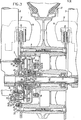
- a hub 8 of the wheel 2f is supported through two bearings 11 on an axle 10.
- the axle 10 is secured to the lower ends of a front fork 9.
- Each of the brakes 3f includes a brake disc 12 securely fixed to the end face of the hub 8 and a brake caliper 14 straddling the disc 12 and supported by a bracket 13 to the front fork 9.
- the caliper 14 operates to grip the brake disc 12 when tne output or nyaraulic pressure trom the cylinder 5f is supplied to the input port 14a. In this way, a braking force -is applied to the wheel 2f.
- the antilock controller 7 is functionally interposed in the hydraulic conduit 15 coupled between the output port 5fa of the cylinder 5f and the input port 14a of the caliper 14.
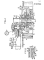
- the controller 7 includes within a common casing 22 a hydraulic pump 16 driven by the wheel 2f, a modulator 17 having a hydraulic control chamber 18 to receive the discharge pressure of the pump 16 and a normally closed exhaust pressure valve 20 interposed in a passage between the chamber 18 and a reservoir 19. Also contained within the casing 22 is an inertia type angular deceleration sensor 21 which controls the valve 20 to release pressure from the braking system when conditions of locking of the wheel 2f are first sensed.
- the pump 16 includes a camshaft 26 arranged parallel to and laterally displaced from the axle 10.
- a pushrod 27 is arranged with its inner end following on the cam surface 26a formed on the camshaft 26.
- a pump piston 28 is actuated by the outer end of the pushrod 27 which is in turn in contact with an operating piston-29.
- a return spring 30 is arranged to bias the rod 27 away from the cam surface 26a.
- the inlet chamber 31 communicates with the fluid reservoir 19 through a conduit 37. This chamber 31 further communicates through a suction valve 38 with the pump chamber 35. The pump chamber 35 in turn communicates with the outlet chamber 32 through a unidirectional sealing member 39. The sealing member 39 provides a discharge valve function.
- the hydraulic chamber 36 is connected to the upstream conduit 15a of the conduit 15 extending between the master cylinder 5f and the calipers 14. The chamber 36 is thus always in communication with the output port 5fa of the cylinder 5f.
- the camshaft 26 is supported in the cover 22b through bearings 40 and 40'.
- This camshaft 26 is driven through a transmission consisting of a pair of gears 43 aid 44.
- the gear 43 is in turn coupled to a drive shaft 42 rotatably supported through bearings 41 about the shaft 24.
- the i shaft 42 is driven by the wheel 2f through a gear unit 45 which
- a meter drive gear 49 is arranged at the opposite end of the camshaft 26 from the gear 44.
- the meter drive gear 49 is engaged with a gear 50 which is in turn connected to the input shaft of a speedometer 51 of the vehicle.
- the modulator 17 includes a pressure reducing piston 46, a stationary piston 47 abutting one end of the pressure reducing piston 46 to restrict the backward movement thereof, and a return spring 48 for biasing the piston 46 into contact with the piston 47.
- Both the pressure reducing piston 46 and the stationary piston 47 are slidably disposed within a second cylindrical hole 52 which is formed adjacent the first cylindrical hole 33 in the cover 22b.
- the piston 46 and the hole 52 define the control hydraulic chamber 18 at one end of the hole 52. Additionally, an output hydraulic chamber 55 is defined within the hole 52 against the piston 47.
- an input hydraulic chamber 54 is arranged which communicates with the chamber 36 of the pump 16 through an oil passage 56.
- the output hydraulic chamber 55 is in communication with the downstream conduit 15b of the conduit 15 between the master cylinder 5f and the brake.
- the conduit 15b is in communication with the input ports 14a of the brakes 3f.
- the control hydraulic chamber 18 communicates with the outlet chamber 32 of the pump 16 through an oil passage 57.
- the piston 47 has a valve chamber 58 which is formed therein. This valve chamber 58 is always in communication with the input hydraulic chamber 54.
- the piston 47 also includes a valve port 59 for communication between the valve chamber 58 and the output hydraulic chamber 55.
- a spherical valve body 60 is positioned within the valve chamber 58 to control communication through the valve port 59.
- a valve spring 61 biases the valve body 60 to the closed position at the port 59.
- a valve opening rod 62 controls the valve body 60. This opening rod extends from one end of the pressure reducing piston 46 and maintains the valve body 60 in the open state when the piston 46 is disposed at its retracted limit within the hole 52.
- the outer end of the second cylindrical hole 52 is closed by an end plate 63.
- This end plate is fixed to the cover 22b.
- the piston 47 extends into contact with the end plate 63 by the resilient force of the spring 48 or by the hydraulic pressure introduced into the chambers 54 and 55.
- the pump 16 and the modulator 17 are disposed on the back side of the front fork 9 in a similar arrangement to that of the caliper 14. This provides protection for the mechanism by being located rearwardly of the front fork against objects and other external conditions encountered through forward motion of the vehicle.
- the wheel angular deceleration sensor 21 includes the accelerating gear unit 45 deriving input from the front wheel 2f.
- a flywheel 72 is rotated by the gear unit 45.
- a cam mechanism 73 is employed for converting the overrunning rotation of the flywheel 72 under certain braking conditions into an axial displacement.
- an output lever mechanism 74 controls operation of the valve 20 in response to the axial displacement of the cam mechanism 73 responsive to the overrunning of the flywheel 72.
- the gear unit 45 is arranged outside of the main wall of the housing 22a as can be seen in Figure 3.
- the cam mechanism 73, the flywheel 72 and the lever mechanism 74 are disposed within the housing 22a.
- one of the gears or sets of gears of the gear unit 45 is preferably formed of a material which will break upon a predetermined level of torque.
- the planetary gear 78 is formed of a synthetic resin material providing that function.
- the synthetic resin material of the gear also provides a buffering effect to reduce the noise of the planetary gear system and to absorb the inertial shock loading of the flywheel 72.
- the gear unit 45 is disposed in the hub 8, further noise reduction is accomplished by the hub itself. Thus, reduction of operating noise and improved durability of the transmission mechanism for the flywheel 72 may be realized.
- the cam plate 82 is generally arranged relative to the cam plate 83 such that a ball within the recesses 82a and 83a is located in the deepest portion of both recesses. In this position, rotary torque received from the shaft 42 by the cam plate 82 is transmitted to the cam plate 83. Under these conditions, no relative rotation occurs between the cam plates 82 and 83.
- the flywheel 72 includes a hub 72a which is rotatably and slidably supported through a bushing 86 on the driveshaft 42.
- the cam plate 83 is rotatably supported on the hub 72a and is engaged with one side of the flywheel 72 through a friction clutch plate 87.
- a pressure plate 89 is provided through a thrust bearing 88 on the other side of the flywheel 72. This arrangement may be best illustrated through reference to both Figures 3 and 5.
- the lever-mechanism 74 includes a supporting shaft 90 which projects from the inner surface of the cover 22b at an intermediate position between the axle 10 and the valve 20.
- a lever 91 is loosely supported in the axial direction of the axle 10 at a neck 90a at the end of the shaft 90.
- a predetermined clearance or play 92 is provided in the axial direction between the neck 90a and the lever 91.
- the lever 91 is composed of a long first arm 91a as illustrated in Figures 2 and 3 which extends around the shaft 42 from the supporting shaft 90.
- a short second arm 91b extends from the shaft 90 toward the valve 20. Midway on the arm 91a, a portion thereof is raised to define an abutment portion 93 which abuts against the outside surface of the plate 89.
- a spring 94 is interposed in a compressed state between the end of the arm 91a and the cover 22b because the arm 91 abuts against the plate 89.
- the arm 91b as a consequence of this arrangement, is held against the outer end of the valve body 67 of the valve 20.
- the resilient force of the spring 94 acts on the lever 91 to press the abutment portion 93 of the arm 91a against the plate 89 which in turn presses the arm 91b against the valve body 67 of the valve 20 to hold the valve body 67 in a closed state.
- the resulting force of the spring 94 acting through the lever 91 is also applied to the flywheel 72, the clutch plate 87 and the cam plate 83 through the plate 89 with a predetermined frictional engagement force. This force acts to press the plates 82 and 83 toward one another.
- the frictional engaging force is set such that the clutch plate slips when the rotary torque between the cam plate 83 and the flywheel 72 exceeds a predetermined level.
- a detector 95 for detecting the normal operation of the lever mechanism 74 is connected to the lever mechanism.
- the detector 95 comprises a switch holder 96 secured to the cover 22b and protruding into the center of the coil of the spring 94.
- a reed switch 97 held by the holder 96 in the coil of the spring 94, a permanent magnet 98 attached to the arm 91a adjacent the switch 97 and a displaced circuit 99 connected to the switch 97 are arranged such that when the arm 91a is rocked by a predetermined angle relative to the cover 22b, the magnet 98 is displaced to close the position of the switch 97.
- the hydraulic pressure output is transmitted sequentially through the upstream conduit 15a of the conduit 1 5 , the chamber 36 of the pump 16, the chamber 54 of the modulator 17, the chamber 58, the valve port 59, the chamber 55 and the downstream conduit 15b of the conduit 15 to the front brake 3f. Braking force is thus applied to the wheel 2f.
- the output hydraulic pressure of the master cylinder 5f is introduced to the chamber 36.
- the pump piston 28 is reciprocated by the action of the hydraulic pressure on the piston 29 and the lifting action of the push rod 27 responsive to the cam surface 26a.
- the valve 38 is opened and the oil from the reservoir is sucked through the conduit 37 and the chamber 31 to the chamber 35.
- the sealing member 39 opens to feed the hydraulic fluid in the chamber 35 to the chamber 32 and further through the oil passage 57 to the chamber 18 of the modulator 17.
- the flywheel 72 senses the deceleration and tends to overrun the driveshaft 42 by the stored inertial force in the flywheel 72.
- the relative movement of the flywheel 72 under this condition produces relative rotation between the cam plates 82 and 83 to axially displace the flywheel 72 by the thrust generated by the rolling of the ball 84.
- the plate 89 is forced axially to push the lever 91.
- the motion of the lever 91 in response to movement of the plate 89 first acts to overcome the play 92 between the shaft 90 and lever 91. If the axial motion continues, the lever 91 is pressed by the plate 89 to rock about the valve body 67 serving as a fulcrum. When the rocking motion of the lever 91 advances to a predetermined degree, the play 92 between the shaft 90 and the lever 91 is eliminated and the fulcrum of the lever moves from the valve body 67 to the shaft 90 which is closer to the advancing plate 89. Up until the fulcrum of the lever 91 is moved to the shaft 90, the motion of the device does not result in any operative change.
- the valve 20 When the valve 20 opens, the hydraulic pressure in the chamber 18 is exhausted through the passage 70, the chamber 68, the port 66, the chamber 69, the passage 71, the chamber 31 of the pump 16 and the conduit 37 to the reservoir 19. Consequently, the piston 46 is returned by the hydraulic pressure of the chamber 55 toward the chamber 18 against the tension of the spring 48. As a result, the rod 62 is retracted to close the valve body 60. The valve body 60 then interrupts the communication between the chambers 54 and 55 and increases the volume of the chamber 55. The brake hydraulic pressure acting on the brake 3f then decreases to reduce the brake force of the wheel 2f. The reduction in the brake force results in the avoidance of locking.
- valve 20 is able to close.
- valve 20 closes the hydraulic oil discharged from the pump 16 is immediately sealed in the chamber 18.
- the piston 46 then retracts toward the chamber 55 to raise the hydraulic pressure in the chamber 55.
- This operation is repeated at high frequency if possibility of locking continues to be exhibited. As a result, average brake force is reduced to the point that effective braking of the wheel 2f can occur.
- the flywheel 72 of the antilock controller 7 and the gear unit 45 are arranged in the hollow portion of the hub 8 which would otherwise be a wasted space. Consequently, the space in the hub may be effectively utilized as a means for providing a compact braking device. Furthermore, the flywheel 72 and the gear unit 45 can be protected through the placement of the system within the hub 8 from adverse external conditions. Since the transmission for operatively connecting the flywheel 72 and the wheel 2f is constructed to include the gear unit 45, the flywheel 72 can be lighter in weight and provide a large inertial force through high-speed rotation of a light flywheel 72 sized to fit within the restricted hollow portion of the hub 8.
- the pump 16 since the pump 16, the modulator 17 and the valve 20 are provided in the cover 22b arranged at the inlet of the hub recess 8a, the piping to the additional components of the braking system is facilitated. In the design of the preferred embodiment, care has been taken to ensure easy disassembly of the gear unit 45 such that the flywheel 72-may be easily removed for improved maintenance efficiency.
- the axial width of the antilock controller 7 can be maintained at a minimum, making possible the containment of the mechanism within the hub 8.
- the front fork 9 is forced backward by the braking force of the vehicle. Naturally, when this braking force is released, the resiliency of the front fork 9 causes it to move forwardly relative to the vehicle.
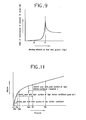
- a frequency of vibration is experienced in the braking force to the front fork 9. It has been determined that the sensor 21 loses its effectiveness when it operates at a frequency near the resonance of the front fork 9 in its fore and aft movement responsive to braking force.
- Figure 9 illustrates the resonance curve responsive to variation in the frequency of operation of the sensor 21. As is apparent from Figure 9, the transmission of vibration to the sensor 21 abruptly increases when the frequency of operation of the sensor 21 approaches the natural frequency of the fork. It may also be observed from Figure 9 that the transmission of vibration decreases when the natural frequency f l is exceeded but not below a minimum value.
- the preferred embodiment of the present invention provides a sensor 21 having a frequency F O intentionally set to be significantly lower than the natural frequency F 1 of the front fork 9. As a result, even if the drive shaft 42 is vibrated by the wheel 2f, the sensor 21 receives only a small amount of vibration and interference with the performance of the sensor 21 is reduced.
- FIG. 8 illustrates a second embodiment of the present invention.
- a gear unit 45 is constructed in the same manner as that of the first embodiment of the invention with the exception that a ring gear 76 is formed on an input member 111 which is driven through axially interlocking surfaces such as radial splines 110 by a hub 8.
- the gear unit 45 includes the annular gear 76, planetary gears 78 supported on shafts 77 on a carrier 112 and additional corresponding components to those of the first embodiment. Same reference numerals are employed in this second embodiment as on the first embodiment.
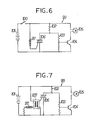
- Figure 10 illustrates a third embodiment of the present invention.
- a second rear wheel brake 3r' is provided and a proportional pressure reducing valve 114 is interposed in a connecting conduit 113 between the input port of the brake 3r' and a front master cylinder 5f.
- the valve 114 may be of a conventional type adapted for proportionally reducing the hydraulic pressure at the input side to transmit a reduced pressure to the output side.
- the conduit 113 is in communication with the upstream conduit 15a of the hydraulic conduit 15.
- a hydraulic conduit 115 extends from the output port of the rear master cylinder 5r and is connected to the input port of the first brake 3r. The brake 3r operates only when the cylinder 5r is operated.
- the braking characteristics of the front wheel depend upon the pressure volume characteristic of the front wheel brake when an antilock controller employing angular deceleration sensors driven by a front wheel controls hydraulic braking pressure.
- the pressure volume characteristic as can be seen in Figure 11, is generally not proportional. Rather, the relationship of volume to pressure generally varies greatly in the low pressure range and varies less greatly in the high pressure range.
- the antilock controller To satisfy the antilock performance with an acceptable braking feeling on road surfaces having a high coefficient of friction, it is preferable to operate the antilock controller well into the high pressure range with less volumetric change.
- FIGS 12 and 13 illustrate a fourth embodiment of the present invention.
- the front and rear wheel brakes 3f and 3r can be simultaneously actuated by the operation of the rear master cylinder 5r.
- the upstream conduit 15a of the hydraulic conduit 15 is placed in communication with the output port of the rear master cylinder 5r.
- a relay master cylinder 5m is interposed in the conduit 15a.
- This relay master cylinder 5m comprises a cylinder body 122 including an oil reservoir 121 and a stepped piston 124 slidably fitted in a cylindrical hole 123 of the cylinder body 122.
- the stepped piston 124 partitions the interior of the cylindrical hole 123 into first and second hydraulic input chambers 125a and 125b arranged in parallel.
- a hydraulic output chamber 126 is opposed to the first and second input hydraulic chambers 125a and 125b.
- the upstream side of the conduit 15a extending from the output port of the master cylinder 5r is connected to the first input hydraulic chamber 125a and the downstream side of the conduit 15a in communication with the antilock controller 7 is connected to the output hydraulic chamber 126.
- a hydraulic conduit 119 extending from the output port of the master cylinder 5f is connected to the second input hydraulic chamber 125b.
- One rear wheel brake 3r is provided.
- a conduit 120 in communication with the conduit 15a is connected to the brake 3r.
- a proportional pressure reducing valve 114 is interposed in the conduit 120. Otherwise, the construction remains the same as that of the third embodiment of the present invention.
- the hydraulic output pressure is introduced to the first input hydraulic chamber 125a of the relay master cylinder 5m. This moves the piston 124 forward generating greater hydraulic pressure in the chamber 126. The hydraulic pressure is then transmitted through the controller 7 to the brakes 3f. The output hydraulic pressure of the master cylinder 5r is also transmitted through the valve 114 to the brake 3r to simultaneously operate the front and rear brakes. Thus, brake forces are simultaneously applied to the front and rear wheels 2f and 2r by the operation of the master cylinder 5r. Simultaneously, the hydraulic brake pressure to the brake 2f is controlled by the controller 7 in the same manner as in the first embodiment of the present invention.
- the rear brake can be simultaneously operated when the front brake is operated.
- the effect of this operation is that the ground load to the front wheel is increased at braking.
- the operating range of the antilock controller is thus shifted to the high pressure side at braking on road surfaces having high coefficients of friction.
- the variation in volume of the hydraulic chamber of the front wheel brake is thus reduced. This results in a decrease in the variation between acceleration and deceleration of the vehicle responsive to the antilock mechanism.
- the brake feeling is improved and the braking efficiency may be enhanced.
Landscapes
- Engineering & Computer Science (AREA)
- Transportation (AREA)
- Mechanical Engineering (AREA)
- Regulating Braking Force (AREA)
Applications Claiming Priority (6)
| Application Number | Priority Date | Filing Date | Title |
|---|---|---|---|
| JP92456/84 | 1984-05-09 | ||
| JP9245684A JPS60236856A (ja) | 1984-05-09 | 1984-05-09 | 車両のアンチロツク制動装置 |
| JP10983284A JPH0239417B2 (ja) | 1984-05-30 | 1984-05-30 | Sharinkakugensokudosensa |
| JP109832/84 | 1984-05-30 | ||
| JP22539784A JPS60236857A (ja) | 1984-10-26 | 1984-10-26 | 二輪車のアンチロツク制動装置 |
| JP225397/84 | 1984-10-26 |
Related Child Applications (1)
| Application Number | Title | Priority Date | Filing Date |
|---|---|---|---|
| EP88109496.5 Division-Into | 1985-05-09 |
Publications (3)
| Publication Number | Publication Date |
|---|---|
| EP0164893A2 true EP0164893A2 (de) | 1985-12-18 |
| EP0164893A3 EP0164893A3 (en) | 1986-11-26 |
| EP0164893B1 EP0164893B1 (de) | 1989-08-09 |
Family
ID=27307048
Family Applications (2)
| Application Number | Title | Priority Date | Filing Date |
|---|---|---|---|
| EP88109496A Expired EP0297351B1 (de) | 1984-05-09 | 1985-05-09 | Antiblockier-Bremsgerät für ein Fahrzeug |
| EP85303278A Expired EP0164893B1 (de) | 1984-05-09 | 1985-05-09 | Antiblockier-Bremsgerät für ein Fahrzeug |
Family Applications Before (1)
| Application Number | Title | Priority Date | Filing Date |
|---|---|---|---|
| EP88109496A Expired EP0297351B1 (de) | 1984-05-09 | 1985-05-09 | Antiblockier-Bremsgerät für ein Fahrzeug |
Country Status (4)
| Country | Link |
|---|---|
| US (1) | US4792194A (de) |
| EP (2) | EP0297351B1 (de) |
| CA (1) | CA1262753A (de) |
| DE (2) | DE3586462T2 (de) |
Cited By (4)
| Publication number | Priority date | Publication date | Assignee | Title |
|---|---|---|---|---|
| GB2200700A (en) * | 1987-02-03 | 1988-08-10 | Lucas Ind Plc | Mounting motor cycle anti-lock hydraulic modulator unit |
| EP0255351A3 (en) * | 1986-07-31 | 1988-09-28 | Lucas Industries Public Limited Company | Improvements in hydraulic anti-skid braking systems for vehicles |
| EP0270379A3 (en) * | 1986-12-04 | 1988-09-28 | Honda Giken Kogyo Kabushiki Kaisha | Wheel angular acceleration sensor for anti-lock controller for vehicles |
| CN105156518A (zh) * | 2015-08-27 | 2015-12-16 | 湖南三一石油科技有限公司 | 一种工程机械及其回转制动系统 |
Families Citing this family (5)
| Publication number | Priority date | Publication date | Assignee | Title |
|---|---|---|---|---|
| US5257856A (en) * | 1991-07-23 | 1993-11-02 | Honda Giken Kogyo Kabushiki Kaisha | Method of and system for controlling brakes |
| US7197383B2 (en) * | 2004-02-17 | 2007-03-27 | Ford Global Technologies, Llc | System for limiting reactive torque in powertrains |
| JP2016203923A (ja) * | 2015-04-28 | 2016-12-08 | ローベルト ボッシュ ゲゼルシャフト ミット ベシュレンクテル ハフツング | ブレーキ液圧制御装置、及び、アンチロックブレーキシステム |
| US11772624B2 (en) | 2021-01-08 | 2023-10-03 | Volvo Truck Corporation | Braking arrangement for a vehicle |
| EP4357152B1 (de) * | 2022-10-19 | 2025-08-20 | Hochschule Für Angewandte Wissenschaften München | Antiblockier-bremssystem |
Family Cites Families (54)
| Publication number | Priority date | Publication date | Assignee | Title |
|---|---|---|---|---|
| US31387A (en) * | 1861-02-12 | Oak-brake | ||
| NL157130B (nl) * | 1949-11-17 | Sony Corp | Magnetische opneem- en/of weergeefinrichting. | |
| US2818244A (en) * | 1954-11-22 | 1957-12-31 | Westinghouse Air Brake Co | Deceleration responsive apparatus |
| GB778765A (en) * | 1955-02-23 | 1957-07-10 | Westinghouse Air Brake Co | Improvements relating to wheel-slip responsive devices for vehicle wheels |
| US2920924A (en) * | 1957-06-17 | 1960-01-12 | Williams | Airplane brake control |
| GB894577A (en) * | 1957-09-05 | 1962-04-26 | Dunlop Rubber Co | Combined brake and anti-skid device |
| GB895294A (en) * | 1957-10-15 | 1962-05-02 | Dunlop Rubber Co | Anti-skid device for vehicle wheels |
| US3046060A (en) * | 1961-06-16 | 1962-07-24 | Francis W Stager | Automobile anti-skid control assembly |
| US3326333A (en) * | 1965-03-08 | 1967-06-20 | Edward A Rockwell | Disc brake with compensation, anti-skid control, and fail-safe system |
| US3667816A (en) * | 1970-02-16 | 1972-06-06 | Gen Motors Corp | Vehicle wheel velocity control system and method |
| US3626225A (en) * | 1970-06-01 | 1971-12-07 | Bendix Corp | Wheel speed sensor for an adaptive braking system having a rotatable tone wheel and electromagnetic pickup means |
| US3731767A (en) * | 1971-05-13 | 1973-05-08 | L Lefort | Braking device including anti-skid means |
| DE2208185A1 (de) * | 1972-02-22 | 1973-08-30 | Bosch Gmbh Robert | Druckmittelbremsanlage mit gleitschutzregelung |
| GB1497707A (en) * | 1975-05-10 | 1978-01-12 | Girling Ltd | Anti-skid hydraulic braking systems for vehicles |
| JPS51141966A (en) * | 1975-05-31 | 1976-12-07 | Honda Motor Co Ltd | Antiskid braking device for vehicles |
| USRE31387E (en) | 1975-08-30 | 1983-09-20 | Girling Limited | Anti-skid vehicle braking system |
| US4046427A (en) * | 1976-06-21 | 1977-09-06 | General Motors Corporation | Mechanical wheel lock control |
| US4110647A (en) * | 1977-01-13 | 1978-08-29 | The Bendix Corporation | Wheel speed sensor |
| DE2731201C2 (de) * | 1977-07-11 | 1983-12-08 | Alfred Teves Gmbh, 6000 Frankfurt | Druckmittel-Bremssystem für Motorräder |
| JPS5450763A (en) * | 1977-09-15 | 1979-04-20 | Girling Ltd | Hydraulic antiiskid brake system |
| AU529107B2 (en) * | 1977-11-01 | 1983-05-26 | Ivar Blomberg Folke | Sensor for braking systems |
| SE409973B (sv) * | 1978-01-30 | 1979-09-17 | Blomberg Folke Ivar | Sensor for overvakning av retardation eller acceleration hos ett roterande organ |
| JPS554250A (en) * | 1978-06-24 | 1980-01-12 | Yamaha Motor Co Ltd | Motorcycle |
| DE2830384C3 (de) * | 1978-07-11 | 1981-10-29 | Adlerwerke Vorm. Heinrich Kleyer Ag, 6000 Frankfurt | Reiterschiene für Schreibmaschinen |
| GB2107015B (en) * | 1978-08-18 | 1983-08-17 | Lucas Industries Ltd | Improvements in anti-skid braking systems for vehicles |
| IT1122761B (it) * | 1978-08-18 | 1986-04-23 | Lucas Industries Ltd | Perfezionamenti nei sistemi di frenatura idraulici anti scivolamento per veicoli |
| DE2838152A1 (de) * | 1978-09-01 | 1980-03-13 | Bosch Gmbh Robert | Servolenkung |
| US4281881A (en) * | 1978-09-05 | 1981-08-04 | The Budd Company | Anti-locking mechanism |
| JPS5545421A (en) * | 1978-09-27 | 1980-03-31 | Shinai Giken Kk | Erecting and folding apparatus of table legs |
| US4225020A (en) * | 1978-10-23 | 1980-09-30 | Blomberg Folke Ivar | Braking arrangement with rotational rate of change sensor |
| US4210369A (en) * | 1978-12-11 | 1980-07-01 | Curnutt Charles R | Anti-lock power brake |
| JPS55114648A (en) * | 1979-02-06 | 1980-09-04 | Lucas Industries Ltd | Hydraulic pressure actuating antiskiddbrake system |
| JPS55119547A (en) * | 1979-02-23 | 1980-09-13 | Lucas Industries Ltd | Nonnskid brake control system |
| US4381049A (en) * | 1979-07-30 | 1983-04-26 | Goodyear Aerospace Corporation | Electrically actuated aircraft brakes |
| DE3030621A1 (de) * | 1979-08-14 | 1981-03-26 | Lucas Industries Ltd., Birmingham, West Midlands | Hydraulische bremsanlage mit blockierschutzeinrichtung fuer fahrzeuge |
| GB2074276B (en) * | 1979-09-18 | 1983-09-21 | Lucas Industries Ltd | Wheel slide protection system |
| JPS5648942U (de) * | 1979-09-21 | 1981-04-30 | ||
| GB2070166A (en) * | 1980-01-30 | 1981-09-03 | Lucas Industries Ltd | Improvements in Anti-skid Braking Systems for Vehicles |
| GB2071242B (en) * | 1980-02-07 | 1983-09-14 | Lucas Industries Ltd | Hydraulically-operated anti-skid braking systems for vehicles |
| EP0034449B1 (de) * | 1980-02-16 | 1984-01-25 | LUCAS INDUSTRIES public limited company | Hydraulisch betätigte Gleitschutzbremssysteme für Fahrzeuge |
| GB2069642B (en) * | 1980-02-16 | 1984-05-02 | Lucas Industries Ltd | Rotary flywheel anti-skid braking systems |
| GB2069641A (en) * | 1980-02-16 | 1981-08-26 | Lucas Industries Ltd | Improvements in flywheel mechanisms for fluid-pressure operated anti-skid braking systems |
| US4414630A (en) * | 1980-03-19 | 1983-11-08 | Lucas Industries Limited | Anti-skid vehicle braking systems |
| DE3015729A1 (de) * | 1980-04-24 | 1981-10-29 | Daimler-Benz Ag, 7000 Stuttgart | Bremsventil, das in verbindungen mit einer blockierschutzueberwachten fahrzeugbremsanlage verwendbar ist |
| GB2079389B (en) * | 1980-07-08 | 1984-08-22 | Lucas Industries Ltd | Anti-skid braking systems for vehicles |
| JPS5733052A (en) * | 1980-08-05 | 1982-02-23 | Honda Motor Co Ltd | Skid control device |
| DE3048182A1 (de) * | 1980-12-19 | 1982-08-26 | VMEI Lenin, Sofia | Verfahren und vorrichtung zur erzeugung eines antiblockiereffekts beim abbremsen der raeder eines transportmittels |
| EP0056130B1 (de) * | 1981-01-08 | 1985-06-05 | Niveau AG | Gleitschutzvorrichtung für bereifte, insbesondere luftbereifte Fahrzeugräder für Eis- und Schneeflächen |
| GB2101246B (en) * | 1981-01-14 | 1985-02-27 | Lucas Industries Ltd | Improvements in anti-skid hydraulic braking systems for vehicles |
| GB2101245B (en) * | 1981-01-14 | 1985-02-27 | Lucas Industries Ltd | Improvements in anti-skid hydraulic braking systems for vehicles |
| US4436348A (en) * | 1981-10-13 | 1984-03-13 | Lucas Industries Public Limited Company | Anti-skid hydraulic braking systems for vehicles |
| GB2109494B (en) * | 1981-11-09 | 1985-08-07 | Lucas Ind Plc | Flywheel mechanisms for anti-skid braking systems |
| GB2109069B (en) * | 1981-11-09 | 1985-08-07 | Lucas Industries Ltd | Modulators in hydraulic anti-skid braking systems for vehicles |
| US4551156A (en) * | 1984-01-16 | 1985-11-05 | Standard Oil Company | Permselective membrane compositions for gas separations and process for the separation of gases therewith |
-
1985
- 1985-05-08 CA CA000481054A patent/CA1262753A/en not_active Expired
- 1985-05-09 DE DE8888109496T patent/DE3586462T2/de not_active Expired - Fee Related
- 1985-05-09 DE DE8585303278T patent/DE3572144D1/de not_active Expired
- 1985-05-09 EP EP88109496A patent/EP0297351B1/de not_active Expired
- 1985-05-09 EP EP85303278A patent/EP0164893B1/de not_active Expired
-
1987
- 1987-02-13 US US07/015,557 patent/US4792194A/en not_active Expired - Fee Related
Cited By (5)
| Publication number | Priority date | Publication date | Assignee | Title |
|---|---|---|---|---|
| EP0255351A3 (en) * | 1986-07-31 | 1988-09-28 | Lucas Industries Public Limited Company | Improvements in hydraulic anti-skid braking systems for vehicles |
| EP0270379A3 (en) * | 1986-12-04 | 1988-09-28 | Honda Giken Kogyo Kabushiki Kaisha | Wheel angular acceleration sensor for anti-lock controller for vehicles |
| GB2200700A (en) * | 1987-02-03 | 1988-08-10 | Lucas Ind Plc | Mounting motor cycle anti-lock hydraulic modulator unit |
| GB2200700B (en) * | 1987-02-03 | 1991-02-13 | Lucas Ind Plc | Improvements in anti-lock hydraulic modulator units for vehicles |
| CN105156518A (zh) * | 2015-08-27 | 2015-12-16 | 湖南三一石油科技有限公司 | 一种工程机械及其回转制动系统 |
Also Published As
| Publication number | Publication date |
|---|---|
| DE3572144D1 (en) | 1989-09-14 |
| EP0164893B1 (de) | 1989-08-09 |
| CA1262753A (en) | 1989-11-07 |
| DE3586462T2 (de) | 1993-03-18 |
| DE3586462D1 (de) | 1992-09-10 |
| EP0297351A1 (de) | 1989-01-04 |
| EP0164893A3 (en) | 1986-11-26 |
| US4792194A (en) | 1988-12-20 |
| EP0297351B1 (de) | 1992-08-05 |
Similar Documents
| Publication | Publication Date | Title |
|---|---|---|
| US4697825A (en) | Anti-lock braking system for the front wheel of a motorcycle | |
| EP0344817B1 (de) | Antiblockier-Bremsgerät für Fahrzeuge | |
| GB2160937A (en) | Antilock braking system arrangement | |
| EP0297351B1 (de) | Antiblockier-Bremsgerät für ein Fahrzeug | |
| US4770473A (en) | Brake device for vehicles | |
| US4852701A (en) | Rear wheel braking system for motorcycle | |
| EP0270379B1 (de) | Radwinkelbeschleunigungssensor für Blockierverhinderer von Fahrzeugen | |
| US4745994A (en) | Angular deceleration sensor | |
| EP0268394B1 (de) | Beschleunigungssensor für Blockierverhinderer von Fahrzeugbremsen | |
| JPH048264B2 (de) | ||
| JPS6181859A (ja) | 車両のアンチロツク制御装置 | |
| JPS60236857A (ja) | 二輪車のアンチロツク制動装置 | |
| JPS6237260A (ja) | 車両用アンチロツク制御装置 | |
| JPS6181856A (ja) | 車両のアンチロツク制動装置 | |
| JPH0239417B2 (ja) | Sharinkakugensokudosensa | |
| JPH0355338B2 (de) | ||
| JPS60252053A (ja) | アンチロツク制御装置のモジユレ−タ | |
| JPS60244661A (ja) | 車両のアンチロツク制御装置 | |
| JPS60244662A (ja) | 車両のアンチロツク制動装置 | |
| JPS6181857A (ja) | 車両のアンチロツク制動装置 | |
| JPS6181855A (ja) | 車両のアンチロツク制動装置 | |
| JPS60236856A (ja) | 車両のアンチロツク制動装置 | |
| JPS61181757A (ja) | 車輪角加速度センサの駆動装置 | |
| JPH034414B2 (de) | ||
| JPS61181756A (ja) | 車輪角加速度センサの駆動装置 |
Legal Events
| Date | Code | Title | Description |
|---|---|---|---|
| PUAI | Public reference made under article 153(3) epc to a published international application that has entered the european phase |
Free format text: ORIGINAL CODE: 0009012 |
|
| AK | Designated contracting states |
Designated state(s): DE FR GB IT |
|
| PUAL | Search report despatched |
Free format text: ORIGINAL CODE: 0009013 |
|
| AK | Designated contracting states |
Kind code of ref document: A3 Designated state(s): DE FR GB IT |
|
| 17P | Request for examination filed |
Effective date: 19870126 |
|
| 17Q | First examination report despatched |
Effective date: 19871008 |
|
| GRAA | (expected) grant |
Free format text: ORIGINAL CODE: 0009210 |
|
| AK | Designated contracting states |
Kind code of ref document: B1 Designated state(s): DE FR GB IT |
|
| ITF | It: translation for a ep patent filed | ||
| REF | Corresponds to: |
Ref document number: 3572144 Country of ref document: DE Date of ref document: 19890914 |
|
| ET | Fr: translation filed | ||
| PLBE | No opposition filed within time limit |
Free format text: ORIGINAL CODE: 0009261 |
|
| STAA | Information on the status of an ep patent application or granted ep patent |
Free format text: STATUS: NO OPPOSITION FILED WITHIN TIME LIMIT |
|
| 26N | No opposition filed | ||
| PGFP | Annual fee paid to national office [announced via postgrant information from national office to epo] |
Ref country code: FR Payment date: 19910522 Year of fee payment: 7 |
|
| ITTA | It: last paid annual fee | ||
| PGFP | Annual fee paid to national office [announced via postgrant information from national office to epo] |
Ref country code: DE Payment date: 19910531 Year of fee payment: 7 |
|
| PGFP | Annual fee paid to national office [announced via postgrant information from national office to epo] |
Ref country code: GB Payment date: 19920429 Year of fee payment: 8 |
|
| PG25 | Lapsed in a contracting state [announced via postgrant information from national office to epo] |
Ref country code: FR Effective date: 19930129 |
|
| PG25 | Lapsed in a contracting state [announced via postgrant information from national office to epo] |
Ref country code: DE Effective date: 19930202 |
|
| REG | Reference to a national code |
Ref country code: FR Ref legal event code: ST |
|
| PG25 | Lapsed in a contracting state [announced via postgrant information from national office to epo] |
Ref country code: GB Effective date: 19930509 |
|
| GBPC | Gb: european patent ceased through non-payment of renewal fee |
Effective date: 19930509 |