EP0162183A1 - Verfahren zum Zusammensetzen dreidimensionaler Strukturen aus Metalldraht, und Maschine zur Durchführung des Verfahrens - Google Patents
Verfahren zum Zusammensetzen dreidimensionaler Strukturen aus Metalldraht, und Maschine zur Durchführung des Verfahrens Download PDFInfo
- Publication number
- EP0162183A1 EP0162183A1 EP84870056A EP84870056A EP0162183A1 EP 0162183 A1 EP0162183 A1 EP 0162183A1 EP 84870056 A EP84870056 A EP 84870056A EP 84870056 A EP84870056 A EP 84870056A EP 0162183 A1 EP0162183 A1 EP 0162183A1
- Authority
- EP
- European Patent Office
- Prior art keywords
- wires
- spacer
- longitudinal
- welding
- trellis
- Prior art date
- Legal status (The legal status is an assumption and is not a legal conclusion. Google has not performed a legal analysis and makes no representation as to the accuracy of the status listed.)
- Granted
Links
- 238000000034 method Methods 0.000 title claims abstract description 31
- 239000002184 metal Substances 0.000 title claims abstract description 7
- 229910052751 metal Inorganic materials 0.000 title claims abstract description 7
- 125000006850 spacer group Chemical group 0.000 claims abstract description 76
- 238000003466 welding Methods 0.000 claims abstract description 73
- 238000004519 manufacturing process Methods 0.000 claims abstract description 8
- 238000006073 displacement reaction Methods 0.000 claims description 7
- 238000005520 cutting process Methods 0.000 claims description 6
- 238000001816 cooling Methods 0.000 claims description 3
- 230000000694 effects Effects 0.000 claims description 2
- 230000009466 transformation Effects 0.000 claims description 2
- 230000006835 compression Effects 0.000 claims 1
- 238000007906 compression Methods 0.000 claims 1
- 238000000151 deposition Methods 0.000 claims 1
- 238000012795 verification Methods 0.000 claims 1
- 238000010586 diagram Methods 0.000 description 5
- 238000010276 construction Methods 0.000 description 2
- 230000005484 gravity Effects 0.000 description 2
- 238000011084 recovery Methods 0.000 description 2
- 230000000717 retained effect Effects 0.000 description 2
- 238000005476 soldering Methods 0.000 description 2
- 230000003068 static effect Effects 0.000 description 2
- 230000001360 synchronised effect Effects 0.000 description 2
- RYGMFSIKBFXOCR-UHFFFAOYSA-N Copper Chemical compound [Cu] RYGMFSIKBFXOCR-UHFFFAOYSA-N 0.000 description 1
- 229910000831 Steel Inorganic materials 0.000 description 1
- 229910052802 copper Inorganic materials 0.000 description 1
- 239000010949 copper Substances 0.000 description 1
- 239000011810 insulating material Substances 0.000 description 1
- 238000003825 pressing Methods 0.000 description 1
- 229910000679 solder Inorganic materials 0.000 description 1
- 239000010959 steel Substances 0.000 description 1
Images


Classifications
-
- E—FIXED CONSTRUCTIONS
- E04—BUILDING
- E04C—STRUCTURAL ELEMENTS; BUILDING MATERIALS
- E04C5/00—Reinforcing elements, e.g. for concrete; Auxiliary elements therefor
- E04C5/01—Reinforcing elements of metal, e.g. with non-structural coatings
- E04C5/06—Reinforcing elements of metal, e.g. with non-structural coatings of high bending resistance, i.e. of essentially three-dimensional extent, e.g. lattice girders
-
- B—PERFORMING OPERATIONS; TRANSPORTING
- B21—MECHANICAL METAL-WORKING WITHOUT ESSENTIALLY REMOVING MATERIAL; PUNCHING METAL
- B21F—WORKING OR PROCESSING OF METAL WIRE
- B21F27/00—Making wire network, i.e. wire nets
- B21F27/08—Making wire network, i.e. wire nets with additional connecting elements or material at crossings
- B21F27/10—Making wire network, i.e. wire nets with additional connecting elements or material at crossings with soldered or welded crossings
-
- B—PERFORMING OPERATIONS; TRANSPORTING
- B21—MECHANICAL METAL-WORKING WITHOUT ESSENTIALLY REMOVING MATERIAL; PUNCHING METAL
- B21F—WORKING OR PROCESSING OF METAL WIRE
- B21F27/00—Making wire network, i.e. wire nets
- B21F27/12—Making special types or portions of network by methods or means specially adapted therefor
- B21F27/121—Making special types or portions of network by methods or means specially adapted therefor of tubular form, e.g. as reinforcements for pipes or pillars
-
- B—PERFORMING OPERATIONS; TRANSPORTING
- B21—MECHANICAL METAL-WORKING WITHOUT ESSENTIALLY REMOVING MATERIAL; PUNCHING METAL
- B21F—WORKING OR PROCESSING OF METAL WIRE
- B21F27/00—Making wire network, i.e. wire nets
- B21F27/12—Making special types or portions of network by methods or means specially adapted therefor
- B21F27/128—Making special types or portions of network by methods or means specially adapted therefor of three-dimensional form by connecting wire networks, e.g. by projecting wires through an insulating layer
-
- B—PERFORMING OPERATIONS; TRANSPORTING
- B23—MACHINE TOOLS; METAL-WORKING NOT OTHERWISE PROVIDED FOR
- B23K—SOLDERING OR UNSOLDERING; WELDING; CLADDING OR PLATING BY SOLDERING OR WELDING; CUTTING BY APPLYING HEAT LOCALLY, e.g. FLAME CUTTING; WORKING BY LASER BEAM
- B23K11/00—Resistance welding; Severing by resistance heating
- B23K11/002—Resistance welding; Severing by resistance heating specially adapted for particular articles or work
- B23K11/008—Manufacturing of metallic grids or mats by spot welding
Definitions
- the invention relates to a method of assembling three-dimensional metal structures, by way of example for prefabricated elements such as panels or ceilings to be used in construction.
- the invention also relates to the machines which carry out this process and, finally, to the structure produced according to this same process.
- a three-dimensional structure of metal wires comprising a series of planar trellises. Each trellis is provided with at least one pair of longitudinal wires and spacer wires. The trellises have predetermined reciprocal distances thanks to a series of transverse wires welded to the trellises themselves and to strut wires.
- Such a structure forms support planes for elongated bodies of corresponding dimensions made of inserted light and insulating material. inside the structure itself.
- the production of these structures requires very little tolerance of the different components and meticulous alignment between these parts during the welding phases. To meet these requirements, numerous manual interventions to carry the welding units to the crossing zones of the solder wire and to maintain alignment between the parts are required. Such a process is therefore necessarily expensive.
- the three-dimensional structure produced according to the method according to the invention is characterized by a remarkable resistance to stresses, thanks to the twist of the wires and to the precision of the welds.
- This structure is further characterized by an accuracy in the planes of the different spacer wires, in order to obtain very reduced spaces between the elongated bodies inserted inside the structure itself.
- the assembled structure has great dimensional precision in order to guarantee an optimal arrangement of the panels during construction.
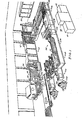
- the assembly method according to the invention is intended to produce, for example but not exclusively, three-dimensional metallic structures 30 (FIG. 2) of the kind described in European patent application No. 82102021 published on September 29, 82.
- the aim of this process is, in particular, to assemble plane trellises 36 made of steel wires with transverse wires 37 and preferably provides for the use of a machine allowing the three-dimensional structure 40 to be assembled.
- the lattice 36 comprises son longitudinal strut 34 and 35 and son are at an earlier stage than that of assembling the three-dimensional structure achieved s by means of a plate welder 38 (figure 1).
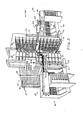
- the assembly machine 40 (FIG. 2) comprises a support structure 41 which supports the mesh 36, a feed group 42 from which the transverse wires 37 are taken to be welded to the mesh 36, a series of welding units 43 and a feed group 45 for the structure 30, during the assembly, and a collection assembly 50 (FIG. 1).
- the machine also provides an electronic group 57 (FIG. 10) for the sequential control of the various assembly and welding phases, a control console 58, a pneumatic unit 59 for carrying out the commands or orders sent by the unit 58 and a hydraulic unit 60 for cooling the welding electrodes of the assembly machines 38 and 40.
- an electronic group 57 (FIG. 10) for the sequential control of the various assembly and welding phases
- a control console 58 for the sequential control of the various assembly and welding phases
- a pneumatic unit 59 for carrying out the commands or orders sent by the unit 58
- a hydraulic unit 60 for cooling the welding electrodes of the assembly machines 38 and 40.
- the following description relates to the support structure.
- the support structure 41 comprises a group of uprights 79 on which are fixed at predetermined distances, in pairs, a series of crosspieces 80.
- the crosspieces 80 in turn support a series of horizontal and superimposed support planes 81.
- the distances between the planes 81 are equal to each other and regulate the transverse pitch of the planar lattice 36 relative to the structure 30 already assembled.
- the planes 81 are of very elongated rectangular shape and are provided with two lateral sides 82 and 83, respectively left and right, if one refers to FIG. 4, and support a trellis corresponding to plane 36.
- a control element 83 formed of a a drawing of rectangular section, is fixed to each side 82 and is provided with a control surface 85 capable of collaborating with the ends, on the left in the figure, of the spacer wires 35 of the trellises 36.
- the surfaces 85 of the control elements 83 of the different planes 81 are located in the same planet define a vertical reference surface of the three-dimensional structure 30.
- Another control element 86 also consisting of a drawing of rectangular section, is fixed, in an adjustable manner to the side 83 of each plane 81 and is provided with a surface 87 with which the ends can collaborate, on the right in the figure. , spacer wires 35 of the trellises 36.
- the surfaces 87 of the control elements 86 are located in the same plane and define another vertical reference plane of the three-dimensional structure 30, parallel to the vertical plane defined by the surfaces 85.
- two reference planes are such that they bring the longitudinal wires 34 in the same plane, on the same side of the different trellises 36 and are, moreover, perpendicular to the planes of the same trellises 36.
- control elements 85 and 86 are fixed guide elements 92 and 93 formed of U- shaped wire sections projecting out of the planes 81. These elements collaborate with the ends of the spacer wires 3 5 as well as q u 'with the longitudinal wires 34 of the planar lattices 36 and serve to define with precision the vertical reference planes of the structure 30 and to avoid warping of the lattices 36 in the area close to the outlet end of the guide elements 92 and 93, adjacent to the welding units 43.
- control elements 87 and the guide elements 93 can be moved relative to the sides 83, for example using screws 94.
- the distance between the reference planes of the surfaces 87 and the guide elements 92 can be modified either with respect to the reference plane of the surfaces 85, or with respect to the guide elements 93, to define exactly the vertical reference planes of the structures 30 using lattices 36 of different widths.
- a feeding group follows on from the support structure.
- This supply group 42 is divided into two units, each of which comprises a hopper 101 (FIG. 2) in which are arranged such as transverse wires 37.
- the wires penetrate by gravity into an outlet channel 102 (FIG. 11) and this operation is facilitated by the action of an eccentric 103.
- a device 104 is arranged for dropping one by one the wires 37 which, after having been guided by the inclined bars 105, stop at the base of the bars 105, abutting against shoulders 106.
- the presence of the wire 37, retained against the shoulders 106 is detected by a magnetic signaler 107 which transmits, in the form of electrical signals, the information in question to the control unit 57.
- each gripping arm III is formed by a parallelepiped bar with a fulcrum at one end and an output shaft 112 of a pneumatic actuator 113.
- This actuator l13 is provided to rotate the gripping arm from a horizontal position to a vertical position.
- Each gripping arm 111 is, in its horizontal position, substantially aligned and superimposed on the wire 37 temporarily stopped against the shoulders 106 and near the wire itself.
- a number of magnets 114 are arranged to separate the wire 37 from the shoulders 106 and to hold it on the arm 111 in alignment with the axis of the same arm.
- Two sensors 115 and 116 also have the task of detecting the horizontal position and the vertical position of the arm 111 respectively and of transmitting the information to the control unit 57.
- two pneumatic operating members 121 Facing the hopper 101 (FIGS. 2 and 3), are arranged two pneumatic operating members 121, provided with pistons 122, movable in a horizontal plane in a direction perpendicular to the reference planes of the surfaces 85 and 86.
- pistons 122 On the pistons 122 are fixed two corresponding support blocks 123 on which are fixed in turn two other pneumatic actuators 124.
- actuators 124 are provided with pistons 125 which are movable horizontally in a direction inclined by 45 ° relative to the reference planes of the surfaces 85 and 86.
- the pistons 125 support two uprights 126 to which are fixed two corresponding series of pliers 127, pneumatically operated, capable of separating the wires 37 from the arms 111 and of holding them parallel to the uprights 126.
- Sensors 128 make it possible to detect the presence of one or more wires 37 retained by the clamps 127.
- the supports 123 can be moved away from the pistons 122 from lateral positions near the hoppers towards central positions close to the welding units 43 and the elements guide 92 and 93.
- the uprights 126 can, in turn, be moved away from the pistons 125 from positions remote from the hoppers 101 and from the guide elements 92 and 93 towards zones close to the arms 111, arranged in a vertical position, and welding units 43.
- End-of-travel sensors 131 and 132 of the operating members 121 respectively detect the lateral and central positions of the blocks 123 and end-of-travel sensors 133 of the operating members 124 detect the positions of the uprights 126 near the arms 111 and the soldering units 43.
- magnetic sensors 134 detect the presence of the wires 37 on the uprights 126, while they are held by clips 127. The information from the sensors 134 is also transmitted to the control unit 57.
- the hoppers 101 are arranged to each accept, with appropriate separating elements, two series of transverse wires 37, of a length barely less than the maximum width of the hopper itself.
- the inclined bars 105, the grip arms 111, the uprights 126, the clamps 127 and the various sensors are capable of processing both two wires 37 aligned with one another and close to each other. This allows two three-dimensional structures to be assembled at the same time with a height slightly less than half of a maximum height structure.
- the welding units 43 (FIG. 3) are divided into two groups mounted respectively on two plates 145 and 146. These plates are slidably mounted on vertical uprights 147 arranged to the left and to the right of the guide elements 92 and 93 so that a pair of welding units 43 is associated with each pair of elements 92 and 93.
- Each unit 43 comprises a body 151 in the form of a hollow parallelepiped, on which are mounted a transformer 152, a pneumatic operating member 153, a mobile electrode 154 and a contrast electrode 155.
- the movable electrode 154 is fixed to a piston 157 of the operating member 153 which, in turn, is guided by sockets insulating it from the body 151.
- the contrast electrode 155 has an L-shaped body and is electrically connected to the body 151.
- the transformer 152 is partially inserted into the parallelepiped body 151 and is provided with a primary whose terminals can be connected to the network.
- the secondary of the transformer is provided with two terminals 159 and 160 connected to the electrodes 154 and 155.
- the terminal 159 is directly connected to the electrode 155, while the connection between the electrode 154 and the terminal 160 is provided by a series of thin sheets of copper, folded U-shaped, which allow the movements of the piston 157 relative to the transformation t e ur 152.
- each mobile electrode 1 54 (FIG 5) indicated by 163, is cylindrical in shape and is arranged higher in relation to the piston 157, it is connected to the latter by a block 164.
- the active part of each electrode 155 ( indicated by 165, has the shape of a parallelepiped and protrudes upwards the electrode 155.
- the blocks 1 6 4 of the electrodes 154 and 155 are internally traversed by cooling pipes, provided with small inlet and outlet mouths 166 and 167 connected to the hydraulic unit 60.
- each plate 145, 146 is movable vertically relative to the uprights 147.
- An operating member 170 moves the welding units upwards. 43 to bring the parts 163 and 165 into alignment with the planes of the trellis 35.
- two end of travel sensors 168 and 169 can detect, respectively, the high and low positions of the units 43.
- the welding units 43 are mounted on two fixed plates 180.
- Each contrast electrode, designated by 171 is provided with a lever arm 173 and pivots around a socket 172 parallel to the piston 157.
- the active parts 163 of the movable electrodes 154 are brought into alignment with the planes of the various trellises 36, while the active parts of the electrodes 171 are arranged below these planes.
- the arms 173 pivot on a single vertical link 174 which is, in turn, connected to a pneumatic actuator 175.
- the actuator 175 is designed to pivot the electrodes 171 around the sockets 172 so as to bring the active parts 164 in alignment with the planes of the trellis 36.
- the sensors 168 and 169 detect, in this case, the respectively high positions and low of the electrodes 171.
- the group 45 comprises a pneumatic operating member 182 provided with two pistons 183 which can be moved parallel to the guide elements 92 and 93.
- a vertical bar 184 is mounted on the pistons to which are fixed horizontal arms 185 L-shaped and arranged in the space between the planes of the trellis 36.
- the arms 185 have a longitudinal part 186 arranged in the mid-plane between the vertical reference planes defined by the elements of guidance 92 and 93.
- each part 186 pivots, by means of a pivot 187, a toothed lever 190, provided below with an anterior tooth 191 and a posterior tooth 192.
- the lever 190 In the rest position, the lever 190 is held in the horizontal position by gravity and against the action of a stop element 188 of the part 186.
- Each tooth 191, 192 in its anterior part, comprises a corresponding meeting edge 193 substantially vertical and, in its posterior part, an inclined edge 194.
- the meeting edges 193 of teeth 191 and 192 are aligned with each other on two vertical planes whose distance is slightly greater (about 1 mm for metallic wires 0.6 - 0.7 mm) at half the pitch of the spacer wires 35 and the trellis 36.
- the operating member 182 is designed to move the bar 184, and therefore the levers 190 of a path equal to half the pitch of the spacer wires 35.
- a pair of limit switches 197 and 196 precisely checks the limit switches and transmits the information to the control unit 57.
- the control edges 193 are designed to collaborate with the spacer wires 35 in order to move the trellises 36 at the same time, while keeping the same plane of the spacer wires of the different trellises 36, either before the assembly of the structure 30, or during the movement of the trellis 36, during the welding operations.
- the control edges 193 of the teeth 191 or 192 are arranged near the wires and behind the spacer wires 35 of the trellises 36. Consequently, during a displacement in front of the pistons 183, the edges 193 of the teeth 191, or of the teeth 192, of the levers 19 0 drive the trellises 36 towards the front part of the machine, and this with a stroke equal to half the pitch of the strut wires 35.
- the spacer threads 35 With the inclined edges 194, cause the toothed levers 190 to be raised, which can thus bring the edges 193 again behind the spacer threads 35 in order to further advance the trellis 36.
- the teeth 191 and 192 act only once, but in the two cycles on the same spacer wire 35.
- a pitch of the transverse wires 37 is thus substantially equal to half the pitch of the spacer wires 35 on the structure 30 already assembled.
- the collection assembly 50 comprises an overturning plane 201 provided with a base 202 for picking up the already assembled structure and at least one zone 203 capable of receiving a console for. second. structure when the assembly machine 40 assembles two structures of reduced height at the same time.
- the unit 57 comprises a microprocessor 210 provided with a series of input-output interface units.
- the input interfaces receive the data from the sensors detecting the presence of the wires and from the sensors detecting the end of travel of the operating members; the output interface units are connected to relays, optionally, to static switches which control the opening or closing of valves 212-219, inserted between the compressed air circuit 225 of the pneumatic unit 59 and, respectively, operating members 104, 113, 122, 124, 127, 182, 169 or 175 as well as all the operating members 153 of the welding units 43.
- the microprocessor 210 is provided to activate a power unit 226 which connects the primaries of the transformers 152 of the units 43 to the network.
- the microprocessor 210 is provided with a program which controls the production of the various solenoid valves in a predetermined order and according to the state of the various sensors. It is also connected to a series of adjusting members to allow variation in the welding times.
- the assembly process is shown diagrammatically in FIG. 20 and is designed to carry out in phases 211 and 212, the collection of the wires 37 in the hoppers 101 and the positioning of the trellises 36 (FIG. 3) on the support planes 81. therefore engages the longitudinal wires 34 in the various guide elements 92 and 93 until the spacer wires 35 of the first series are placed in front of the control edges 193 of the teeth 191.
- the machine 40 is designed to work with two wires 37, or four wires in the case where two structures already positioned on the arms 111 are assembled and this in a vertical position.
- the blocks 123 are in the respective lateral positions and the uprights 126 are distant from the arms 111.
- the control unit 57 is ready to start assembling the structure 30.
- the start key starts the operating members 182 which move the respective levers 190 in the direction of the front part of the machine, thereby simultaneously advancing the lattices 36 not yet assembled. Consequently, while the spacer wires 35 of the first series are correctly placed in the same plane, the longitudinal wires 34 are brought into the respective weld zones.
- the control unit 57 activates the operating members 12 4 to bring the uprights 126 close to the arms 111.
- the unit 57 controls the closing of the clamps 127 on the wires 37 and the recovery of the wires on the uprights 126.
- the unit 57 provides for the operation, on the opposite side, of the operating members 124, by moving the uprights 126, and therefore the wires, away from the arms 111.
- the unit 57 activates the operating members 121 to move the support blocks 123 towards the welding area.
- the control unit 57 after having checked, using the sensors 131, the new position of the elements again actuates the operating members 124 (FIG. 15), to bring the wires 37 in close proximity to the longitudinal wires 34. Whereas the pistons 125 move at an angle of 45 ° relative to the axes of the electrodes and of the wires 34, the wires 37 and the uprights 126 can move freely without forming an obstacle to these parts.
- the new position of the wires 37 is detected by the sensors 133.
- the unit 57 realizes, at this stage, the raising of the plates 145 and 146, as well as of all the welding units 43, or the vertical connecting rods 174 (FIG.
- the unit 57 further provides for the operation of the operating members 113 to bring the arms 111 in a horizontal position to allow the removal of another pair of wires 37 (or four wires, in the case of two structures) out of the hoppers 101.
- the unit 57 provides for the control of all the operating members 153 of all the welding units 43. Consequently, the mobile electrodes 154 bring the crossed wires 34 and 37 into contact with the contrast electrodes respective.
- the unit 57 therefore provides for the supply of the primaries of the transformers 152 and the welding of the wires 37 and 34 in the respective crossing zones. While the electrodes still hold the wires 34 and 37, the unit 57 activates the operating members 182 for a return stroke towards the rear part of the machine.
- the levers 190 are therefore withdrawn towards the rear and slightly protrude, through their posterior teeth 192, from the spacer wires 35 of the second series.
- the unit 57 controls the opening of the electrodes and of the clamps and controls in the opposite direction the operating members 180 or 175 to carry the electrodes out of the path of the wires d 'spacer 35.
- the unit 57 also brings the arms 111 vertically.
- the unit 57 finally moves the uprights 126 and the blocks 123 from the welding area, returning the machine to its starting position.
- FIG. 3 shows, in dashed lines, the position of the blocks 123 near the weld zone, the clamps 127 being shown open, and away from the weld zone.
- the positions the toothed levers 190 and the lattices 36 are shown in the same way.
- FIG. 4 shows the arrangement of the operating members 121 and 124 for the welding phase, the wires 35 being aligned by the toothed levers 190.
- FIG. 8 shows the positions occupied by the unit 43 during the welding phase and , in dotted lines, the phase of recovery of a wire 35 by a tooth 192.
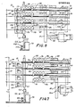
- FIG. 15 shows the schematic diagram, as a function of time, of the passage of the welding current 221, of the displacement of the mobile electrodes 154 relative to the contrast electrodes 157 and 171 and of the displacement of the units 43 or of the electrodes 171. Also shown , the movements of the clamps 127, of the operating members 122 and 123, of the wire 37 on the arms 105 as well as the movements of the arms 111.
- the following description relates to the planar assembly machine.
- the longitudinal wires 34 before their welding on the spacer wires 35, are unwound reels 240 (FIG. 1) of large capacity and are previously straightened, by means of a wire straightening machine 241.
- This machine of the type known, is not detailed here. It is generally provided with a series of rollers and counter-rolls of rectification 242 which straighten the wires.
- the wires are stiffened under the effect of the unwinding and deformations dms to. the torsion imprinted during this phase.
- the assembly machine 38 intended for trellis 36 comprises an elongated bench 245 having an entry area and an exit area 244.
- the bench 245 (FIG. 17) is provided with a series of crosspieces 246 capable of retaining the longitudinal wires 34.
- the wires longitudinal 34 are furthermore summarily held at predetermined reciprocal distances by suitable guides 247 movable along the crosspieces.
- alignment supports 246 carefully calibrated and of a length such that the longitudinal wires 34 come to be arranged substantially parallel to one another in a reference zone next to the support area to itself.
- the wires 34 lie substantially in the same plane; the reciprocal distance between the same wires is therefore very precise and has very low tolerances, compared to the project data.
- the device 250 is designed so that it can arrange each spacer wire 35 so as to cross the longitudinal wires 34, parallel to each other, so that each wire is as close as possible to or in contact with the wires 34 in their reference section.
- the device 250 (FIG. 18) comprises in particular a hopper 252 provided with an outlet channel 253 controlled by an operating member 254, a plurality of inclined bars 256 and a series of small stop wings 258.
- the welding unit 251 includes a fixed electrode 260, placed slightly below the wires 34 and transversely to the wires in their reference zone, and a group of mobile electrodes 261.
- the active part of these electrodes 261 is substantially parallel to the active part of the electrode 260, and the electrodes 261 are designed to move vertically relative to the electrode 260 under the action of the corresponding operating members 262,
- the electrodes 261, in their downward movement, are designed to cooperate with a spacer wire 35 and pushing it against the longitudinal wires 34 which, in turn, are stopped by the fixed electrode 260 in the respective crossing zones with a view to the successive welding of the wires 34 and 35.
- the machine 38 further comprises a advancement member 270 capable of advancing the longitudinal wires with respect to the electrodes 260 and 261 by a value perfectly equal to the pitch of the spacer wires.
- This device comprises transverse teeth 272 displaced by a chain 273 and capable of engaging the spacer wires 35 after their welding.
- the stroke of the teeth 272 is carefully controlled by an extension coder 275 which records exactly the angular displacements of an axis 276 on which is fixed a toothed wheel cooperating with the chain 271.
- This chain is, in turn, moved by a servo-mechanism comprising a motor 277 controlled by the extension coder in accordance with a program synchronized with the movement of the electrodes 261 and with the welding of the wires.
- a cutting device 278 actuated by a pneumatic control member 279 and comprising scissors capable of exactly cutting the spacer wire 35 adjacent to the weld zones with the longitudinal wires 34 located outside the lattice.
- the trellises themselves therefore have very precise dimensions, which allows a precise succession of the assembly operations of the structure 30 on the machine 40.
- the machine 38 makes it possible to assemble several trellises at the same time. This operation is carried out using a single transverse wire for several trellises. These are then separated during the same cutting phase following the welding.
- the different phases of advancement of the mesh, welding and cutting are controlled from a control unit 281 which comprises a microprocessor 282 (FIG. 19) and a control console 283. On the microprocessor 282 can be programmed and synchronized the different work stages, the progress stage and the welding times.
- FIG. 20 summarizes the different phases of assembly of the structure 30.
- phase 290 the welding and twisting of the wires 34, 35 and 37 are carried out, which will be cut respectively in phases 291, 292 and 293.
- the wires 34 are respectively placed on the supports 246 of the machine 38 and the wires 35 on the appropriate hopper 252.
- the wires 34 - and 35 are welded in phase 296 and then cut in phase 297.
- the trellis can be picked up in phase 299 and placed on the support planes 81 of the assembly machine 40.
- the transverse wires 37 will in turn be picked up in hoppers 101 during phase 211.
Landscapes
- Engineering & Computer Science (AREA)
- Mechanical Engineering (AREA)
- Architecture (AREA)
- Manufacturing & Machinery (AREA)
- Civil Engineering (AREA)
- Structural Engineering (AREA)
- Wire Processing (AREA)
- Butt Welding And Welding Of Specific Article (AREA)
- Catalysts (AREA)
- Crystals, And After-Treatments Of Crystals (AREA)
Priority Applications (35)
| Application Number | Priority Date | Filing Date | Title |
|---|---|---|---|
| EP84870056A EP0162183B1 (de) | 1984-04-24 | 1984-04-24 | Verfahren zum Zusammensetzen dreidimensionaler Strukturen aus Metalldraht, und Maschine zur Durchführung des Verfahrens |
| AT84870056T ATE39070T1 (de) | 1984-04-24 | 1984-04-24 | Verfahren zum zusammensetzen dreidimensionaler strukturen aus metalldraht, und maschine zur durchfuehrung des verfahrens. |
| DE8484870056T DE3475487D1 (en) | 1984-04-24 | 1984-04-24 | Method of assembling three-dimensional metal wire structures, and machine for carrying out the method |
| ZA852713A ZA852713B (en) | 1984-04-24 | 1985-04-11 | Method for assembling three-dimensional metal structures,machine for the manufacturing thereof,and structures obtained with such a method |
| IN279/MAS/85A IN164625B (de) | 1984-04-24 | 1985-04-11 | |
| IL74903A IL74903A (en) | 1984-04-24 | 1985-04-15 | Method for assembling three-dimensional metal structures,machine for the manufacturing thereof,and structures obtained with such a method |
| AU41260/85A AU586424B2 (en) | 1984-04-24 | 1985-04-15 | Method for assembling three-dimensional mental structures, machine for the manufacturing thereof, and structures obtained with such a method. |
| IE955/85A IE56375B1 (en) | 1984-04-24 | 1985-04-16 | Method for assembling three-dimensional metal structures,and machine for the manufacturing thereof |
| NZ211819A NZ211819A (en) | 1984-04-24 | 1985-04-17 | Assembling three-dimensional wire mesh structures from plane wire nettings |
| MA20634A MA20410A1 (fr) | 1984-04-24 | 1985-04-17 | Procede d'assemblage de structure metalliques tridimensionnelles, machine pour leur realisation et structures realisees selon ce procede . |
| CS852853A CS276338B6 (en) | 1984-04-24 | 1985-04-18 | Apparatus for the production of three-dimensional metallic structures |
| EG252/85A EG17553A (en) | 1984-04-24 | 1985-04-22 | Method for assembling three-dimensional metal structures for the manufacturing thereof and structures obtained with such a method |
| US06/725,655 US4667707A (en) | 1984-04-24 | 1985-04-22 | Method for assembling three-dimensional metal structures, machine for the manufacturing thereof, and structures obtained with such a method |
| DK179385A DK167310B1 (da) | 1984-04-24 | 1985-04-22 | Fremgangsmaade ved og anlaeg til fremstilling af tredimensionale metalliske strukturer |
| BR8501975A BR8501975A (pt) | 1984-04-24 | 1985-04-23 | Processo de montagem de estruturas metalicas tridimensionais,maquina para sua realizacao e estruturas obtidas de acordo com o processo |
| DZ850086A DZ774A1 (fr) | 1984-04-24 | 1985-04-23 | Procédé d'assemblage de structures métalliques tridimensionnelles, machine pour leur réalisation et structures réalisée seon ce procédé. |
| DD85275469A DD243652A5 (de) | 1984-04-24 | 1985-04-23 | Verfahren zur verbindung metallischer, dreidemensionaler strukturen. maschine zu dessen durchfuehrung und nach diesem verfahren hergestellte strukturen |
| NO851613A NO179402C (no) | 1984-04-24 | 1985-04-23 | Fremgangsmåte ved og anlegg til fremstilling av tredimensjonale, metalliske konstruksjoner |
| CA000479880A CA1291323C (en) | 1984-04-24 | 1985-04-23 | Method for assembling three dimensional metal structures, machine for the manufacturing thereof, and structures obtained with such a method |
| ES542473A ES8700095A1 (es) | 1984-04-24 | 1985-04-23 | Procedimiento de ensamblado de estructuras metalicas tridi- mensionales |
| GR850987A GR850987B (de) | 1984-04-24 | 1985-04-23 | |
| AR85300164A AR242521A1 (es) | 1984-04-24 | 1985-04-23 | Maquina para ensamblar estructuras metalica y tridimensionales. |
| PT80331A PT80331B (pt) | 1984-04-24 | 1985-04-23 | Processo de montagem de estruturas metalicas tridimensionais maquina para a sua realizacao e estruturas realizadas por este processo |
| FI851607A FI84328C (fi) | 1984-04-24 | 1985-04-23 | Foerfarande och maskin foer hopsaettning av tredimensionella metallkonstruktioner. |
| SU853913952A RU2012433C1 (ru) | 1984-04-24 | 1985-04-23 | Способ сборки пространственных металлических конструкций, машина для его осуществления |
| KR1019850002772A KR900000317B1 (ko) | 1984-04-24 | 1985-04-24 | 조립식 건축부재용 입체철망구조물 제작방법과 그 장치 |
| YU69185A YU47398B (sh) | 1984-04-24 | 1985-04-24 | Mašina za montiranje trodimenzionalnih metalnih konstrukcija |
| SI8510691A SI8510691B (sl) | 1984-04-24 | 1985-04-24 | Postopek montiranja trodimenzionalnih kovinskih konstrukcij, naprava za njihovo izdelavo in konstrukcije dobljene po takšnem postopku |
| TR22097A TR22097A (tr) | 1984-04-24 | 1985-04-24 | Uec boyutlu metalik struektuerlerin montaj usulue,bunlarin yapilmasi icin makine ve bu usule goere yapilan struektuerler |
| PL25307385A PL253073A1 (en) | 1984-04-24 | 1985-04-24 | Method of jointing members of there-dimensional metal structure,method of assembling two-dimensional latticeworks into three-dimensional structure and apparatus therefor |
| JP8661585A JPS6133727A (ja) | 1984-04-24 | 1985-04-24 | 三次元金属構造体の製造方法及び装置 |
| PH32182A PH22925A (en) | 1984-04-24 | 1985-04-24 | Method for assembling three-dimensional metal structures machine for the manufacturing thereof, and structures obtained with such a method |
| US07/022,865 US4838322A (en) | 1984-04-24 | 1987-03-06 | Method for assembling three-dimensional metal structures, machine for the manufacturing thereof, and structures obtained with such a method |
| MYPI87001592A MY101363A (en) | 1984-04-24 | 1987-09-08 | Method for assembling three-dimensional metal structures, machine for the manufacturing thereof, and structures obtained with such a method. |
| HR920447A HRP920447A2 (en) | 1984-04-24 | 1992-09-24 | Method of assembling three-dimensional metal wire structures, machine for carrying out the method and structures made by this method |
Applications Claiming Priority (1)
| Application Number | Priority Date | Filing Date | Title |
|---|---|---|---|
| EP84870056A EP0162183B1 (de) | 1984-04-24 | 1984-04-24 | Verfahren zum Zusammensetzen dreidimensionaler Strukturen aus Metalldraht, und Maschine zur Durchführung des Verfahrens |
Publications (2)
| Publication Number | Publication Date |
|---|---|
| EP0162183A1 true EP0162183A1 (de) | 1985-11-27 |
| EP0162183B1 EP0162183B1 (de) | 1988-12-07 |
Family
ID=8193138
Family Applications (1)
| Application Number | Title | Priority Date | Filing Date |
|---|---|---|---|
| EP84870056A Expired EP0162183B1 (de) | 1984-04-24 | 1984-04-24 | Verfahren zum Zusammensetzen dreidimensionaler Strukturen aus Metalldraht, und Maschine zur Durchführung des Verfahrens |
Country Status (32)
| Country | Link |
|---|---|
| US (1) | US4667707A (de) |
| EP (1) | EP0162183B1 (de) |
| JP (1) | JPS6133727A (de) |
| KR (1) | KR900000317B1 (de) |
| AR (1) | AR242521A1 (de) |
| AT (1) | ATE39070T1 (de) |
| AU (1) | AU586424B2 (de) |
| BR (1) | BR8501975A (de) |
| CA (1) | CA1291323C (de) |
| CS (1) | CS276338B6 (de) |
| DD (1) | DD243652A5 (de) |
| DE (1) | DE3475487D1 (de) |
| DK (1) | DK167310B1 (de) |
| DZ (1) | DZ774A1 (de) |
| EG (1) | EG17553A (de) |
| ES (1) | ES8700095A1 (de) |
| FI (1) | FI84328C (de) |
| GR (1) | GR850987B (de) |
| IE (1) | IE56375B1 (de) |
| IL (1) | IL74903A (de) |
| IN (1) | IN164625B (de) |
| MA (1) | MA20410A1 (de) |
| MY (1) | MY101363A (de) |
| NO (1) | NO179402C (de) |
| NZ (1) | NZ211819A (de) |
| PH (1) | PH22925A (de) |
| PL (1) | PL253073A1 (de) |
| PT (1) | PT80331B (de) |
| RU (1) | RU2012433C1 (de) |
| TR (1) | TR22097A (de) |
| YU (1) | YU47398B (de) |
| ZA (1) | ZA852713B (de) |
Cited By (5)
| Publication number | Priority date | Publication date | Assignee | Title |
|---|---|---|---|---|
| GB2196660A (en) * | 1986-10-29 | 1988-05-05 | Shimizu Construction Co Ltd | Wire mesh truss for wall panels |
| EP1447488A1 (de) | 2003-02-11 | 2004-08-18 | Kildare Developments Ltd. | Vorgefertigte Module zur Verwendung in der Bauindustrie |
| WO2010095076A1 (en) | 2009-02-20 | 2010-08-26 | Schnell S.P.A. | Method and apparatus for making reinforcements for reinforced concrete |
| ITBO20100758A1 (it) * | 2010-12-23 | 2012-06-24 | Schnell Spa | Metodo e apparecchiatura per realizzare armature per cemento armato |
| RU2485420C2 (ru) * | 2008-02-22 | 2013-06-20 | Бсх Бош Унд Сименс Хаусгерете Гмбх | Холодильный аппарат без намерзания инея |
Families Citing this family (6)
| Publication number | Priority date | Publication date | Assignee | Title |
|---|---|---|---|---|
| IT1213688B (it) * | 1987-09-22 | 1989-12-29 | Monolite Srl | Apparecchiatura per realizzare pannelli per la costruzione di pareti con caratteristiche antisismiche edi isolamento termoacustico |
| US4911209A (en) * | 1989-03-15 | 1990-03-27 | Expo Wire Company | Method and apparatus for forming wire mesh cages |
| KR920005633Y1 (ko) * | 1990-09-20 | 1992-08-18 | 안세흥 | 건축용 패널(Panel)의 제조장치 |
| AU2002219195A1 (en) * | 2001-12-13 | 2003-06-23 | Kildare Developments Ltd. | Method for assembling three-dimensional structures device for implementing said method and structures obtained by said method |
| IT1391697B1 (it) * | 2008-11-07 | 2012-01-17 | Beta Systems S R L Ora Beta Systems S R L A Socio Unico | Macchina per la formazione di rete metallica e relativo gruppo di saldatura |
| IT201700007565A1 (it) * | 2017-01-24 | 2018-07-24 | M E P Macch Elettroniche Piegatrici Spa | Apparato e metodo per realizzare una rete metallica |
Citations (3)
| Publication number | Priority date | Publication date | Assignee | Title |
|---|---|---|---|---|
| DE1584692B1 (de) * | 1963-03-06 | 1971-08-05 | Sp K Bjuro Prokatdetal | Vorrichtung zur kontinuierlichen Herstellung einer Bewehrung fuer Stahlbetonbauteile |
| DE2212291A1 (de) * | 1971-03-16 | 1972-10-26 | Asahi Chemical Ind | Verfahren und Vorrichtung zur Herstellung von Kaefigen aus Bewehrungsstangen |
| FR2177030A1 (de) * | 1972-03-22 | 1973-11-02 | Weismann V |
Family Cites Families (12)
| Publication number | Priority date | Publication date | Assignee | Title |
|---|---|---|---|---|
| US1783948A (en) * | 1929-11-04 | 1930-12-02 | William H Sommer | Method of making wire fabrics |
| US2390174A (en) * | 1943-01-01 | 1945-12-04 | George R Roemer | Continuous manufacture of welded wire mesh |
| JPS5319984B2 (de) * | 1972-03-22 | 1978-06-23 | ||
| BE885563Q (fr) * | 1976-01-05 | 1981-02-02 | Cs & M Inc | Treillis de fils metallique et appareil pour sa fabrication |
| JPS5333940A (en) * | 1976-09-10 | 1978-03-30 | Mitsubishi Heavy Ind Ltd | Means for fabricating three dimentional truss |
| JPS5347343A (en) * | 1976-10-13 | 1978-04-27 | Mitsubishi Heavy Ind Ltd | Process for fabricating threeedimentioned metal mesh |
| JPS5371654A (en) * | 1976-12-08 | 1978-06-26 | Mitsubishi Heavy Ind Ltd | Production device of solid welded gauze |
| US4340802A (en) * | 1977-12-05 | 1982-07-20 | Covington Brothers Technologies | Method and apparatus for welding |
| JPS5949163B2 (ja) * | 1979-10-01 | 1984-12-01 | 東レエンジニアリング株式会社 | コンクリ−ト板用補強鉄筋配列組立装置 |
| IT1191160B (it) * | 1981-03-18 | 1988-02-24 | Silvano Casalatina | Dispositivo e metodo per ottenere elementi prefabbricati per la costruzione di case e simili e metodo per assemblare tra loro detti elementi |
| AT373799B (de) * | 1981-07-28 | 1984-02-27 | Evg Entwicklung Verwert Ges | Vielpunktschweissmaschine zum herstellen von gittern oder gitterrosten |
| GR76427B (de) * | 1981-07-28 | 1984-08-10 | Beaumond Jean J |
-
1984
- 1984-04-24 EP EP84870056A patent/EP0162183B1/de not_active Expired
- 1984-04-24 AT AT84870056T patent/ATE39070T1/de not_active IP Right Cessation
- 1984-04-24 DE DE8484870056T patent/DE3475487D1/de not_active Expired
-
1985
- 1985-04-11 IN IN279/MAS/85A patent/IN164625B/en unknown
- 1985-04-11 ZA ZA852713A patent/ZA852713B/xx unknown
- 1985-04-15 AU AU41260/85A patent/AU586424B2/en not_active Ceased
- 1985-04-15 IL IL74903A patent/IL74903A/xx not_active IP Right Cessation
- 1985-04-16 IE IE955/85A patent/IE56375B1/en not_active IP Right Cessation
- 1985-04-17 NZ NZ211819A patent/NZ211819A/en unknown
- 1985-04-17 MA MA20634A patent/MA20410A1/fr unknown
- 1985-04-18 CS CS852853A patent/CS276338B6/cs not_active IP Right Cessation
- 1985-04-22 US US06/725,655 patent/US4667707A/en not_active Expired - Lifetime
- 1985-04-22 DK DK179385A patent/DK167310B1/da not_active IP Right Cessation
- 1985-04-22 EG EG252/85A patent/EG17553A/xx active
- 1985-04-23 PT PT80331A patent/PT80331B/pt not_active IP Right Cessation
- 1985-04-23 FI FI851607A patent/FI84328C/fi not_active IP Right Cessation
- 1985-04-23 AR AR85300164A patent/AR242521A1/es active
- 1985-04-23 ES ES542473A patent/ES8700095A1/es not_active Expired
- 1985-04-23 NO NO851613A patent/NO179402C/no not_active IP Right Cessation
- 1985-04-23 CA CA000479880A patent/CA1291323C/en not_active Expired - Lifetime
- 1985-04-23 RU SU853913952A patent/RU2012433C1/ru active
- 1985-04-23 DD DD85275469A patent/DD243652A5/de not_active IP Right Cessation
- 1985-04-23 BR BR8501975A patent/BR8501975A/pt not_active IP Right Cessation
- 1985-04-23 DZ DZ850086A patent/DZ774A1/fr active
- 1985-04-23 GR GR850987A patent/GR850987B/el not_active IP Right Cessation
- 1985-04-24 TR TR22097A patent/TR22097A/xx unknown
- 1985-04-24 JP JP8661585A patent/JPS6133727A/ja active Granted
- 1985-04-24 YU YU69185A patent/YU47398B/sh unknown
- 1985-04-24 PH PH32182A patent/PH22925A/en unknown
- 1985-04-24 KR KR1019850002772A patent/KR900000317B1/ko not_active IP Right Cessation
- 1985-04-24 PL PL25307385A patent/PL253073A1/xx unknown
-
1987
- 1987-09-08 MY MYPI87001592A patent/MY101363A/en unknown
Patent Citations (3)
| Publication number | Priority date | Publication date | Assignee | Title |
|---|---|---|---|---|
| DE1584692B1 (de) * | 1963-03-06 | 1971-08-05 | Sp K Bjuro Prokatdetal | Vorrichtung zur kontinuierlichen Herstellung einer Bewehrung fuer Stahlbetonbauteile |
| DE2212291A1 (de) * | 1971-03-16 | 1972-10-26 | Asahi Chemical Ind | Verfahren und Vorrichtung zur Herstellung von Kaefigen aus Bewehrungsstangen |
| FR2177030A1 (de) * | 1972-03-22 | 1973-11-02 | Weismann V |
Cited By (7)
| Publication number | Priority date | Publication date | Assignee | Title |
|---|---|---|---|---|
| GB2196660A (en) * | 1986-10-29 | 1988-05-05 | Shimizu Construction Co Ltd | Wire mesh truss for wall panels |
| GB2196660B (en) * | 1986-10-29 | 1991-06-26 | Shimizu Construction Co Ltd | Wire mesh truss used as building wall element |
| EP1447488A1 (de) | 2003-02-11 | 2004-08-18 | Kildare Developments Ltd. | Vorgefertigte Module zur Verwendung in der Bauindustrie |
| RU2485420C2 (ru) * | 2008-02-22 | 2013-06-20 | Бсх Бош Унд Сименс Хаусгерете Гмбх | Холодильный аппарат без намерзания инея |
| WO2010095076A1 (en) | 2009-02-20 | 2010-08-26 | Schnell S.P.A. | Method and apparatus for making reinforcements for reinforced concrete |
| EP2398607B1 (de) * | 2009-02-20 | 2019-06-05 | Schnell S.p.A. | Verfahren und vorrichtung zur herstellung von armierungen für armierten beton |
| ITBO20100758A1 (it) * | 2010-12-23 | 2012-06-24 | Schnell Spa | Metodo e apparecchiatura per realizzare armature per cemento armato |
Also Published As
Similar Documents
| Publication | Publication Date | Title |
|---|---|---|
| EP0162183A1 (de) | Verfahren zum Zusammensetzen dreidimensionaler Strukturen aus Metalldraht, und Maschine zur Durchführung des Verfahrens | |
| DE2129642A1 (de) | Vorrichtung zum UEberfuehren von elektrischen Leitungsdraehten | |
| FR2494542A1 (fr) | Procede et appareil pour la fabrication de faisceaux de fils de cablage | |
| FR2553692A1 (fr) | Procede et dispositif de fabrication de caillebotis | |
| FR2575944A1 (fr) | Procede et dispositif pour le cintrage automatique de tubes metalliques | |
| EP0445044B1 (de) | Rohrbiegevorrichtung mit zwei Biegeköpfen | |
| US4838322A (en) | Method for assembling three-dimensional metal structures, machine for the manufacturing thereof, and structures obtained with such a method | |
| EP0435769A1 (de) | Verfahren und automatische Vorrichtung zur Herstellung einer Stahlbewehrung und mit diesem Verfahren hergestellte Stahlbewehrung | |
| CH411006A (fr) | Procédé pour souder des fils sur les serpentins de condenseurs, et machine pour sa mise en oeuvre | |
| FR2772652A1 (fr) | Procede et dispositif de formage de fils metalliques | |
| CH625724A5 (de) | ||
| FR2597290A1 (fr) | Procede et appareil de fabrication de faisceaux de conducteurs | |
| US3936628A (en) | Apparatus for forming elongate reinforcing elements | |
| EP0020222A1 (de) | Automatische Maschine zum Zusammensetzen von Lamellen, insbesondere für Wärmeaustauscher oder Heizkörper | |
| FR2613962A1 (fr) | Procede et automate de pliage automatique de toles | |
| EP0163568B1 (de) | Gerät zum Einsetzen von haarnadelförmigen Federn auf Platten, insbesondere für Roste einer Brennstoffanordnung | |
| FR2634676A1 (fr) | Dispositif pour plier des materiaux de forme allongee tels que fils metalliques, materiaux en bande ou profiles | |
| FR2526699A1 (fr) | Appareil et procede pour realiser la commande programmee de fonctions de travail, notamment pour le soudage d'elements de batterie | |
| EP1162013B1 (de) | Werkstücktransfervorrichtung für eine Stanz- und/oder eine Schneidpresse | |
| EP1270110A2 (de) | Verfahren und Vorrichtung zur Herstellung von Metallrahmen für Stahlbeton und damit hergestellte Metallrahmen | |
| FR2716818A1 (fr) | Machine automatique à fabriquer les clisses. | |
| BE659550A (de) | ||
| FR2657547A1 (fr) | Dispositif pour la fabrication de pieces metalliques en forme d'etrier comportant une double courbure. | |
| FR2563129A1 (fr) | Procede et dispositif pour le formage de pieces par estampage | |
| FR2650209A1 (fr) | Cellule de presse a sertir |
Legal Events
| Date | Code | Title | Description |
|---|---|---|---|
| PUAI | Public reference made under article 153(3) epc to a published international application that has entered the european phase |
Free format text: ORIGINAL CODE: 0009012 |
|
| AK | Designated contracting states |
Designated state(s): AT BE CH DE FR GB IT LI LU NL SE |
|
| 17P | Request for examination filed |
Effective date: 19860523 |
|
| 17Q | First examination report despatched |
Effective date: 19870928 |
|
| GRAA | (expected) grant |
Free format text: ORIGINAL CODE: 0009210 |
|
| AK | Designated contracting states |
Kind code of ref document: B1 Designated state(s): AT BE CH DE FR GB IT LI LU NL SE |
|
| REF | Corresponds to: |
Ref document number: 39070 Country of ref document: AT Date of ref document: 19881215 Kind code of ref document: T |
|
| ITF | It: translation for a ep patent filed | ||
| REF | Corresponds to: |
Ref document number: 3475487 Country of ref document: DE Date of ref document: 19890112 |
|
| GBT | Gb: translation of ep patent filed (gb section 77(6)(a)/1977) | ||
| PLBE | No opposition filed within time limit |
Free format text: ORIGINAL CODE: 0009261 |
|
| STAA | Information on the status of an ep patent application or granted ep patent |
Free format text: STATUS: NO OPPOSITION FILED WITHIN TIME LIMIT |
|
| 26N | No opposition filed | ||
| ITTA | It: last paid annual fee | ||
| EPTA | Lu: last paid annual fee | ||
| EAL | Se: european patent in force in sweden |
Ref document number: 84870056.3 |
|
| PGFP | Annual fee paid to national office [announced via postgrant information from national office to epo] |
Ref country code: GB Payment date: 19981016 Year of fee payment: 15 |
|
| PG25 | Lapsed in a contracting state [announced via postgrant information from national office to epo] |
Ref country code: GB Free format text: LAPSE BECAUSE OF NON-PAYMENT OF DUE FEES Effective date: 19990424 |
|
| GBPC | Gb: european patent ceased through non-payment of renewal fee |
Effective date: 19990424 |
|
| PGFP | Annual fee paid to national office [announced via postgrant information from national office to epo] |
Ref country code: LU Payment date: 20020304 Year of fee payment: 19 |
|
| PGFP | Annual fee paid to national office [announced via postgrant information from national office to epo] |
Ref country code: AT Payment date: 20020320 Year of fee payment: 19 |
|
| PGFP | Annual fee paid to national office [announced via postgrant information from national office to epo] |
Ref country code: SE Payment date: 20020405 Year of fee payment: 19 |
|
| PGFP | Annual fee paid to national office [announced via postgrant information from national office to epo] |
Ref country code: CH Payment date: 20020415 Year of fee payment: 19 |
|
| PGFP | Annual fee paid to national office [announced via postgrant information from national office to epo] |
Ref country code: NL Payment date: 20020426 Year of fee payment: 19 |
|
| PGFP | Annual fee paid to national office [announced via postgrant information from national office to epo] |
Ref country code: DE Payment date: 20020502 Year of fee payment: 19 |
|
| PGFP | Annual fee paid to national office [announced via postgrant information from national office to epo] |
Ref country code: BE Payment date: 20030305 Year of fee payment: 20 |
|
| PG25 | Lapsed in a contracting state [announced via postgrant information from national office to epo] |
Ref country code: LU Free format text: LAPSE BECAUSE OF NON-PAYMENT OF DUE FEES Effective date: 20030424 Ref country code: AT Free format text: LAPSE BECAUSE OF NON-PAYMENT OF DUE FEES Effective date: 20030424 |
|
| PGFP | Annual fee paid to national office [announced via postgrant information from national office to epo] |
Ref country code: FR Payment date: 20030424 Year of fee payment: 20 |
|
| PG25 | Lapsed in a contracting state [announced via postgrant information from national office to epo] |
Ref country code: SE Free format text: LAPSE BECAUSE OF NON-PAYMENT OF DUE FEES Effective date: 20030425 |
|
| PG25 | Lapsed in a contracting state [announced via postgrant information from national office to epo] |
Ref country code: LI Free format text: LAPSE BECAUSE OF NON-PAYMENT OF DUE FEES Effective date: 20030430 Ref country code: CH Free format text: LAPSE BECAUSE OF NON-PAYMENT OF DUE FEES Effective date: 20030430 |
|
| PG25 | Lapsed in a contracting state [announced via postgrant information from national office to epo] |
Ref country code: NL Free format text: LAPSE BECAUSE OF NON-PAYMENT OF DUE FEES Effective date: 20031101 Ref country code: DE Free format text: LAPSE BECAUSE OF NON-PAYMENT OF DUE FEES Effective date: 20031101 |
|
| NLV4 | Nl: lapsed or anulled due to non-payment of the annual fee |
Effective date: 20031101 |
|
| EUG | Se: european patent has lapsed | ||
| REG | Reference to a national code |
Ref country code: CH Ref legal event code: PL |
|
| BE20 | Be: patent expired |
Owner name: *SISMO INTERNATIONAL P.V.B.A. Effective date: 20040424 |