EP0162183A1 - Method of assembling three-dimensional metal wire structures, and machine for carrying out the method - Google Patents
Method of assembling three-dimensional metal wire structures, and machine for carrying out the method Download PDFInfo
- Publication number
- EP0162183A1 EP0162183A1 EP84870056A EP84870056A EP0162183A1 EP 0162183 A1 EP0162183 A1 EP 0162183A1 EP 84870056 A EP84870056 A EP 84870056A EP 84870056 A EP84870056 A EP 84870056A EP 0162183 A1 EP0162183 A1 EP 0162183A1
- Authority
- EP
- European Patent Office
- Prior art keywords
- wires
- spacer
- longitudinal
- welding
- trellis
- Prior art date
- Legal status (The legal status is an assumption and is not a legal conclusion. Google has not performed a legal analysis and makes no representation as to the accuracy of the status listed.)
- Granted
Links
Images


Classifications
-
- E—FIXED CONSTRUCTIONS
- E04—BUILDING
- E04C—STRUCTURAL ELEMENTS; BUILDING MATERIALS
- E04C5/00—Reinforcing elements, e.g. for concrete; Auxiliary elements therefor
- E04C5/01—Reinforcing elements of metal, e.g. with non-structural coatings
- E04C5/06—Reinforcing elements of metal, e.g. with non-structural coatings of high bending resistance, i.e. of essentially three-dimensional extent, e.g. lattice girders
-
- B—PERFORMING OPERATIONS; TRANSPORTING
- B21—MECHANICAL METAL-WORKING WITHOUT ESSENTIALLY REMOVING MATERIAL; PUNCHING METAL
- B21F—WORKING OR PROCESSING OF METAL WIRE
- B21F27/00—Making wire network, i.e. wire nets
- B21F27/08—Making wire network, i.e. wire nets with additional connecting elements or material at crossings
- B21F27/10—Making wire network, i.e. wire nets with additional connecting elements or material at crossings with soldered or welded crossings
-
- B—PERFORMING OPERATIONS; TRANSPORTING
- B21—MECHANICAL METAL-WORKING WITHOUT ESSENTIALLY REMOVING MATERIAL; PUNCHING METAL
- B21F—WORKING OR PROCESSING OF METAL WIRE
- B21F27/00—Making wire network, i.e. wire nets
- B21F27/12—Making special types or portions of network by methods or means specially adapted therefor
- B21F27/121—Making special types or portions of network by methods or means specially adapted therefor of tubular form, e.g. as reinforcements for pipes or pillars
-
- B—PERFORMING OPERATIONS; TRANSPORTING
- B21—MECHANICAL METAL-WORKING WITHOUT ESSENTIALLY REMOVING MATERIAL; PUNCHING METAL
- B21F—WORKING OR PROCESSING OF METAL WIRE
- B21F27/00—Making wire network, i.e. wire nets
- B21F27/12—Making special types or portions of network by methods or means specially adapted therefor
- B21F27/128—Making special types or portions of network by methods or means specially adapted therefor of three-dimensional form by connecting wire networks, e.g. by projecting wires through an insulating layer
-
- B—PERFORMING OPERATIONS; TRANSPORTING
- B23—MACHINE TOOLS; METAL-WORKING NOT OTHERWISE PROVIDED FOR
- B23K—SOLDERING OR UNSOLDERING; WELDING; CLADDING OR PLATING BY SOLDERING OR WELDING; CUTTING BY APPLYING HEAT LOCALLY, e.g. FLAME CUTTING; WORKING BY LASER BEAM
- B23K11/00—Resistance welding; Severing by resistance heating
- B23K11/002—Resistance welding; Severing by resistance heating specially adapted for particular articles or work
- B23K11/008—Manufacturing of metallic grids or mats by spot welding
Definitions
- the invention relates to a method of assembling three-dimensional metal structures, by way of example for prefabricated elements such as panels or ceilings to be used in construction.
- the invention also relates to the machines which carry out this process and, finally, to the structure produced according to this same process.
- a three-dimensional structure of metal wires comprising a series of planar trellises. Each trellis is provided with at least one pair of longitudinal wires and spacer wires. The trellises have predetermined reciprocal distances thanks to a series of transverse wires welded to the trellises themselves and to strut wires.
- Such a structure forms support planes for elongated bodies of corresponding dimensions made of inserted light and insulating material. inside the structure itself.
- the production of these structures requires very little tolerance of the different components and meticulous alignment between these parts during the welding phases. To meet these requirements, numerous manual interventions to carry the welding units to the crossing zones of the solder wire and to maintain alignment between the parts are required. Such a process is therefore necessarily expensive.
- the three-dimensional structure produced according to the method according to the invention is characterized by a remarkable resistance to stresses, thanks to the twist of the wires and to the precision of the welds.
- This structure is further characterized by an accuracy in the planes of the different spacer wires, in order to obtain very reduced spaces between the elongated bodies inserted inside the structure itself.
- the assembled structure has great dimensional precision in order to guarantee an optimal arrangement of the panels during construction.
- the assembly method according to the invention is intended to produce, for example but not exclusively, three-dimensional metallic structures 30 (FIG. 2) of the kind described in European patent application No. 82102021 published on September 29, 82.
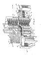
- the aim of this process is, in particular, to assemble plane trellises 36 made of steel wires with transverse wires 37 and preferably provides for the use of a machine allowing the three-dimensional structure 40 to be assembled.
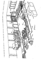
- the lattice 36 comprises son longitudinal strut 34 and 35 and son are at an earlier stage than that of assembling the three-dimensional structure achieved s by means of a plate welder 38 (figure 1).
- the assembly machine 40 (FIG. 2) comprises a support structure 41 which supports the mesh 36, a feed group 42 from which the transverse wires 37 are taken to be welded to the mesh 36, a series of welding units 43 and a feed group 45 for the structure 30, during the assembly, and a collection assembly 50 (FIG. 1).
- the machine also provides an electronic group 57 (FIG. 10) for the sequential control of the various assembly and welding phases, a control console 58, a pneumatic unit 59 for carrying out the commands or orders sent by the unit 58 and a hydraulic unit 60 for cooling the welding electrodes of the assembly machines 38 and 40.
- an electronic group 57 (FIG. 10) for the sequential control of the various assembly and welding phases
- a control console 58 for the sequential control of the various assembly and welding phases
- a pneumatic unit 59 for carrying out the commands or orders sent by the unit 58
- a hydraulic unit 60 for cooling the welding electrodes of the assembly machines 38 and 40.
- the following description relates to the support structure.
- the support structure 41 comprises a group of uprights 79 on which are fixed at predetermined distances, in pairs, a series of crosspieces 80.
- the crosspieces 80 in turn support a series of horizontal and superimposed support planes 81.
- the distances between the planes 81 are equal to each other and regulate the transverse pitch of the planar lattice 36 relative to the structure 30 already assembled.
- the planes 81 are of very elongated rectangular shape and are provided with two lateral sides 82 and 83, respectively left and right, if one refers to FIG. 4, and support a trellis corresponding to plane 36.
- a control element 83 formed of a a drawing of rectangular section, is fixed to each side 82 and is provided with a control surface 85 capable of collaborating with the ends, on the left in the figure, of the spacer wires 35 of the trellises 36.
- the surfaces 85 of the control elements 83 of the different planes 81 are located in the same planet define a vertical reference surface of the three-dimensional structure 30.
- Another control element 86 also consisting of a drawing of rectangular section, is fixed, in an adjustable manner to the side 83 of each plane 81 and is provided with a surface 87 with which the ends can collaborate, on the right in the figure. , spacer wires 35 of the trellises 36.
- the surfaces 87 of the control elements 86 are located in the same plane and define another vertical reference plane of the three-dimensional structure 30, parallel to the vertical plane defined by the surfaces 85.
- two reference planes are such that they bring the longitudinal wires 34 in the same plane, on the same side of the different trellises 36 and are, moreover, perpendicular to the planes of the same trellises 36.
- control elements 85 and 86 are fixed guide elements 92 and 93 formed of U- shaped wire sections projecting out of the planes 81. These elements collaborate with the ends of the spacer wires 3 5 as well as q u 'with the longitudinal wires 34 of the planar lattices 36 and serve to define with precision the vertical reference planes of the structure 30 and to avoid warping of the lattices 36 in the area close to the outlet end of the guide elements 92 and 93, adjacent to the welding units 43.
- control elements 87 and the guide elements 93 can be moved relative to the sides 83, for example using screws 94.
- the distance between the reference planes of the surfaces 87 and the guide elements 92 can be modified either with respect to the reference plane of the surfaces 85, or with respect to the guide elements 93, to define exactly the vertical reference planes of the structures 30 using lattices 36 of different widths.
- a feeding group follows on from the support structure.
- This supply group 42 is divided into two units, each of which comprises a hopper 101 (FIG. 2) in which are arranged such as transverse wires 37.
- the wires penetrate by gravity into an outlet channel 102 (FIG. 11) and this operation is facilitated by the action of an eccentric 103.
- a device 104 is arranged for dropping one by one the wires 37 which, after having been guided by the inclined bars 105, stop at the base of the bars 105, abutting against shoulders 106.
- the presence of the wire 37, retained against the shoulders 106 is detected by a magnetic signaler 107 which transmits, in the form of electrical signals, the information in question to the control unit 57.
- each gripping arm III is formed by a parallelepiped bar with a fulcrum at one end and an output shaft 112 of a pneumatic actuator 113.
- This actuator l13 is provided to rotate the gripping arm from a horizontal position to a vertical position.
- Each gripping arm 111 is, in its horizontal position, substantially aligned and superimposed on the wire 37 temporarily stopped against the shoulders 106 and near the wire itself.
- a number of magnets 114 are arranged to separate the wire 37 from the shoulders 106 and to hold it on the arm 111 in alignment with the axis of the same arm.
- Two sensors 115 and 116 also have the task of detecting the horizontal position and the vertical position of the arm 111 respectively and of transmitting the information to the control unit 57.
- two pneumatic operating members 121 Facing the hopper 101 (FIGS. 2 and 3), are arranged two pneumatic operating members 121, provided with pistons 122, movable in a horizontal plane in a direction perpendicular to the reference planes of the surfaces 85 and 86.
- pistons 122 On the pistons 122 are fixed two corresponding support blocks 123 on which are fixed in turn two other pneumatic actuators 124.
- actuators 124 are provided with pistons 125 which are movable horizontally in a direction inclined by 45 ° relative to the reference planes of the surfaces 85 and 86.
- the pistons 125 support two uprights 126 to which are fixed two corresponding series of pliers 127, pneumatically operated, capable of separating the wires 37 from the arms 111 and of holding them parallel to the uprights 126.
- Sensors 128 make it possible to detect the presence of one or more wires 37 retained by the clamps 127.
- the supports 123 can be moved away from the pistons 122 from lateral positions near the hoppers towards central positions close to the welding units 43 and the elements guide 92 and 93.
- the uprights 126 can, in turn, be moved away from the pistons 125 from positions remote from the hoppers 101 and from the guide elements 92 and 93 towards zones close to the arms 111, arranged in a vertical position, and welding units 43.
- End-of-travel sensors 131 and 132 of the operating members 121 respectively detect the lateral and central positions of the blocks 123 and end-of-travel sensors 133 of the operating members 124 detect the positions of the uprights 126 near the arms 111 and the soldering units 43.
- magnetic sensors 134 detect the presence of the wires 37 on the uprights 126, while they are held by clips 127. The information from the sensors 134 is also transmitted to the control unit 57.
- the hoppers 101 are arranged to each accept, with appropriate separating elements, two series of transverse wires 37, of a length barely less than the maximum width of the hopper itself.
- the inclined bars 105, the grip arms 111, the uprights 126, the clamps 127 and the various sensors are capable of processing both two wires 37 aligned with one another and close to each other. This allows two three-dimensional structures to be assembled at the same time with a height slightly less than half of a maximum height structure.
- the welding units 43 (FIG. 3) are divided into two groups mounted respectively on two plates 145 and 146. These plates are slidably mounted on vertical uprights 147 arranged to the left and to the right of the guide elements 92 and 93 so that a pair of welding units 43 is associated with each pair of elements 92 and 93.
- Each unit 43 comprises a body 151 in the form of a hollow parallelepiped, on which are mounted a transformer 152, a pneumatic operating member 153, a mobile electrode 154 and a contrast electrode 155.
- the movable electrode 154 is fixed to a piston 157 of the operating member 153 which, in turn, is guided by sockets insulating it from the body 151.
- the contrast electrode 155 has an L-shaped body and is electrically connected to the body 151.
- the transformer 152 is partially inserted into the parallelepiped body 151 and is provided with a primary whose terminals can be connected to the network.
- the secondary of the transformer is provided with two terminals 159 and 160 connected to the electrodes 154 and 155.
- the terminal 159 is directly connected to the electrode 155, while the connection between the electrode 154 and the terminal 160 is provided by a series of thin sheets of copper, folded U-shaped, which allow the movements of the piston 157 relative to the transformation t e ur 152.
- each mobile electrode 1 54 (FIG 5) indicated by 163, is cylindrical in shape and is arranged higher in relation to the piston 157, it is connected to the latter by a block 164.
- the active part of each electrode 155 ( indicated by 165, has the shape of a parallelepiped and protrudes upwards the electrode 155.
- the blocks 1 6 4 of the electrodes 154 and 155 are internally traversed by cooling pipes, provided with small inlet and outlet mouths 166 and 167 connected to the hydraulic unit 60.
- each plate 145, 146 is movable vertically relative to the uprights 147.
- An operating member 170 moves the welding units upwards. 43 to bring the parts 163 and 165 into alignment with the planes of the trellis 35.
- two end of travel sensors 168 and 169 can detect, respectively, the high and low positions of the units 43.
- the welding units 43 are mounted on two fixed plates 180.
- Each contrast electrode, designated by 171 is provided with a lever arm 173 and pivots around a socket 172 parallel to the piston 157.
- the active parts 163 of the movable electrodes 154 are brought into alignment with the planes of the various trellises 36, while the active parts of the electrodes 171 are arranged below these planes.
- the arms 173 pivot on a single vertical link 174 which is, in turn, connected to a pneumatic actuator 175.
- the actuator 175 is designed to pivot the electrodes 171 around the sockets 172 so as to bring the active parts 164 in alignment with the planes of the trellis 36.
- the sensors 168 and 169 detect, in this case, the respectively high positions and low of the electrodes 171.
- the group 45 comprises a pneumatic operating member 182 provided with two pistons 183 which can be moved parallel to the guide elements 92 and 93.
- a vertical bar 184 is mounted on the pistons to which are fixed horizontal arms 185 L-shaped and arranged in the space between the planes of the trellis 36.
- the arms 185 have a longitudinal part 186 arranged in the mid-plane between the vertical reference planes defined by the elements of guidance 92 and 93.
- each part 186 pivots, by means of a pivot 187, a toothed lever 190, provided below with an anterior tooth 191 and a posterior tooth 192.
- the lever 190 In the rest position, the lever 190 is held in the horizontal position by gravity and against the action of a stop element 188 of the part 186.
- Each tooth 191, 192 in its anterior part, comprises a corresponding meeting edge 193 substantially vertical and, in its posterior part, an inclined edge 194.
- the meeting edges 193 of teeth 191 and 192 are aligned with each other on two vertical planes whose distance is slightly greater (about 1 mm for metallic wires 0.6 - 0.7 mm) at half the pitch of the spacer wires 35 and the trellis 36.
- the operating member 182 is designed to move the bar 184, and therefore the levers 190 of a path equal to half the pitch of the spacer wires 35.
- a pair of limit switches 197 and 196 precisely checks the limit switches and transmits the information to the control unit 57.
- the control edges 193 are designed to collaborate with the spacer wires 35 in order to move the trellises 36 at the same time, while keeping the same plane of the spacer wires of the different trellises 36, either before the assembly of the structure 30, or during the movement of the trellis 36, during the welding operations.
- the control edges 193 of the teeth 191 or 192 are arranged near the wires and behind the spacer wires 35 of the trellises 36. Consequently, during a displacement in front of the pistons 183, the edges 193 of the teeth 191, or of the teeth 192, of the levers 19 0 drive the trellises 36 towards the front part of the machine, and this with a stroke equal to half the pitch of the strut wires 35.
- the spacer threads 35 With the inclined edges 194, cause the toothed levers 190 to be raised, which can thus bring the edges 193 again behind the spacer threads 35 in order to further advance the trellis 36.
- the teeth 191 and 192 act only once, but in the two cycles on the same spacer wire 35.
- a pitch of the transverse wires 37 is thus substantially equal to half the pitch of the spacer wires 35 on the structure 30 already assembled.
- the collection assembly 50 comprises an overturning plane 201 provided with a base 202 for picking up the already assembled structure and at least one zone 203 capable of receiving a console for. second. structure when the assembly machine 40 assembles two structures of reduced height at the same time.
- the unit 57 comprises a microprocessor 210 provided with a series of input-output interface units.
- the input interfaces receive the data from the sensors detecting the presence of the wires and from the sensors detecting the end of travel of the operating members; the output interface units are connected to relays, optionally, to static switches which control the opening or closing of valves 212-219, inserted between the compressed air circuit 225 of the pneumatic unit 59 and, respectively, operating members 104, 113, 122, 124, 127, 182, 169 or 175 as well as all the operating members 153 of the welding units 43.
- the microprocessor 210 is provided to activate a power unit 226 which connects the primaries of the transformers 152 of the units 43 to the network.
- the microprocessor 210 is provided with a program which controls the production of the various solenoid valves in a predetermined order and according to the state of the various sensors. It is also connected to a series of adjusting members to allow variation in the welding times.
- the assembly process is shown diagrammatically in FIG. 20 and is designed to carry out in phases 211 and 212, the collection of the wires 37 in the hoppers 101 and the positioning of the trellises 36 (FIG. 3) on the support planes 81. therefore engages the longitudinal wires 34 in the various guide elements 92 and 93 until the spacer wires 35 of the first series are placed in front of the control edges 193 of the teeth 191.
- the machine 40 is designed to work with two wires 37, or four wires in the case where two structures already positioned on the arms 111 are assembled and this in a vertical position.
- the blocks 123 are in the respective lateral positions and the uprights 126 are distant from the arms 111.
- the control unit 57 is ready to start assembling the structure 30.
- the start key starts the operating members 182 which move the respective levers 190 in the direction of the front part of the machine, thereby simultaneously advancing the lattices 36 not yet assembled. Consequently, while the spacer wires 35 of the first series are correctly placed in the same plane, the longitudinal wires 34 are brought into the respective weld zones.
- the control unit 57 activates the operating members 12 4 to bring the uprights 126 close to the arms 111.
- the unit 57 controls the closing of the clamps 127 on the wires 37 and the recovery of the wires on the uprights 126.
- the unit 57 provides for the operation, on the opposite side, of the operating members 124, by moving the uprights 126, and therefore the wires, away from the arms 111.
- the unit 57 activates the operating members 121 to move the support blocks 123 towards the welding area.
- the control unit 57 after having checked, using the sensors 131, the new position of the elements again actuates the operating members 124 (FIG. 15), to bring the wires 37 in close proximity to the longitudinal wires 34. Whereas the pistons 125 move at an angle of 45 ° relative to the axes of the electrodes and of the wires 34, the wires 37 and the uprights 126 can move freely without forming an obstacle to these parts.
- the new position of the wires 37 is detected by the sensors 133.
- the unit 57 realizes, at this stage, the raising of the plates 145 and 146, as well as of all the welding units 43, or the vertical connecting rods 174 (FIG.
- the unit 57 further provides for the operation of the operating members 113 to bring the arms 111 in a horizontal position to allow the removal of another pair of wires 37 (or four wires, in the case of two structures) out of the hoppers 101.
- the unit 57 provides for the control of all the operating members 153 of all the welding units 43. Consequently, the mobile electrodes 154 bring the crossed wires 34 and 37 into contact with the contrast electrodes respective.
- the unit 57 therefore provides for the supply of the primaries of the transformers 152 and the welding of the wires 37 and 34 in the respective crossing zones. While the electrodes still hold the wires 34 and 37, the unit 57 activates the operating members 182 for a return stroke towards the rear part of the machine.
- the levers 190 are therefore withdrawn towards the rear and slightly protrude, through their posterior teeth 192, from the spacer wires 35 of the second series.
- the unit 57 controls the opening of the electrodes and of the clamps and controls in the opposite direction the operating members 180 or 175 to carry the electrodes out of the path of the wires d 'spacer 35.
- the unit 57 also brings the arms 111 vertically.
- the unit 57 finally moves the uprights 126 and the blocks 123 from the welding area, returning the machine to its starting position.
- FIG. 3 shows, in dashed lines, the position of the blocks 123 near the weld zone, the clamps 127 being shown open, and away from the weld zone.
- the positions the toothed levers 190 and the lattices 36 are shown in the same way.
- FIG. 4 shows the arrangement of the operating members 121 and 124 for the welding phase, the wires 35 being aligned by the toothed levers 190.
- FIG. 8 shows the positions occupied by the unit 43 during the welding phase and , in dotted lines, the phase of recovery of a wire 35 by a tooth 192.
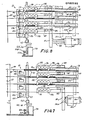
- FIG. 15 shows the schematic diagram, as a function of time, of the passage of the welding current 221, of the displacement of the mobile electrodes 154 relative to the contrast electrodes 157 and 171 and of the displacement of the units 43 or of the electrodes 171. Also shown , the movements of the clamps 127, of the operating members 122 and 123, of the wire 37 on the arms 105 as well as the movements of the arms 111.
- the following description relates to the planar assembly machine.
- the longitudinal wires 34 before their welding on the spacer wires 35, are unwound reels 240 (FIG. 1) of large capacity and are previously straightened, by means of a wire straightening machine 241.
- This machine of the type known, is not detailed here. It is generally provided with a series of rollers and counter-rolls of rectification 242 which straighten the wires.
- the wires are stiffened under the effect of the unwinding and deformations dms to. the torsion imprinted during this phase.
- the assembly machine 38 intended for trellis 36 comprises an elongated bench 245 having an entry area and an exit area 244.
- the bench 245 (FIG. 17) is provided with a series of crosspieces 246 capable of retaining the longitudinal wires 34.
- the wires longitudinal 34 are furthermore summarily held at predetermined reciprocal distances by suitable guides 247 movable along the crosspieces.
- alignment supports 246 carefully calibrated and of a length such that the longitudinal wires 34 come to be arranged substantially parallel to one another in a reference zone next to the support area to itself.
- the wires 34 lie substantially in the same plane; the reciprocal distance between the same wires is therefore very precise and has very low tolerances, compared to the project data.
- the device 250 is designed so that it can arrange each spacer wire 35 so as to cross the longitudinal wires 34, parallel to each other, so that each wire is as close as possible to or in contact with the wires 34 in their reference section.
- the device 250 (FIG. 18) comprises in particular a hopper 252 provided with an outlet channel 253 controlled by an operating member 254, a plurality of inclined bars 256 and a series of small stop wings 258.
- the welding unit 251 includes a fixed electrode 260, placed slightly below the wires 34 and transversely to the wires in their reference zone, and a group of mobile electrodes 261.
- the active part of these electrodes 261 is substantially parallel to the active part of the electrode 260, and the electrodes 261 are designed to move vertically relative to the electrode 260 under the action of the corresponding operating members 262,
- the electrodes 261, in their downward movement, are designed to cooperate with a spacer wire 35 and pushing it against the longitudinal wires 34 which, in turn, are stopped by the fixed electrode 260 in the respective crossing zones with a view to the successive welding of the wires 34 and 35.
- the machine 38 further comprises a advancement member 270 capable of advancing the longitudinal wires with respect to the electrodes 260 and 261 by a value perfectly equal to the pitch of the spacer wires.
- This device comprises transverse teeth 272 displaced by a chain 273 and capable of engaging the spacer wires 35 after their welding.
- the stroke of the teeth 272 is carefully controlled by an extension coder 275 which records exactly the angular displacements of an axis 276 on which is fixed a toothed wheel cooperating with the chain 271.
- This chain is, in turn, moved by a servo-mechanism comprising a motor 277 controlled by the extension coder in accordance with a program synchronized with the movement of the electrodes 261 and with the welding of the wires.
- a cutting device 278 actuated by a pneumatic control member 279 and comprising scissors capable of exactly cutting the spacer wire 35 adjacent to the weld zones with the longitudinal wires 34 located outside the lattice.
- the trellises themselves therefore have very precise dimensions, which allows a precise succession of the assembly operations of the structure 30 on the machine 40.
- the machine 38 makes it possible to assemble several trellises at the same time. This operation is carried out using a single transverse wire for several trellises. These are then separated during the same cutting phase following the welding.
- the different phases of advancement of the mesh, welding and cutting are controlled from a control unit 281 which comprises a microprocessor 282 (FIG. 19) and a control console 283. On the microprocessor 282 can be programmed and synchronized the different work stages, the progress stage and the welding times.
- FIG. 20 summarizes the different phases of assembly of the structure 30.
- phase 290 the welding and twisting of the wires 34, 35 and 37 are carried out, which will be cut respectively in phases 291, 292 and 293.
- the wires 34 are respectively placed on the supports 246 of the machine 38 and the wires 35 on the appropriate hopper 252.
- the wires 34 - and 35 are welded in phase 296 and then cut in phase 297.
- the trellis can be picked up in phase 299 and placed on the support planes 81 of the assembly machine 40.
- the transverse wires 37 will in turn be picked up in hoppers 101 during phase 211.
Abstract
L'invention concerne un procédé et une machine d'assemblage de structures métalliques tridimensionnelles, caractérisés par les étapes suivantes : a) réalisation d'une série de treillis plans (36) comprenant des fils longitudinaux (34) et des fils d'entretoise (35); b) placement des treillis sur des supports (81); c) alignement des treillis sur des éléments de repère; d) alignement des treillis sur les premiers éléments d'alignement; e) disposition d'au moins un fil transversal (37) dans une position telle que ce fil croise les fils longitudinaux (34) ou les fils d'entretoise (35); f) accès avec au moins une unité de soudure (43) à la zone de croisement des treillis (36) avec le fil transversal (37); g) exécution de la soudure des fils dans la zone de croisement; h) déplacement réciproaque des treillis et de l'unité de soudure; i) répétition des étapes f) à h) pour le nouveau fil transversal.The invention relates to a method and a machine for assembling three-dimensional metal structures, characterized by the following steps: a) production of a series of planar trellises (36) comprising longitudinal wires (34) and spacer wires ( 35); b) placing the trellis on supports (81); c) alignment of the trellis with reference elements; d) alignment of the trellis on the first alignment elements; e) provision of at least one transverse wire (37) in a position such that this wire crosses the longitudinal wires (34) or the spacer wires (35); f) access with at least one welding unit (43) to the area where the trellis (36) intersects with the transverse wire (37); g) carrying out the welding of the wires in the crossing zone; h) reciprocal movement of the trellis and the welding unit; i) repeating steps f) to h) for the new transverse wire.
Description
L'invention concerne un procédé d'assemblage de structures métalliques tridimensionnelles, à titre d'exemple pour des éléments préfabriqués tels que panneaux ou plafonds devant être utilisés dans la construction. L'invention concerne également les machines qui réalisent ce procédé et, enfin, la structure réalisée selon ce même procédé.The invention relates to a method of assembling three-dimensional metal structures, by way of example for prefabricated elements such as panels or ceilings to be used in construction. The invention also relates to the machines which carry out this process and, finally, to the structure produced according to this same process.
On connaît une structure tridimensionnelle en fils métalliques comprenant une série de treillis plans. Chaque treillis est pourvu d'au moins une paire de fils longitudinaux et de fils d'entretoise. Les treillis présentent des distances réciproques prédéterminées grâce à une série de fils transversaux soudés aux treillis mêmes et à des fils d'entretoise. Une telle structure forme des plans d'appui pour des corps allongés de dimensions correspondantes en matériel léger et isolant inséré. à l'intérieur de la structure elle-même. La production de ces structures exige une tolérance très faible des différents composants et un alignement méticuleux entre ces parties dans les phases de soudure. Pour répondre à ces exigences de nombreuses interventions manuelles pour porter les unités de soudure dans les zones de croisement des fils à souder et pour maintenir l'alignement entre les parties sont nécessaires. Un tel procédé est donc nécessairement coûteux. En outre, il est très difficile de réaliser en même temps l'alignement dans le même plan des fils d'entretoise des différentes sections de la structure. On a également rencontré de sérieux problèmes dans la réalisation de ces structures, en particulier au niveau de la fiabilité des soudures et de la résistance élevée aux sollicitations statiques et dynamiques de la structure.There is known a three-dimensional structure of metal wires comprising a series of planar trellises. Each trellis is provided with at least one pair of longitudinal wires and spacer wires. The trellises have predetermined reciprocal distances thanks to a series of transverse wires welded to the trellises themselves and to strut wires. Such a structure forms support planes for elongated bodies of corresponding dimensions made of inserted light and insulating material. inside the structure itself. The production of these structures requires very little tolerance of the different components and meticulous alignment between these parts during the welding phases. To meet these requirements, numerous manual interventions to carry the welding units to the crossing zones of the solder wire and to maintain alignment between the parts are required. Such a process is therefore necessarily expensive. In addition, it is very difficult to achieve at the same time the alignment in the same plane of the spacer wires of the different sections of the structure. Serious problems have also been encountered in the production of these structures, in particular with regard to the reliability of the welds and the high resistance to static and dynamic stresses of the structure.
Le problème technique concerné par la présente invention réside dans la réalisation d'un procédé d'assemblage simple et relativement peu coûteux permettant d'assembler un treillis tridimensionnel très précis en fils métalliques et d'une résistance élevée aux sollicitations. Ce problème peut être résolu par le procédé selon la présente invention, procédé caractérisé par les étapes suivantes :
- a) réalisation d'une série de treillis plans comprenant des fils longitudinaux et d'entretoise soudés aux fils longitudinaux;
- b) positionnement des treillis en accord avec un pas transversal donné;
- c) alignement des treillis de façon à amener les fils d'entretoise des différents treillis dans le même plan;
- d) alignement des fils longitudinaux d'au moins un côté des treillis de façon à définir des plans correspondants d'alignement de la structure;
- e) disposition d'au moins un fil transversal dans une position dans laquelle ce fil croise les fils longitudinaux ou les fils d'entretoise des treillis dans des zones différentes de croisement avec lesdits fils longitudinaux ou, respectivement, d'entretoise;
- f) accès avec au moins une unité de soudure à la zone de croisement des treillis avec le fil transversal de façon que les électrodes de ladite unité de soudure se trouvent face aux fils croisés dans la zone de croisement concernée;
- g) mise en contact réciproque des fils croisés et des électrodes et exécution de la soudure des fils dans la zone de croisement;
- h) déplacement réciproque des treillis et de l'unité de soudure d'une quantité égale au pas des fils transversaux, en maintenant les fils d'entretoise dans le même plan;
- i) répétition des étapes f) à h) pour le nouveau fil transversal et la nouvelle zone de croisement jusqu'à la soudure des fils longitudinaux avec les fils longitudinaux ou d'entretoise des treillis de la structure.
- a) production of a series of planar trellises comprising longitudinal wires and spacers welded to the longitudinal wires;
- b) positioning of the trellis in accordance with a given transverse pitch;
- c) alignment of the trellis so as to bring the spacer wires of the different trellises in the same plane;
- d) alignment of the longitudinal wires of at least one side of the trellis so as to define corresponding planes of alignment of the structure;
- e) arrangement of at least one transverse thread in a position in which this thread crosses the longitu threads dinaux or the strut wires of the trellis in different crossing zones with said longitudinal wires or, respectively, of strut;
- f) access with at least one welding unit to the crossover zone of the trellises with the transverse wire so that the electrodes of said welding unit are facing the crossed wires in the crossover zone concerned;
- g) reciprocal contacting of the crossed wires and of the electrodes and carrying out the welding of the wires in the crossing zone;
- h) reciprocal displacement of the mesh and the welding unit by an amount equal to the pitch of the transverse wires, keeping the spacer wires in the same plane;
- i) repeating steps f) to h) for the new transverse wire and the new crossing zone until the longitudinal wires are welded with the longitudinal wires or the struts of the trellis of the structure.
Suivant une autre caractéristique de l'invention, l'assemblage des treillis qui forment la structure tridimensionnelle prévoit les étapes suivantes :
- a) réalisation de fils droits à partir de dévidoirs, par redressement et, en même temps, torsion de ces fils;
- b) disposition d'un groupe de fils longitudinaux dans des supports d'alignement qui permettent la mise en position parallèle entre eux des fils susdits;
- c) soudure, dans les points de croisement respectifs, des fils longitudinaux avec un fil d'entretoise, de façon que les fils susdits soient substantiellement dans le même plan que le fil d'entretoise précité;
- d) avancement des fils longitudinaux par rapport aux supports d'alignement, d'une distance égale au pas desdits fils d'entretoise, de façon à définir une autre section de repère substantiellement égale à la section de repère précédente;
- e) disposition d'un deuxième fil d'entretoise de manière que celui-ci croise et soit proche ou soit en contact avec une autre section de repère desdits fils longitudinaux et de façon que ce fil se trouve à une distance exactement définie par rapport au fil d'entretoise précédent;
- f) soudure de l'autre fil d'entretoise aux fils longitudinaux dans les zones de croisement respectives;
- g) répétion des étapes d) à f) jusqu'à l'exécution de toutes les soudures du treillis.
- a) production of straight wires from reels, by straightening and, at the same time, twisting these wires;
- b) arrangement of a group of longitudinal wires in alignment supports which allow the aforementioned wires to be brought into parallel position;
- c) welding, in the respective crossing points, of the longitudinal wires with a spacer wire, so that the abovementioned wires are substantially in the same plane as the aforementioned spacer wire;
- d) advancement of the longitudinal wires with respect to the alignment supports, by a distance equal to the pitch of said spacer wires, so as to define another reference section substantially equal to the previous reference section;
- e) provision of a second spacer wire so that it crosses and is close to or is in contact with another reference section of said longitudinal wires and so that this wire is at a precisely defined distance from the previous spacer wire;
- f) welding of the other spacer wire to the longitudinal wires in the respective crossing zones;
- g) repeating steps d) to f) until all the welds in the trellis have been completed.
La structure tridimensionnelle réalisée selon le procédé suivant l'invention est caractérisée par une remarquable résistance aux sollicitations, grâce à la torsion des fils et à la précision des soudures. Cette structure est en outre caractérisée par une exactitude dans les plans des différents fils d'entretoise, afin d'obtenir des espaces très réduits entre les corps allongés insérés à l'intérieur de la structure elle-même. En outre, la structure assemblée présente une grande précision dimensionnelle afin de garantir une disposition optimale des panneaux lors de la réalisation des constructions.The three-dimensional structure produced according to the method according to the invention is characterized by a remarkable resistance to stresses, thanks to the twist of the wires and to the precision of the welds. This structure is further characterized by an accuracy in the planes of the different spacer wires, in order to obtain very reduced spaces between the elongated bodies inserted inside the structure itself. In addition, the assembled structure has great dimensional precision in order to guarantee an optimal arrangement of the panels during construction.
Ces caractéristiques de l'invention ressortiront clairement de la description qui sera donnée ci-après à titre d'exemple non limitatif en se référant aux figures ci-après:
- La figure 1 est une vue d'ensemble schématique des machines d'assemblage utilisées selon le procédé conforme à l'invention:
- la figure 2 est une vue, en perspective, d'une machine à assembler selon la figure 1;
- la figure 3 est une vue en plan schématique et partielle, de la machine selon la figure 2;
- la figure 4 est une vue latérale de la machine selon la figure 3,en position de fonctionnement;
- la figure 5 représente une vue de face des détails de la machine selon la figure 2;
- la figure 6 représente des détails de la figure 5, dans une phase de fonctionnement;
- la figure 7 est une vue latérale des éléments de la machine selon la figure 2;
- la figure 8 représente des détails de la figure 7,dans une phase de fonctionnement;
- la figure 9 est une vue schématique, selon la coupe IX-IX, de la figure 4;
- la figure 10 représente une section schématique de détails de la machine selon la figure 2;
- la figure 11 est une vue schématique d'un autre détail de la machine selon la figure 2;
- la figure 12 est une vue en plan d'une variante d'un détail de la machine selon la figure 2;
- la figure 13 est une vue latérale schématique de la variante selon la figure 12;
- la figure 14 représente dans une phase de fonctionnement les éléments selon la figure 12;
- la figure 15 représente un diagramme de fonctionnement de la machine selon la figure 2;
- la figure 16 représente un schéma de l'ensemble de la machine selon la figure 2;
- la figure 17 est une vue schématique en plan d'une deuxième machine selon la figure 1;
- la figure 18 est une vue latérale schématique de la machine selon la figure 17;
- la figure 19 est un schéma par groupes de la machine selon la figure 17;
- la figure 20 est un schéma par groupes généraux des-opérations intervenant dans le procédé selon l'invention.
- FIG. 1 is a schematic overview of the assembly machines used according to the method according to the invention:
- Figure 2 is a perspective view of an assembly machine according to Figure 1;
- Figure 3 is a schematic and partial plan view of the machine according to Figure 2;
- Figure 4 is a side view of the machine according to Figure 3, in the operating position;
- 5 shows a front view of the details of the machine according to Figure 2;
- FIG. 6 shows details of FIG. 5, in an operating phase;
- Figure 7 is a side view of the elements of the machine according to Figure 2;
- FIG. 8 shows details of FIG. 7, in an operating phase;
- Figure 9 is a schematic view, along section IX-IX, of Figure 4;
- Figure 10 shows a schematic section of details of the machine according to Figure 2;
- Figure 11 is a schematic view of another detail of the machine according to Figure 2;
- Figure 12 is a plan view of a variant of a detail of the machine according to Figure 2;
- Figure 13 is a schematic side view of the variant according to Figure 12;
- Figure 14 shows in a phase of operation of the elements according to FIG. 12;
- FIG. 15 represents a diagram of the operation of the machine according to FIG. 2;
- Figure 16 shows a diagram of the whole machine according to Figure 2;
- Figure 17 is a schematic plan view of a second machine according to Figure 1;
- Figure 18 is a schematic side view of the machine according to Figure 17;
- Figure 19 is a block diagram of the machine according to Figure 17;
- FIG. 20 is a diagram by general groups of the operations involved in the method according to the invention.
Le procédé d'assemblage selon l'invention est destiné à réaliser, par exemple mais non exclusivement, des structures métalliques tridimensionnelles 30 (figure 2) du genre décrit dans la demande de brevet européen n° 82102021 publiée le 29.9.82. Ce procédé a pour but , en particulier, d'assembler des treillis plans 36 réalisés en fils d'acier avec des fils transversaux 37 et prévoit, de préférence, l'utilisation d'une machine permettant l'assemblage de la structure tridimensionnelle 40.The assembly method according to the invention is intended to produce, for example but not exclusively, three-dimensional metallic structures 30 (FIG. 2) of the kind described in European patent application No. 82102021 published on September 29, 82. The aim of this process is, in particular, to assemble
Les treillis 36 comprennent des fils longitudinaux 34 et des fils d'entretoise 35 et sont, dans une phase antérieure à celle qui consiste à assembler la structure tridimensionnelle, réalisésau moyen d'une soudeuse plate 38 (figure 1).The
La machine d'assemblage 40 (figure 2) comprend une structure de support 41 qui soutient les treillis 36, un groupe d'alimentation 42 à partir duquel sont prélevés les fils transversaux 37 pour être soudés aux treillis 36, une série d'unités de soudure 43 et un groupe d'avancement 45 pour la structure 30, au cours de l'assemblage, et un ensemble de collecte 50 (figure 1).The assembly machine 40 (FIG. 2) comprises a
La machine prévoit en outre un groupe électronique 57 (figure 10) pour la commande séquentielle des différentes phases d'assemblage et de soudure, une console de commande 58 , une unité pneumatique 59 pour la réalisation des commandes ou ordres envoyés par l'unité 58 et une unité hydraulique 60 pour le refroidissement des électrodes de soudure des machines d'assemblage 38 et 40.The machine also provides an electronic group 57 (FIG. 10) for the sequential control of the various assembly and welding phases, a
La description qui suit vise la structure de soutien.The following description relates to the support structure.
La structure de soutien 41 comporte un groupe de montants 79 sur lesquels sont fixées à des distances prédéterminées, par paires, une série de traverses 80. Les traverses 80 soutiennent à leur tour,une série de plans d'appui 81 horizontaux et superposés. Les distances entre les plans 81 sont égales entre elles et règlent le pas transversal des treillis plans 36 par rapport à la structure 30 déjà assemblée.The
Les plans 81 (figure 3) sont de forme rectangulaire très allongée et sont pourvus de deux côtés latéraux 82 et 83 , respectivement gauches et droites , si l'on se réfère à la figure 4, et soutiennent un treillis correspondant plan 36.The planes 81 (FIG. 3) are of very elongated rectangular shape and are provided with two
Un élément de contrôle 83, formé d'un tréfilé de section rectangulaire, est fixé à chaque côté 82 et est pourvu d'une surface de contrôle 85 capable de collaborer avec les extrémités, à gauche àla figure, des fils d'entretoise 35 des treillis 36. Les surfaces 85 des éléments de contrôle 83 des différents plans 81 sont situées dans le même planet définissent une surface de repère verticale de la structure tridimensionnelle 30.A
Un autre élément de contrôle 86, constitué également d'un tréfilé de section rectangulaire, est fixé, de façon réglable au coté 83 de chaque plan 81 et est pourvu d'une surface 87 avec laquelle peuvent collaborer les extrémités, à droite à la figure, des fils d'entretoise 35 des treillis 36. Les surfaces 87 des éléments de contrôle 86 sont situées dans le même plan et définissent un autre plan de repère vertical de la structure tridimensionnelle 30, parallèle au plan vertical défini par les surfaces 85.Ces deux plans de repère sont tels qu'ils amènent les fils longitudinaux 34 dans le même plan, du même côté des différents treillis 36 et sont, en outre, perpendiculaires aux plans des mêmes treillis 36. Sur une extrémité, à la partie antérieure,selon la figure 3, des éléments de contrôle 85 et 86, sont fixés des éléments de guidage 92 et 93 formés de tréfilés de section en U faisant saillie hors des plans 81. Ces éléments collaborent avec les extrémités des fils d'entretoise 35 ainsi qu'avec les fils longitudinaux 34 des treillis plans 36 et servent à définir avec précision les plans verticaux de repère de la structure 30 et à éviter le gauchissement des treillis 36 dans la zone proche de l'extrémité de sortie des éléments de guidage 92 et 93, adjacents aux unités de soudure 43.Another
Les éléments de contrôle 87 et les éléments de guidage 93 sont déplaçables par rapport aux côtés 83, par exemple à l'aide de vis 94. De cette façon, la distance entre plans de repère des surfaces 87 et les éléments de guidage 92 peut être modifiée soit par rapport au plan de repère des surfaces 85, soit par rapport aux éléments de guidage 93, pour définir exactement les plans de repère verticaux des structures 30 utilisant des treillis 36 de différentes largeurs.The
Un groupe d'alimentation fait suite à la structure de soutien. Ce groupe d'alimentation 42 est divisé en deux unités, dont chacune comprend une trémie 101 (figure 2) dans laquelle sont disposés telsquelsdes fils transversaux 37. Les fils pénètrent par gravité dans un canal de sortie 102 (figure 11) et cette opération est facilitée par l'action d'un excentrique 103. Un dispositif 104 est ménagé pour laisser tomber un à un les fils 37 qui, après avoir été guidés par les barres inclinées 105, s'arrêtent à la base des barres 105,en butant contre des épaulements 106. La présence du fil 37, retenu contre les épaulements 106, est détectée par un signaleur magnétique 107 qui transmet , sous forme de signaux électriques, les infornations en question à l'unité de contrôle 57.A feeding group follows on from the support structure. This
Entre le support 41 et les trémies 101 (figure 3) sont prévus deux bras de prise lll, formés chacun par une barre parallélépipédique avec un point d'appui à une extrémité et un arbre de sortie 112 d'un organe de manoeuvre pneumatique 113. Cet organe de manoeuvre l13 est prévu pour faire tourner le bras de prise d'une position horizontale vers une position verticale. Chaque bras de prise 111 est, dans sa position horizontale, substantiellement aligné et superposé au fil 37 temporairement arrêté contre les épaulements 106 et à proximité du fil même. Un nombre d'aimants 114 sont disposés pour écarter le fil 37 des épaulements 106 et pour le maintenir sur le bras 111 en alignement avec l'axe du même bras.Between the
Cette position reste inchangée même lorsque le bras 111 est en position verticale. Deux senseurs 115 et 116 ont, en outre, pour tâche de détecter respectivement la position horizontale et la position verticale du bras 111 et de transmettre l'information à l'unité de contrôle 57.This position remains unchanged even when the arm 111 is in the vertical position. Two
Face à la trémie 101 (figures 2 et 3), sont disposés deux organes de manoeuvre pneumatiques 121, pourvus de pistons 122, mobiles dans un plan horizontal suivant une direction perpendiculaire aux plans de repère des surfaces 85 et 86. Sur les pistons 122 sont fixés deux blocs de support correspondants 123 sur lesquels sont fixés à leur tour deux autres organes de manoeuvre pneumatiques 124. Ces organes de manoeuvre 124 sont pourvus de pistons 125 qui sont mobiles horizontalement suivant une direction inclinée de 45° par rapport aux plans de repère des surfaces 85 et 86. Les pistons 125 supportent deux montants 126 auxquels sont fixées deux séries correspondantes de pinces 127 , à fonctionnement pneumatique, capables d'écarter les fils 37 des bras 111 et à les maintenir parallèlement aux montants 126. Des senseurs 128 permettent de détecter la présence d'un ou de plusieurs fils 37 retenus par les pinces 127. Les supports 123 peuvent être écartés des pistons 122 depuis des positions latérales à proximité des trémies vers de positions centrales voisines des unités de soudure 43 et des éléments de guidage 92 et 93. Les montants 126 peuvent, à leur tour, être écartés des pistons 125 à partir de positions éloignées des trémies 101 et des éléments de guidage 92 et 93 vers des zones proches des bras 111, disposés en position verticale, et des unités de soudure 43.Facing the hopper 101 (FIGS. 2 and 3), are arranged two
Des senseurs de fin de course 131 et 132 des organes de manoeuvre 121 détectent respectivement les positions latérales et centrales des blocs 123 et des senseurs de fin de course 133 des organes de manoeuvre 124 détectent les positions des montants 126 à proximité des bras 111 et des unités de soudure 43. En outre, des senseurs magnétiques 134 détectent la présence des fils 37 sur les montants 126, alors qu'ils sont maintenus par des pinces 127. Les informations des senseurs 134 sont également transmises à l'unité de contrôle 57. Les trémies 101 sont disposées pour accepter chacune, avec des éléments de séparation appropriés, deux séries de fils transversaux 37, d'une longueur à peine inférieure à la largeur maximale de la trémie elle-même. Les barres inclinées 105, les bras de prise 111, les montants 126, les pinces 127 et les différents senseurs sont capables de traiter à la fois deux fils 37 alignés entre eux et proches l'un de l'autre. Ceci permet d'assembler en même temps deux structures tridimensionnelles ayant une hauteur légèrement inférieure à la moitié d'une structure de hauteur maximale.End-of-
Les unités de soudure 43 (figure 3) sont divisées en deux groupes montés respectivement sur deux plaques 145 et 146. Ces plaques sont montées à glissement sur des montants verticaux 147 disposés à gauche et à droite des éléments de guidage 92 et 93 de façon qu'à chaque paire d'éléments 92 et 93 soit associée une paire d'unités de soudure 43.The welding units 43 (FIG. 3) are divided into two groups mounted respectively on two
Chaque unité 43 comprend un corps 151 en forme de parallélépipède creux, sur lequel sont montés un transformateur 152, un organe de manoeuvre pneumatique 153, une électrode mobile 154 et une électrode de contraste 155.Each
L'électrode mobile 154 est fixée à un piston 157 de l'organe de manoeuvre 153 qui, à son tour, est guidé par des douilles l'isolant du corps 151. L'électrode de contraste 155 a une corps en forme de L et est connectée électriquement au corps 151. Le transformateur 152 est inséré partiellement dans le corps parallélépipédique 151 et est pourvu d'un primaire dont les terminaux peuvent être connectés au réseau. Le - secondaire du transformateur est pourvu de deux terminaux 159 et 160 connectés aux électrodes 154 et 155. Le terminal 159 est directement connecté à l'électrode 155, tandis que le raccord entre l'électrode 154 et le terminal 160 est assuré par une série de fines lames de cuivre, repliées en forme de U, qui permettent les déplacements du piston 157 par rapport au transforma- teur 152. La partie active de chaque électrode mobile 154 (figure 5) indiquée par 163, est de forme cylindrique et est disposée plus haut par rapport au piston 157, elle est connectée à celui-ci par un bloc 164. La partie active de chaque électrode 155, indiquée par 165, a la forme d'un parallélépipède et dépasse vers le haut l'électrode 155.Les blocs 164 des électrodes 154 et 155 sont traversés intérieurement par des canalisations de refroidissement, pourvues de petites embouchures d'entrée et de sortie 166 et 167 reliées à l'unité hydraulique 60.The
En position de repos, les parties 163 et 165 des unités 43 sont disposées en dessous des plans des treillis 35 et chaque plaque 145, 146 est déplaçable verticalement par rapport aux montants 147. Un organe de manoeuvre 170 déplace vers le haut les unités de soudure 43 pour amener les parties 163 et 165 en alignement avec les plans des treillis 35. En outre, deux senseurs de fin de course 168 et 169 peuvent détecter, respectivement, les positions haute et basse des unités 43. Dans la variante selon les figures 12 et 13, les unités de soudure 43 sont montées sur deux plaques fixes 180. Chaque électrode de contraste, désignées par 171, est pourvue d'un bras de levier 173 et pivote autour d'une douille 172 parallèlement au piston 157. Les parties actives 163 des électrodes mobiles 154 sont mises en alignement avec les plans des divers treillis 36, tandis que les parties actives des électrodes 171 sont disposées en dessous de ces plans. Les bras 173 pivotent sur une bielle verticale unique 174 laquelle est, à son tour, reliée à un organe de manoeuvre pneumatique 175.In the rest position, the
L'organe de manoeuvre 175 est conçu pour faire pivoter les électrodes 171 autour des douilles 172 de façon à porter les parties actives 164 en alignement avec les plans des treillis 36. Les senseurs 168 et 169 détectent, dans ce cas, les positions respectivement haute et basse des électrodes 171.The actuator 175 is designed to pivot the
Le groupe 45, dénommé groupe d'avancement (figures 3 et 7) comprend un organe de manoeuvre pneumatique 182 pourvu de deux pistons 183 qui peuvent être déplacés parallèlement aux éléments de guidage 92 et 93. Sur les pistons 183 est montée une barre verticale 184 à laquelle sont fixés des bras horizontaux 185 en forme de L et disposés dans l'espace compris entre les plans des treillis 36. Les bras 185 ont une partie longitudinale 186 disposée dans le plan moyen entre les plans verticaux de repère définis par les éléments de guidage 92 et 93.The
Sur chaque partie 186 pivote, au moyen d'un pivot 187, un levier denté 190, pourvu inférieurement d'une dent antérieure 191 et d'une dent postérieure 192. En position de repos, le levier 190 est maintenu en position horizontale par gravité et contre l'action d'un élément d'arrêt 188 de la partie 186. Chaque dent 191, 192, dans sa partie antérieure, comprend un bord correspondant de rencontre 193 substantiellement vertical et, dans sa partie postérieure, un bord incliné 194. Les bords de rencontre 193 des dents 191 et 192 sont alignés entre eux sur deux plans verticaux dont la distance est légèrement supérieure (à peu près 1 mm pour des fils métalliques de 0,6 - 0,7 mm) à la moitié du pas des fils d'entretoise 35 et des treillis 36. L'organe de manoeuvre 182 est conçu pour déplacer la barre 184, et donc les leviers 190 d'un trajet égal à la moitié du pas des fils d'entretoise 35. Une paire de senseurs de fin de course 197 et 196 vérifie avec précision les limites de fin de course et transmet les informations à l'unité de contrôle 57. Les bords de contrôle 193 sont conçus pour collaborer avec les fils d'entretoise 35 en vue de déplacer en même temps les treillis 36, tout en gardant le même plan des fils d'entretoise des différents treillis 36, soit avant l'assemblage de la structure 30, soit pendant le déplacement des treillis 36, au cours des opérations de soudure.On each
Particulièrement, en position de repos, les bords de contrôle 193 des dents 191 ou 192 sont disposés à proximité des fils et derrière les fils d'entretoise 35 des treillis 36. Par conséquent, lors d'un déplacement en avant des pistons 183, les bords 193 des dents 191, ou des dents 192, des leviers 190 entraînent les treillis 36 vers la partie antérieure de la machine, et cela d'une course égale à la moitié du pas des fils d'entretoise 35.Particularly, in the rest position, the control edges 193 of the
Pendant la course de retour, les fils d'entretoise 35, avec les bords inclinés 194, provoquent le soulèvement des leviers dentés 190 qui peuvent ainsi ramener à nouveau les bords 193 derrière les fils d'entretoise 35 en vue d'un nouvel avancement des treillis 36. Au cours des deux cycles de déplacement vers l'avant et vers l'arrière des leviers 190, les dents 191 et 192 n'agissent qu'une seule fois, mais dans les deux cycles sur un même fil d'entretoise 35. On réalise ainsi un pas des fils transversaux 37 substantiellement égal à la moitié du pas des fils d'entretoise 35 sur la structure 30 déjà assemblée.During the return stroke, the
En se référant à la figure 1, on remarquera que l'ensemble de collecte 50 comprend un plan de renversement 201 pourvu d'une base 202 pour ramasser la structure déjà assemblée et au moins une zone 203 capable de recevoir une console pour-.une deuxième. structure quand la machine d'assemblage 40 assemble en même temps deux structures de hauteur réduite.Referring to FIG. 1, it will be noted that the
L'unité 57, dite unité de contrôle, comprend un microprocesseur 210 pourvu d'une série d'unités d'interfaces d'entrée-sortie. Les interfaces d'entrée reçoivent les données des senseurs détectant la présence des fils et des senseurs détectant la fin de course des organes de manoeuvre; les unités d'interface de sortie sont connectées à des relais, éventuellement, à des interrupteurs statiques qui commandent l'ouverture ou la fermeture de vannes 212-219, insérées entre le circuit d'air comprimé 225 de l'unité pneumatique 59 et, respectivement, des organes de manoeuvre 104, 113, 122, 124, 127, 182, 169 ou 175 ainsi que de tous les organes de manoeuvre 153 des unités de soudure 43.The
Le microprocesseur 210 est prévu pour activer une unité de puissance 226 qui connecte au réseau les primaires des transformateurs 152 des unités 43. Le microprocesseur 210 est doté d'un programme qui commande la réalisation des différentes électro-vannes dans un ordre prédéterminé et en fonction de l'état des différents senseurs. Il est en outre connecté à une série d'organes de réglage pour permettre une variation dans les temps de soudure.The
Le procédé d'assemblage est schématisé à la figure 20 et est conçu pour réaliser aux phases 211 et 212, la collecte des fils 37 dans les trémies 101 et le positionnement des treillis 36 (figure 3) sur les plans d'appui 81. On engage donc les fils longitudinaux 34 dans les divers éléments de guidage 92 et 93 jusqu'à ce que les fils d'entretoise 35 de la première série se trouvent placés devant les bords de contrôle 193 des dents 191.The assembly process is shown diagrammatically in FIG. 20 and is designed to carry out in
La machine 40 est conçue pour travailler avec deux fils 37, ou quatre fils dans le cas où sont assemblées deux structures déjà positionnés sur les bras 111 et cela en position verticale. Les blocs 123 se trouvent dans les positions latérales respectives et les montants 126 sont éloignés des bras 111. A ce stade, l'unité de contrôle 57 est prête à entamer l'assemblage de la structure 30. En actionnant la touche de démarrage, on met en marche les organes de manoeuvre 182 qui déplacent les leviers respectifs 190 en direction de la partie antérieure de la machine, faisant ainsi avancer simultanément les treillis 36 non encore assemblés. Par conséquent, pendant que les fils d'entretoise 35 de la première série sont correctement mis en place dans un même plan, les fils longitudinaux 34 sont amenés dans les zones de soudures respectives.The
Après le déplacement vers l'avant des treillis 36 détectés par les senseurs 198, l'unité de contrÔle 57 met en marche les organes de manoeuvre 124 pour amener les montants 126 à proximité des bras 111. L'unité 57 commande la fermeture des pinces 127 sur les fils 37 et la reprise des fils sur les montants 126. Cet état de choses étant vérifié, l'unité 57 prévoit la mise en fonctionnement, du coté opposé, des organes de manoeuvre 124, en éloignant les montants 126, et donc les fils, des bras 111. L'unité 57 met en marche les organes de manoeuvre 121 pour déplacer les blocs de support 123 vers la zone de soudure.After moving the
L'unité de contrôle 57, après avoir vérifié, grâce aux senseurs 131, la nouvelle position des éléments actionne à nouveau les organes de manoeuvre 124 (figure 15), pour porter les fils 37 à proximité immédiate des fils longitudinaux 34. Attendu que les pistons 125 se déplacent sous un angle de 45° par rapport aux axes des électrodes et des fils 34, les fils 37 et les montants 126 peuvent se déplacer librement sans former obstacle à ces pièces. La nouvelle position des fils 37 est détectée par les senseurs 133. L'unité 57 réalise, à ce stade, le relèvement des plaques 145 et 146, ainsi que de toutes les unités de soudure 43, ou les bielles verticales 174 (figure 13) avec les seules électrodes 171,jusqu'à porter les parties actives 163 et 165 (figure 5) des électrodes en alignement avec les fils longitudinaux 43 et en axe avec les zones de croisement des fils transversaux 37 avec les fils longitudinaux 34. L'unité 57 prévoit en outre le fonctionnement des organes de manoeuvre 113 pour amener les bras 111 en position horizontale pour permettre le prélèvement d'une autre paire de fils 37 (ou de quatre fils, dans le cas de deux structures) hors des trémies 101.The
Au cours de l'étape suivante, l'unité 57 prévoit la commande de tous les organes de manoeuvre 153 de toutes les unités de soudure 43. Par conséquent, les électrodes mobiles 154 amènent les fils croisés 34 et 37 au contact des électrodes de contraste respectives. L'unité 57 prévoit donc l'alimentation des primaires des transformateurs 152 et la soudure des fils 37 et 34 dans les zones de croisement respectives. Alors que les électrodes maintiennent encore les fils 34 et 37, l'unité 57 met en marche les organes de manoeuvre 182 en vue d'une course de retour vers la partie postérieure de la machine. Les leviers 190 sont donc retirés vers l'arrière et dépassent légèrement, par leurs dents postérieures 192, les fils d'entretoise 35 de la deuxième série. La nouvelle position des leviers 190 ayant été vérifée au moyen des senseurs 197,l'unité 57 commande l'ouverture des électrodes et des pinces et commande en sens opposé les organes de manoeuvre 180 ou 175 pour porter les électrodes hors du trajet des fils d'entretoise 35. L'unité 57 ramène en outre les bras 111 en position verticale. L'unité 57 éloigne enfin les montants 126 et les blocs 123 de la zone de soudure,ramenant la machine dans sa position de départ.During the next step, the
La figure 3 montre, en points-tirets, la position des blocs 123 à proximité de la zone de soudure, les pinces 127 étant représentées ouvertes, et à l'écart de la zone de soudure. Les positions avancées des leviers dentés 190 et des treillis 36 sont représentées de la même manière. La figure 4 montre la disposition des organes de manoeuvre 121 et 124 en vue de la phase de soudure, les fils 35 étant alignés par les leviers dentés 190. La figure 8 montre les positions occupées par l'unité 43 pendant la phase de soudure et, en points-tirets, la phase de reprise d'un fil 35 par une dent 192.Figure 3 shows, in dashed lines, the position of the
La figure 15 montre le diagramme schématique, en fonction du temps, du passage du courant de soudure 221, du déplacement des électrodes mobiles 154 par rapport aux électrodes de contraste 157 ou 171 et du déplacement des unités 43 ou des électrodes 171. Sont aussi représentés, les déplacements des pinces 127, des organes de manoeuvre 122 et 123, du fil 37 sur les bras l05 ainsi que les déplacements des bras 111.FIG. 15 shows the schematic diagram, as a function of time, of the passage of the welding current 221, of the displacement of the
La description qui suit concerne la machine d'assemblage plane.The following description relates to the planar assembly machine.
Les fils longitudinaux 34, avant leur soudure sur les fils d'entretoise 35, sont déroulés des dévidoirs 240 (figure 1) de grande capacité et sont préalablement redressés, au moyen d'une machine à dresser les fils 241. Cette machine, de type connu, n'est pas détaillée ici. Elle est, d'une manière générale, pourvue d'une série de rouleaux et de contre- rouleaux de rectification 242 qui redressent les fils.The
Au cours du redressement, les fils sont raidis sous l'effet du déroulement et des déformations dms à. la torsion imprimée au cours de cette phase.During the straightening, the wires are stiffened under the effect of the unwinding and deformations dms to. the torsion imprinted during this phase.
La machine d'assemblage 38 destinée aux treillis 36 comprend un banc allongé 245 ayant une zone d'entrée et une zone de sortie 244. Le banc 245 (figure 17) est pourvu d'une série de traverses 246 capables de retenir les fils longitudinaux 34. A leur tour, les fils longitudinaux 34, sont en outre tenus sommairement à distances réciproques prédéterminées par des guides appropriés 247 déplaçables le long des traverses. Dans la zone médiane du banc 245 sont., en outre, prévus des supports d'alignement 246 soigneusement calibrés et d'une longueur telle que les fils longitudinaux 34 viennent à être disposés substantiellement parallèlement entre eux dans une zone de repère à côté de la zone des supports aux-mêmes. Les fils 34 se trouvent substantiellement dans le même plan; la distance réciproque entre les fils mêmes est donc très précise et présente de très faibles tolérances, par rapport aux données du projet. A côté de la zone de sortie des supports 248, sont prévus un dispositif 250 pour l'alimentation des fils d'entretoise 35 et une unité de soudure 251. Le dispositif 250 est conçu pour qu'il puisse disposer chaque fil d'entretoise 35 de manière à croiser les fils longitudinaux 34, parallèles entre eux, de telle sorte que chaque fil soit aussi près que possible des ou en contact avec les fils 34 dans leur section de repère. Le dispositif 250 (figure 18) comprend en particulier une trémie 252 pourvue d'un canal de sortie 253 contrôlé par un organe de manoeuvre 254, une pluralité de barres inclinées 256 et une série de petites ailes d'arrêt 258.The
L'unité de soudure 251 comprend une électrode fixe 260, disposée légèrement en dessous des fils 34 et transversalement aux fils dans leur zone de repère, et un groupe d'électrodes mobiles 261.La partie active de ces électrodes 261 est substantiellement parallèle à la partie active de l'électrode 260, et les électrodes 261 sont conçues pour se déplacer verticalement par rapport à l'électrode 260 sous l'action des organes de manoeuvre correspondants 262, Les électrodes 261, dans leur mouvement vers le bas, sont conçues pour coopérer avec un fil d'entretoise 35 et à pousser celui-ci contre les fils longitudinaux 34 lesquels, à leur tour, sont arrêtés par l'électrode fixe 260 dans les zones de croisement respectives en vue de la soudure successive des fils 34 et 35. La machine 38 comprend en outre un organe d'avancement 270 capable de faire avancer les fils longitudinaux par rapport aux électrodes 260 et 261 d'une valeur parfaitement égale au pas des fils d'entretoise. Ce dispositif comprend des dents transversales 272 déplacées par une chaîne 273 et capables d'engager les fils d'entretoise 35 après leur soudure. La course des dents 272 est soigneusement contrblée par un codificateur d'extension 275 qui relève exactement les déplacements angulaires d'un axe 276 sur lequel est fixée une roue dentée coopérant avec la chaîne 271. Cette chaîne est, à son tour, déplacée par un servo-mécanisme comprenant un moteur 277 contrblé par le codificateur d'extension en accord avec un programme synchronisé avec le mouvement des électrodes 261 et avec la soudure des fils. En aval du dispositif 250 est prévu un dispositif de coupe 278 actionné par un organe de commande pneumatique 279 et comprenant des ciseaux capables de couper exactement le fil d'entretoise 35 adjacent aux zones de soudure avec les fils longitudinaux 34 situés à l'extérieur du treillis. Les treillis mêmes ont donc des dimensions très précises, ce qui permet une succession précise des opérations d'assemblage de la structure 30 sur la machine 40.The
La machine 38 permet d'assembler en même temps plusieurs treillis. Cette opération est réalisée en utilisant un fil transversal unique pour plusieurs treillis. Ces derniers sont ensuite séparés au cours de la même phase de coupe qui suit la soudure. Les différentes phases d'avancement des treillis , de soudure et de coupe sont commandées à partir d'une unité de commande 281 qui comprend un microprocesseur 282 (figure 19) et une console de commande 283. Sur le microprocesseur 282 peuvent être programmés et synchronisés les différentes étapes de travail, l'étape d'avancement et les temps de soudure. La figure 20 résume les différentes phases d'assemblage de la structure 30.The
Dans la phase 290 sont réalisées la soudure et la torsion des fils 34, 35 et 37 qui seront coupés respectivement dans les phases 291, 292 et 293. Au cours des phases 294 et 295, on place respectivement les fils 34 sur les supports 246 de la machine 38 et les fils 35 sur la trémie appropriée 252. Les fils 34 - et 35 sont soudés dans la phase 296 et ensuite coupés dans la phase 297. Ensuite, alors que les dents transversales 272 reviennent vers la zone de soudure au cours de la phase 298, les treillis peuvent être ramassés en phase 299 et placés sur les plans d'appui 81 de la machine d'assemblage 40. Les fils transversaux 37 seront à leur tour ramassés dans les trémies 101 pendant la phase 211.In
A partir d'ici a lieu la phase d'assemblage de la structure 30 qui prévoit l'avancement pas à pas des fils transversaux dans la phase 300, pendant que l'organe de manoeuvre 104 et les bras 111 ont disposé le fil 37 en position médiane dans la phase 303.From here takes place the assembly phase of the
Suit alors le relèvement des électrodes en phase 305, la soudure en phase 306 et le retour des leviers 190 en phase 307. L'ordre d'abaisser les électrodes est donné ensuite en phase 309 et en phase 310 a lieu la collecte, sur le corps 50, de la structure assemblée.Then follows the raising of the electrodes in
Claims (35)
Priority Applications (35)
| Application Number | Priority Date | Filing Date | Title |
|---|---|---|---|
| AT84870056T ATE39070T1 (en) | 1984-04-24 | 1984-04-24 | PROCESS FOR ASSEMBLING THREE-DIMENSIONAL STRUCTURES FROM METAL WIRE, AND MACHINE FOR CARRYING OUT THE PROCESS. |
| DE8484870056T DE3475487D1 (en) | 1984-04-24 | 1984-04-24 | Method of assembling three-dimensional metal wire structures, and machine for carrying out the method |
| EP84870056A EP0162183B1 (en) | 1984-04-24 | 1984-04-24 | Method of assembling three-dimensional metal wire structures, and machine for carrying out the method |
| IN279/MAS/85A IN164625B (en) | 1984-04-24 | 1985-04-11 | |
| ZA852713A ZA852713B (en) | 1984-04-24 | 1985-04-11 | Method for assembling three-dimensional metal structures,machine for the manufacturing thereof,and structures obtained with such a method |
| IL74903A IL74903A (en) | 1984-04-24 | 1985-04-15 | Method for assembling three-dimensional metal structures,machine for the manufacturing thereof,and structures obtained with such a method |
| AU41260/85A AU586424B2 (en) | 1984-04-24 | 1985-04-15 | Method for assembling three-dimensional mental structures, machine for the manufacturing thereof, and structures obtained with such a method. |
| IE955/85A IE56375B1 (en) | 1984-04-24 | 1985-04-16 | Method for assembling three-dimensional metal structures,and machine for the manufacturing thereof |
| MA20634A MA20410A1 (en) | 1984-04-24 | 1985-04-17 | METHOD OF ASSEMBLING THREE-DIMENSIONAL METAL STRUCTURE, MACHINE FOR THEIR PRODUCTION AND STRUCTURES MADE ACCORDING TO THIS PROCESS. |
| NZ211819A NZ211819A (en) | 1984-04-24 | 1985-04-17 | Assembling three-dimensional wire mesh structures from plane wire nettings |
| CS852853A CS276338B6 (en) | 1984-04-24 | 1985-04-18 | Apparatus for the production of three-dimensional metallic structures |
| DK179385A DK167310B1 (en) | 1984-04-24 | 1985-04-22 | PROCEDURES FOR THE PLANT FOR MANUFACTURING THREE-DIMENSIONAL METAL STRUCTURES |
| EG252/85A EG17553A (en) | 1984-04-24 | 1985-04-22 | Method for assembling three-dimensional metal structures for the manufacturing thereof and structures obtained with such a method |
| US06/725,655 US4667707A (en) | 1984-04-24 | 1985-04-22 | Method for assembling three-dimensional metal structures, machine for the manufacturing thereof, and structures obtained with such a method |
| BR8501975A BR8501975A (en) | 1984-04-24 | 1985-04-23 | ASSEMBLY PROCESS OF THREE-DIMENSIONAL METALLIC STRUCTURES, MACHINE FOR ITS REALIZATION AND STRUCTURES OBTAINED ACCORDING TO THE PROCESS |
| PT80331A PT80331B (en) | 1984-04-24 | 1985-04-23 | METHOD OF ASSEMBLY OF THREE-DIMENSIONAL METAL STRUCTURES MACHINE FOR ITS REALIZATION AND STRUCTURES CARRIED OUT BY THIS PROCESS |
| FI851607A FI84328C (en) | 1984-04-24 | 1985-04-23 | Method and machine for assembling three-dimensional metal constructions |
| GR850987A GR850987B (en) | 1984-04-24 | 1985-04-23 | |
| SU853913952A RU2012433C1 (en) | 1984-04-24 | 1985-04-23 | Method for assembling three-dimensional metal constructions and machine for effecting the same |
| CA000479880A CA1291323C (en) | 1984-04-24 | 1985-04-23 | Method for assembling three dimensional metal structures, machine for the manufacturing thereof, and structures obtained with such a method |
| NO851613A NO179402C (en) | 1984-04-24 | 1985-04-23 | Process and plant for the manufacture of three-dimensional metallic structures |
| DD85275469A DD243652A5 (en) | 1984-04-24 | 1985-04-23 | METHOD FOR CONNECTING METALLIC, THREE-SENSATIONAL STRUCTURES. MACHINE FOR ITS IMPLEMENTATION AND STRUCTURES MANUFACTURED BY THIS PROCESS |
| DZ850086A DZ774A1 (en) | 1984-04-24 | 1985-04-23 | Method of assembling three-dimensional metal structures, machine for their production and structures produced according to this method. |
| AR85300164A AR242521A1 (en) | 1984-04-24 | 1985-04-23 | A machine for assembling three-dimensional metallic structures. |
| ES542473A ES8700095A1 (en) | 1984-04-24 | 1985-04-23 | Method of assembling three-dimensional metal wire structures, and machine for carrying out the method. |
| PL25307385A PL253073A1 (en) | 1984-04-24 | 1985-04-24 | Method of jointing members of there-dimensional metal structure,method of assembling two-dimensional latticeworks into three-dimensional structure and apparatus therefor |
| TR22097A TR22097A (en) | 1984-04-24 | 1985-04-24 | UEC SIZE METALLIC STRUEKTUERS INSTALLATION, MACHINE FOR MAKING THEM AND STRUEKTUERS MADE THAT USE GOERE |
| PH32182A PH22925A (en) | 1984-04-24 | 1985-04-24 | Method for assembling three-dimensional metal structures machine for the manufacturing thereof, and structures obtained with such a method |
| JP8661585A JPS6133727A (en) | 1984-04-24 | 1985-04-24 | Method and device for manufacturing three-element metallic structure and three-element metallic structure |
| SI8510691A SI8510691B (en) | 1984-04-24 | 1985-04-24 | Method for assembling three-dimensional metal structures, machine forthe manufacturing thereof and structures obtained with such a method |
| YU69185A YU47398B (en) | 1984-04-24 | 1985-04-24 | MACHINE FOR INSTALLATION OF THREE DIMENSIONAL METAL STRUCTURES |
| KR1019850002772A KR900000317B1 (en) | 1984-04-24 | 1985-04-24 | Method and machine for manufacturing three-dimensional metal structures |
| US07/022,865 US4838322A (en) | 1984-04-24 | 1987-03-06 | Method for assembling three-dimensional metal structures, machine for the manufacturing thereof, and structures obtained with such a method |
| MYPI87001592A MY101363A (en) | 1984-04-24 | 1987-09-08 | Method for assembling three-dimensional metal structures, machine for the manufacturing thereof, and structures obtained with such a method. |
| HR920447A HRP920447A2 (en) | 1984-04-24 | 1992-09-24 | Method of assembling three-dimensional metal wire structures, machine for carrying out the method and structures made by this method |
Applications Claiming Priority (1)
| Application Number | Priority Date | Filing Date | Title |
|---|---|---|---|
| EP84870056A EP0162183B1 (en) | 1984-04-24 | 1984-04-24 | Method of assembling three-dimensional metal wire structures, and machine for carrying out the method |
Publications (2)
| Publication Number | Publication Date |
|---|---|
| EP0162183A1 true EP0162183A1 (en) | 1985-11-27 |
| EP0162183B1 EP0162183B1 (en) | 1988-12-07 |
Family
ID=8193138
Family Applications (1)
| Application Number | Title | Priority Date | Filing Date |
|---|---|---|---|
| EP84870056A Expired EP0162183B1 (en) | 1984-04-24 | 1984-04-24 | Method of assembling three-dimensional metal wire structures, and machine for carrying out the method |
Country Status (32)
| Country | Link |
|---|---|
| US (1) | US4667707A (en) |
| EP (1) | EP0162183B1 (en) |
| JP (1) | JPS6133727A (en) |
| KR (1) | KR900000317B1 (en) |
| AR (1) | AR242521A1 (en) |
| AT (1) | ATE39070T1 (en) |
| AU (1) | AU586424B2 (en) |
| BR (1) | BR8501975A (en) |
| CA (1) | CA1291323C (en) |
| CS (1) | CS276338B6 (en) |
| DD (1) | DD243652A5 (en) |
| DE (1) | DE3475487D1 (en) |
| DK (1) | DK167310B1 (en) |
| DZ (1) | DZ774A1 (en) |
| EG (1) | EG17553A (en) |
| ES (1) | ES8700095A1 (en) |
| FI (1) | FI84328C (en) |
| GR (1) | GR850987B (en) |
| IE (1) | IE56375B1 (en) |
| IL (1) | IL74903A (en) |
| IN (1) | IN164625B (en) |
| MA (1) | MA20410A1 (en) |
| MY (1) | MY101363A (en) |
| NO (1) | NO179402C (en) |
| NZ (1) | NZ211819A (en) |
| PH (1) | PH22925A (en) |
| PL (1) | PL253073A1 (en) |
| PT (1) | PT80331B (en) |
| RU (1) | RU2012433C1 (en) |
| TR (1) | TR22097A (en) |
| YU (1) | YU47398B (en) |
| ZA (1) | ZA852713B (en) |
Cited By (5)
| Publication number | Priority date | Publication date | Assignee | Title |
|---|---|---|---|---|
| GB2196660A (en) * | 1986-10-29 | 1988-05-05 | Shimizu Construction Co Ltd | Wire mesh truss for wall panels |
| EP1447488A1 (en) | 2003-02-11 | 2004-08-18 | Kildare Developments Ltd. | Prefabricated modules for use in the building industry |
| WO2010095076A1 (en) | 2009-02-20 | 2010-08-26 | Schnell S.P.A. | Method and apparatus for making reinforcements for reinforced concrete |
| ITBO20100758A1 (en) * | 2010-12-23 | 2012-06-24 | Schnell Spa | METHOD AND EQUIPMENT FOR REALIZING REINFORCED CONCRETE REINFORCEMENTS |
| RU2485420C2 (en) * | 2008-02-22 | 2013-06-20 | Бсх Бош Унд Сименс Хаусгерете Гмбх | Refrigerating device without frost buildup |
Families Citing this family (6)
| Publication number | Priority date | Publication date | Assignee | Title |
|---|---|---|---|---|
| IT1213688B (en) * | 1987-09-22 | 1989-12-29 | Monolite Srl | APPARATUS TO REALIZE PANELS FOR THE CONSTRUCTION OF WALLS WITH ANTI-SEISMIC CHARACTERISTICS AND THERMO-ACOUSTIC INSULATION |
| US4911209A (en) * | 1989-03-15 | 1990-03-27 | Expo Wire Company | Method and apparatus for forming wire mesh cages |
| KR920005633Y1 (en) * | 1990-09-20 | 1992-08-18 | 안세흥 | Construction panel manufacturing divice |
| AU2002219195A1 (en) * | 2001-12-13 | 2003-06-23 | Kildare Developments Ltd. | Method for assembling three-dimensional structures device for implementing said method and structures obtained by said method |
| IT1391697B1 (en) * | 2008-11-07 | 2012-01-17 | Beta Systems S R L Ora Beta Systems S R L A Socio Unico | MACHINE FOR FORMATION OF METALLIC NETWORK AND RELATIVE WELDING GROUP |
| IT201700007565A1 (en) * | 2017-01-24 | 2018-07-24 | M E P Macch Elettroniche Piegatrici Spa | APPARATUS AND METHOD TO REALIZE A METALLIC NETWORK |
Citations (3)
| Publication number | Priority date | Publication date | Assignee | Title |
|---|---|---|---|---|
| DE1584692B1 (en) * | 1963-03-06 | 1971-08-05 | Sp K Bjuro Prokatdetal | Device for the continuous production of reinforcement for reinforced concrete components |
| DE2212291A1 (en) * | 1971-03-16 | 1972-10-26 | Asahi Chemical Ind | Method and device for the manufacture of cages from reinforcing bars |
| FR2177030A1 (en) * | 1972-03-22 | 1973-11-02 | Weismann V |
Family Cites Families (12)
| Publication number | Priority date | Publication date | Assignee | Title |
|---|---|---|---|---|
| US1783948A (en) * | 1929-11-04 | 1930-12-02 | William H Sommer | Method of making wire fabrics |
| US2390174A (en) * | 1943-01-01 | 1945-12-04 | George R Roemer | Continuous manufacture of welded wire mesh |
| JPS5319984B2 (en) * | 1972-03-22 | 1978-06-23 | ||
| BE885563Q (en) * | 1976-01-05 | 1981-02-02 | Cs & M Inc | METAL WIRE MESH AND APPARATUS FOR THE PRODUCTION THEREOF |
| JPS5333940A (en) * | 1976-09-10 | 1978-03-30 | Mitsubishi Heavy Ind Ltd | Means for fabricating three dimentional truss |
| JPS5347343A (en) * | 1976-10-13 | 1978-04-27 | Mitsubishi Heavy Ind Ltd | Process for fabricating threeedimentioned metal mesh |
| JPS5371654A (en) * | 1976-12-08 | 1978-06-26 | Mitsubishi Heavy Ind Ltd | Production device of solid welded gauze |
| US4340802A (en) * | 1977-12-05 | 1982-07-20 | Covington Brothers Technologies | Method and apparatus for welding |
| JPS5949163B2 (en) * | 1979-10-01 | 1984-12-01 | 東レエンジニアリング株式会社 | Reinforcement reinforcing bar array assembly equipment for concrete plates |
| IT1191160B (en) * | 1981-03-18 | 1988-02-24 | Silvano Casalatina | DEVICE AND METHOD FOR OBTAINING PREFABRICATED ELEMENTS FOR BUILDING HOUSES AND SIMILAR AND METHOD FOR ASSEMBLING BETWEEN THESE ELEMENTS |
| GR76427B (en) * | 1981-07-28 | 1984-08-10 | Beaumond Jean J | |
| AT373799B (en) * | 1981-07-28 | 1984-02-27 | Evg Entwicklung Verwert Ges | MULTIPLE POINT WELDING MACHINE FOR THE PRODUCTION OF GRIDS OR GRIDS |
-
1984
- 1984-04-24 EP EP84870056A patent/EP0162183B1/en not_active Expired
- 1984-04-24 AT AT84870056T patent/ATE39070T1/en not_active IP Right Cessation
- 1984-04-24 DE DE8484870056T patent/DE3475487D1/en not_active Expired
-
1985
- 1985-04-11 IN IN279/MAS/85A patent/IN164625B/en unknown
- 1985-04-11 ZA ZA852713A patent/ZA852713B/en unknown
- 1985-04-15 IL IL74903A patent/IL74903A/en not_active IP Right Cessation
- 1985-04-15 AU AU41260/85A patent/AU586424B2/en not_active Ceased
- 1985-04-16 IE IE955/85A patent/IE56375B1/en not_active IP Right Cessation
- 1985-04-17 NZ NZ211819A patent/NZ211819A/en unknown
- 1985-04-17 MA MA20634A patent/MA20410A1/en unknown
- 1985-04-18 CS CS852853A patent/CS276338B6/en not_active IP Right Cessation
- 1985-04-22 US US06/725,655 patent/US4667707A/en not_active Expired - Lifetime
- 1985-04-22 DK DK179385A patent/DK167310B1/en not_active IP Right Cessation
- 1985-04-22 EG EG252/85A patent/EG17553A/en active
- 1985-04-23 BR BR8501975A patent/BR8501975A/en not_active IP Right Cessation
- 1985-04-23 PT PT80331A patent/PT80331B/en not_active IP Right Cessation
- 1985-04-23 AR AR85300164A patent/AR242521A1/en active
- 1985-04-23 FI FI851607A patent/FI84328C/en not_active IP Right Cessation
- 1985-04-23 CA CA000479880A patent/CA1291323C/en not_active Expired - Lifetime
- 1985-04-23 RU SU853913952A patent/RU2012433C1/en active
- 1985-04-23 ES ES542473A patent/ES8700095A1/en not_active Expired
- 1985-04-23 DD DD85275469A patent/DD243652A5/en not_active IP Right Cessation
- 1985-04-23 NO NO851613A patent/NO179402C/en not_active IP Right Cessation
- 1985-04-23 DZ DZ850086A patent/DZ774A1/en active
- 1985-04-23 GR GR850987A patent/GR850987B/el not_active IP Right Cessation
- 1985-04-24 JP JP8661585A patent/JPS6133727A/en active Granted
- 1985-04-24 YU YU69185A patent/YU47398B/en unknown
- 1985-04-24 PH PH32182A patent/PH22925A/en unknown
- 1985-04-24 TR TR22097A patent/TR22097A/en unknown
- 1985-04-24 KR KR1019850002772A patent/KR900000317B1/en not_active IP Right Cessation
- 1985-04-24 PL PL25307385A patent/PL253073A1/en unknown
-
1987
- 1987-09-08 MY MYPI87001592A patent/MY101363A/en unknown
Patent Citations (3)
| Publication number | Priority date | Publication date | Assignee | Title |
|---|---|---|---|---|
| DE1584692B1 (en) * | 1963-03-06 | 1971-08-05 | Sp K Bjuro Prokatdetal | Device for the continuous production of reinforcement for reinforced concrete components |
| DE2212291A1 (en) * | 1971-03-16 | 1972-10-26 | Asahi Chemical Ind | Method and device for the manufacture of cages from reinforcing bars |
| FR2177030A1 (en) * | 1972-03-22 | 1973-11-02 | Weismann V |
Cited By (7)
| Publication number | Priority date | Publication date | Assignee | Title |
|---|---|---|---|---|
| GB2196660A (en) * | 1986-10-29 | 1988-05-05 | Shimizu Construction Co Ltd | Wire mesh truss for wall panels |
| GB2196660B (en) * | 1986-10-29 | 1991-06-26 | Shimizu Construction Co Ltd | Wire mesh truss used as building wall element |
| EP1447488A1 (en) | 2003-02-11 | 2004-08-18 | Kildare Developments Ltd. | Prefabricated modules for use in the building industry |
| RU2485420C2 (en) * | 2008-02-22 | 2013-06-20 | Бсх Бош Унд Сименс Хаусгерете Гмбх | Refrigerating device without frost buildup |
| WO2010095076A1 (en) | 2009-02-20 | 2010-08-26 | Schnell S.P.A. | Method and apparatus for making reinforcements for reinforced concrete |
| EP2398607B1 (en) * | 2009-02-20 | 2019-06-05 | Schnell S.p.A. | Method and apparatus for making reinforcements for reinforced concrete |
| ITBO20100758A1 (en) * | 2010-12-23 | 2012-06-24 | Schnell Spa | METHOD AND EQUIPMENT FOR REALIZING REINFORCED CONCRETE REINFORCEMENTS |
Also Published As
Similar Documents
| Publication | Publication Date | Title |
|---|---|---|
| EP0162183A1 (en) | Method of assembling three-dimensional metal wire structures, and machine for carrying out the method | |
| DE2129642A1 (en) | Device for transferring electrical line wires | |
| FR2494542A1 (en) | METHOD AND APPARATUS FOR MANUFACTURING WIRING HARNESS BEAMS | |
| KR20200013733A (en) | Mesh welding robot | |
| FR2553692A1 (en) | METHOD AND DEVICE FOR MANUFACTURING GRILLE | |
| US4838322A (en) | Method for assembling three-dimensional metal structures, machine for the manufacturing thereof, and structures obtained with such a method | |
| CH411006A (en) | Process for welding wires on condenser coils, and machine for its implementation | |
| EP0435769A1 (en) | Method and automatic apparatus for making a metallic reinforcement and metallic reinforcement made by this method | |
| FR2772652A1 (en) | Metal wire bender, e.g. for making grilles | |
| CH625724A5 (en) | ||
| US3936628A (en) | Apparatus for forming elongate reinforcing elements | |
| FR2597290A1 (en) | METHOD AND APPARATUS FOR MANUFACTURING CONDUCTOR BEAMS | |
| FR2613962A1 (en) | Method and automatic device for automatically bending metal sheets | |
| EP0163568B1 (en) | Apparatus for placing hair-pin-shaped springs on plates, particularly for grids in combustible assemblies | |
| EP0020222A1 (en) | Automatic-assembly machine for fins, in particular for heat exchangers or radiators | |
| FR2634676A1 (en) | DEVICE FOR FOLDING LONG-FORMED MATERIALS SUCH AS METALLIC WIRES, BANDED MATERIALS OR PROFILES | |
| FR2526699A1 (en) | Appts. for welding together car battery plates - with multiple joints in automatic plant at high rate | |
| EP1162013B1 (en) | Workpiece transfer device for a stamping and/or cutting press | |
| US4518841A (en) | Device for producing reinforcements for use in reinforced concrete | |
| EP1270110A2 (en) | Method and device for forming metal frames for reinforced concrete and metal frame formed therewith | |
| FR2716818A1 (en) | Automatic machine forming mesh components for housing bottles etc. | |
| BE659550A (en) | ||
| FR2657547A1 (en) | Device for the manufacture of metal workpieces in the form of a stirrup (portal frame) which possesses a double curvature | |
| FR2563129A1 (en) | METHOD AND DEVICE FOR FORMING WORKPIECES BY STAMPING | |
| FR2650209A1 (en) | Crimping-press cell |
Legal Events
| Date | Code | Title | Description |
|---|---|---|---|
| PUAI | Public reference made under article 153(3) epc to a published international application that has entered the european phase |
Free format text: ORIGINAL CODE: 0009012 |
|
| AK | Designated contracting states |
Designated state(s): AT BE CH DE FR GB IT LI LU NL SE |
|
| 17P | Request for examination filed |
Effective date: 19860523 |
|
| 17Q | First examination report despatched |
Effective date: 19870928 |
|
| GRAA | (expected) grant |
Free format text: ORIGINAL CODE: 0009210 |
|
| AK | Designated contracting states |
Kind code of ref document: B1 Designated state(s): AT BE CH DE FR GB IT LI LU NL SE |
|
| REF | Corresponds to: |
Ref document number: 39070 Country of ref document: AT Date of ref document: 19881215 Kind code of ref document: T |
|
| ITF | It: translation for a ep patent filed |
Owner name: BARZANO' E ZANARDO MILANO S.P.A. |
|
| REF | Corresponds to: |
Ref document number: 3475487 Country of ref document: DE Date of ref document: 19890112 |
|
| GBT | Gb: translation of ep patent filed (gb section 77(6)(a)/1977) | ||
| PLBE | No opposition filed within time limit |
Free format text: ORIGINAL CODE: 0009261 |
|
| STAA | Information on the status of an ep patent application or granted ep patent |
Free format text: STATUS: NO OPPOSITION FILED WITHIN TIME LIMIT |
|
| 26N | No opposition filed | ||
| ITTA | It: last paid annual fee | ||
| EPTA | Lu: last paid annual fee | ||
| EAL | Se: european patent in force in sweden |
Ref document number: 84870056.3 |
|
| PGFP | Annual fee paid to national office [announced via postgrant information from national office to epo] |
Ref country code: GB Payment date: 19981016 Year of fee payment: 15 |
|
| PG25 | Lapsed in a contracting state [announced via postgrant information from national office to epo] |
Ref country code: GB Free format text: LAPSE BECAUSE OF NON-PAYMENT OF DUE FEES Effective date: 19990424 |
|
| GBPC | Gb: european patent ceased through non-payment of renewal fee |
Effective date: 19990424 |
|
| PGFP | Annual fee paid to national office [announced via postgrant information from national office to epo] |
Ref country code: LU Payment date: 20020304 Year of fee payment: 19 |
|
| PGFP | Annual fee paid to national office [announced via postgrant information from national office to epo] |
Ref country code: AT Payment date: 20020320 Year of fee payment: 19 |
|
| PGFP | Annual fee paid to national office [announced via postgrant information from national office to epo] |
Ref country code: SE Payment date: 20020405 Year of fee payment: 19 |
|
| PGFP | Annual fee paid to national office [announced via postgrant information from national office to epo] |
Ref country code: CH Payment date: 20020415 Year of fee payment: 19 |
|
| PGFP | Annual fee paid to national office [announced via postgrant information from national office to epo] |
Ref country code: NL Payment date: 20020426 Year of fee payment: 19 |
|
| PGFP | Annual fee paid to national office [announced via postgrant information from national office to epo] |
Ref country code: DE Payment date: 20020502 Year of fee payment: 19 |
|
| PGFP | Annual fee paid to national office [announced via postgrant information from national office to epo] |
Ref country code: BE Payment date: 20030305 Year of fee payment: 20 |
|
| PG25 | Lapsed in a contracting state [announced via postgrant information from national office to epo] |
Ref country code: LU Free format text: LAPSE BECAUSE OF NON-PAYMENT OF DUE FEES Effective date: 20030424 Ref country code: AT Free format text: LAPSE BECAUSE OF NON-PAYMENT OF DUE FEES Effective date: 20030424 |
|
| PGFP | Annual fee paid to national office [announced via postgrant information from national office to epo] |
Ref country code: FR Payment date: 20030424 Year of fee payment: 20 |
|
| PG25 | Lapsed in a contracting state [announced via postgrant information from national office to epo] |
Ref country code: SE Free format text: LAPSE BECAUSE OF NON-PAYMENT OF DUE FEES Effective date: 20030425 |
|
| PG25 | Lapsed in a contracting state [announced via postgrant information from national office to epo] |
Ref country code: LI Free format text: LAPSE BECAUSE OF NON-PAYMENT OF DUE FEES Effective date: 20030430 Ref country code: CH Free format text: LAPSE BECAUSE OF NON-PAYMENT OF DUE FEES Effective date: 20030430 |
|
| PG25 | Lapsed in a contracting state [announced via postgrant information from national office to epo] |
Ref country code: NL Free format text: LAPSE BECAUSE OF NON-PAYMENT OF DUE FEES Effective date: 20031101 Ref country code: DE Free format text: LAPSE BECAUSE OF NON-PAYMENT OF DUE FEES Effective date: 20031101 |
|
| NLV4 | Nl: lapsed or anulled due to non-payment of the annual fee |
Effective date: 20031101 |
|
| EUG | Se: european patent has lapsed | ||
| REG | Reference to a national code |
Ref country code: CH Ref legal event code: PL |
|
| BE20 | Be: patent expired |
Owner name: *SISMO INTERNATIONAL P.V.B.A. Effective date: 20040424 |