EP0161133A1 - Modulary evolvable structure for a partition - Google Patents
Modulary evolvable structure for a partition Download PDFInfo
- Publication number
- EP0161133A1 EP0161133A1 EP85400540A EP85400540A EP0161133A1 EP 0161133 A1 EP0161133 A1 EP 0161133A1 EP 85400540 A EP85400540 A EP 85400540A EP 85400540 A EP85400540 A EP 85400540A EP 0161133 A1 EP0161133 A1 EP 0161133A1
- Authority
- EP
- European Patent Office
- Prior art keywords
- panels
- wings
- face
- panel
- structure according
- Prior art date
- Legal status (The legal status is an assumption and is not a legal conclusion. Google has not performed a legal analysis and makes no representation as to the accuracy of the status listed.)
- Granted
Links
Images


Classifications
-
- E—FIXED CONSTRUCTIONS
- E04—BUILDING
- E04C—STRUCTURAL ELEMENTS; BUILDING MATERIALS
- E04C2/00—Building elements of relatively thin form for the construction of parts of buildings, e.g. sheet materials, slabs, or panels
- E04C2/02—Building elements of relatively thin form for the construction of parts of buildings, e.g. sheet materials, slabs, or panels characterised by specified materials
- E04C2/08—Building elements of relatively thin form for the construction of parts of buildings, e.g. sheet materials, slabs, or panels characterised by specified materials of metal, e.g. sheet metal
-
- E—FIXED CONSTRUCTIONS
- E04—BUILDING
- E04C—STRUCTURAL ELEMENTS; BUILDING MATERIALS
- E04C2/00—Building elements of relatively thin form for the construction of parts of buildings, e.g. sheet materials, slabs, or panels
- E04C2/30—Building elements of relatively thin form for the construction of parts of buildings, e.g. sheet materials, slabs, or panels characterised by the shape or structure
- E04C2/38—Building elements of relatively thin form for the construction of parts of buildings, e.g. sheet materials, slabs, or panels characterised by the shape or structure with attached ribs, flanges, or the like, e.g. framed panels
Definitions
- the invention relates to a scalable structure which constitutes a sealed enclosure. It applies in particular to the realization of a nuclear equipment dismantling workshop. It can also be used for storage, or in a non-hostile environment.
- the dismantling of nuclear equipment consists of dismantling or cutting pipes and equipment contaminated by radionuclides. In order to avoid the spread of this contamination, these operations are carried out in a confined enclosure called an intervention workshop, built around the equipment to be dismantled.
- a confinement barrier is created during intervention operations in a contaminated medium by means of a flexible wall supported by metal masts or a metal frame consisting of an assembly of tubes or even a pneumatic frame of so as to make a kind of tent whose walls are glued and which isolates the equipment to be dismantled.
- the main drawback is that in the event of a fire, the vinyl walls are destroyed and the containment function is no longer ensured.
- the metal or pneumatic masts and frames present inside the intervention workshop form recesses which are places of retention of contamination and hinder decontamination.
- the known enclosures do not allow one or more elements to be interchanged during assembly and after decontamination of the workshop, or even during operation, to modify the initial architecture.
- the known intervention workshops do not include biological protection.
- RENARI also known (GB-A-791706 (RENARI)) is a square or rectangular panel having a shaped periphery so as to allow the assembly of several similar panels, so as to form various structures.
- Each side of the panel has a rectangular flange perpendicular to the plane of the panel.
- the edge of the panel has holes that allow them to be fixed.
- Triangular or longitudinal or U-shaped connecting elements are provided.
- the border of the panel is interrupted. This panel is therefore not likely to constitute a confinement enclosure.
- the problem of sealing between the panels has not been considered.
- FR-A-2201375 NURMI-NEN
- IT consists of a steel sheet covered with a layer of plastic material, the longitudinal edges of which are folded twice at 90 ° to form a rim with a U-profile.
- the panels are assembled by heating the plastic coating so as to melt it.
- the profile of the border of these panels is not continuous so that they are not suitable for producing a sealed containment enclosure.
- the connection between two panels is not removable, so that they do not allow for a scalable structure.
- the object of the present invention is precisely to remedy these drawbacks of the prior art by creating a modular modular structure of containment composed of panels.
- the panels must be removable so that a panel of a given type can be replaced by a panel of another type, or so that the dimensions of the structure can be varied at will by adding additional panels or by removing.
- the structure must make it possible to constitute a perfectly sealed enclosure, in particular for the application to the creation of a containment barrier for nuclear equipment to be dismantled.
- each panel can be easily dismantled and replaced by a panel of another type.
- a seal is ensured between the panels thanks to the presence of said first wings and to the presence of a flexible plastic and non-flammable seal. Sealing remains assured even in the event of fire.
- some of said panels have a central opening, a plexiglass or metal plate being fixed to the opening by bolting on the face of the panel 4, a seal being interposed between the face and said closure plate, this plate supporting equipment such as a viewing window, glove rings, fluid passages, a remote manipulator, a container docking flange.
- said second wings are bolted to posts, beams, hexagonal plates or T-shaped sections to improve the rigidity of said structure.
- I-shaped profiles are fixed vertically on the second wings of the folded edges and a biotogic protection consisting of a stack of bricks, plates or boxes, is placed parallel to the panels and between the I-sections.
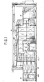
- FIG. 1 represents a perspective view of an intervention workshop designated by the reference generate 1. It is made up of assembled panels which constitute both the vertical walls and the horizontal ceiling 6 of L'ateLier. These panels are standard panels such as Panel 2 or frame panels such as panel 4 which has a central opening 4a which makes it possible to attach plexiglass or metal plates to equipment such as a viewing window, rounds of glove 5, passages necessary for connection of ventilation 7, utility passages, the docking flange of a container, for example such as that described in document FR-A-2418 527.
- the edges of the panels are folded twice at right angles and welded in The angles.
- the structure of the panels is reinforced by a diamond point folding 10 made with the sheet bending machine.
- the wings 8a and 8b of the U-shaped profile have fixing holes referenced respectively 9a and 9b.
- the holes 9b of the border 8b allow the panels to be fixed together so that their surfaces located inside the enclosure are at the same level. This facilitates decontamination operations during and at the end of operation, because the interior faces of the panels are as smooth as possible without grainy coating or sharp corners.
- the wings 8a of the panels have holes 11 which allow them to be fixed to an external stiffening system (see FIG. 4).
- the holes in the border 8b also allow the fixing of the panels to the floor, to the vertical walls and to the ceiling. It is made up of connecting elements and corner pieces.
- the edge of the panels also allows the installation of seals.
- the panels are rectangular or square.
- the standard panel measures 0.80 m x 1.60 m but there are also panels of 0.40 m x 1.60 m, 0.80 m x 0.80 m and 0.40 x 0.80 m.
- connection of two perpendicularly mounted panels is carried out by means of corner pieces ( Figures 8 and 10).
- the corner piece is bolted to each panel. It is made up of a L-shaped sheet. Its Length is a multiple or a sub-multiple of The length of a module.
- the panels can also be connected by a corner piece with four or five faces in ptied and welded head ( Figures 5 to 8 and 10).
- the frame panels make it possible to adapt a large number of equipment.
- a waterproof single leaf door is mounted on a frame that can be adapted in place of two or more standard panels. The whole is called panel-worn.
- One of these doors is equipped with an anti-panic opening system, that is to say a door comprising a large handle and opening from the inside to the outside.
- We can also adapt to the frame panels a door or a hatch used for the entry of the material to be dismantled.
- the doors or the hatches for the equipment are single-leaf sealed. They are mounted in 1.6 x 2.4 m frames.
- the waste from the dismantling workshop is evacuated by an airlock which allows waterproof docking by plating a 200-liter petroleum drum on the waste evacuation system or by placing it on a flange panel. docking described in Patent FR-A-2 418 527.
- the gloves which equip the lateral faces of the airlock make it possible to fill the barrel, crimping the cover and helping to position the barrel, Installing or removing the cover.
- the ventilation keeps the airlock in dynamic tightness.
- the maneuvering box of the cover acts as a transfer duct for the outside air to the intervention workshop to avoid contamination of the mechanics of the waste evacuation system.
- the airlock can also be equipped with a bag round of 1000 mm in diameter which allows the exit of large-scale waste under welded vinyl.
- seals The watertightness of the modular panels between they are made using seals.
- These seals can be plastic seals with silicones such as Gebsicon or Le Robson transtucide.
- Said first wings 8b of the panels are assembled together in a leaktight manner by a flexible, non-flammable plastic silicone seal.
- Each of said first wings 8b is coated with each of the panels to be assembled with silicone.
- These wings are assembled by bolting. We remove the excess seal that smeared when tightening the two panels. A certain amount of seal is added along the edge of the two panels located inside the confinement enclosure, then a protective adhesive strip is placed over it. After assembly of the workshop, an adhesive strip is stuck on the angles of the modular cell.
- This strip facilitates the decontamination of workshops by smear or spraying with dilute nitric acid or conventional detergents.
- the sealing between the frames and the panels of these frames is achieved by means of O-rings.
- the edges of the panels are bolted to a connecting element overlapped in the ground, vertical walls or ceilings.
- the connecting element 9 is fixed to a civil engineering structure 14 by a dowel 16.
- the diameters of the bolts and dowels are identical to facilitate mounting.
- the connecting elements 9 constituted by metal belts make it possible to make up for the faults of civil engineering, that is to say floors, ceilings and walls.
- the installation of these elements must be done before mounting the panels. They consist of a sheet of stainless steel folded twice at right angles.
- One of the branches is placed on the ground.
- the other branch supports the panel ( Figure 4).
- Their Length is a submultiple or a multiple of the length of a standard panel.
- the panels can, if necessary, be maintained by a frame.
- This frame is then built outside the workshop and can be adapted to its dimensions. It will be made up, for example, of profiles or lattice girders.
- the connecting elements at right angles to the sectional panels shown in Figure 5 allow the dimensions of the workshop to be extended.
- One element has folded U-shaped edges, the wings 18a, 18b of which are provided with fixing holes 19b, allowing them to be fixed to the panels and possibly holes 19a allowing them to be fixed to an external stiffening system.
- the posts or the beams are fixed on the civil engineering, like the belts, by means of dowels and buttoned on the folded side of the panels. They optionally serve to fix the biological protections 20 shown in FIG. 9.
- An intervention workshop carried out using modular panels of the invention has many advantages.
- the self-supporting structure of the workshop and the modularity of all of its metal panels and accessories allow one or more elements to be exchanged with one or more others both during assembly. and during operation only after decontamination of the workshop to modify its initial architecture.
- Plexiglas or metal panels can be tightly fixed, for example using clamps, on a frame adapted to allow vision, assistance to operators by glove rings, the exit of small materials under vinyl or trash cans DTPE La Calhène, The connection of air transfer or extraction circuits of Ventilation, Connections of service fluids and electrical circuits, connections of electrical safety systems such as Detection systems and safety fluid distribution circuits such as fire extinguishing, breathing air, emergency lighting, etc.
- An important advantage of the invention lies in the fact that the design of the panels with structure turned towards the outside makes it possible to have an internal surface free of any structure capable of becoming a place of retention and discomfort for decontamination.
- the dismantling workshop is made of stainless steel to avoid corrosion of the panels, but it can be done in any other metal or material in particular in self-extinguishing composite materials.
- roof hatches of identical design to that of the doors which allow the evacuation of heavy parts or of large dimensions such as the biological protections of the ⁇ - ⁇ armored cells. made up of cast iron or lead plates, Workshop machines, etc ...
- FIG. 6 There are shown in Figures 6 and 7 two embodiments of a connecting element for connecting three walls in a scalable structure according to the invention.
- Element 40 (FIG. 6) has four walls, namely two complete square walls and two other walls made up of squares of which a corner has been cut. Each of these faces is pierced with a hole which allows its fixing by bolting to the second wings 8a of the panels.
- connection element 42 (FIG. 7) consists of a cube from which one of the faces has been removed. It thus has five square walls each having a hole which allows it to be bolted to the second wings 8a of the panels.
- Figure 5 a partial view of a structure according to the invention illustrating the connection of two walls formed by perpendicular panels.
- connection elements There is a connecting element 44. It is fixed by bolting its first wings 18b to panels, 2 the representation of which has only been started in FIG. 5. The corner shown in FIG. 5 is therefore a re-entrant corner.
- the folded sides of the edge of the panels allow to fix beams, posts or standard benefits adapted to biological protections, namely seasoned lead bricks, borated concrete bricks, more or less thick concrete slabs, boxes filled with lead shot, etc.
- neutral protective means such as paraffin bricks or boxes filled with water, in the case of risk criticality excursion.
- FIG. 9 shows the means which allow the attachment of a biological protection wall to the external wall of a structure according to the invention.
- These means consist of sections 52 in I. Two of the wings of these sections are used to fix them by bolting to the first wings 8b of the panels 2 forming a wall of the structure, as shown diagrammatically by the dashed lines 54.
- the wings of the sections 52 serve as guide rails and support of the bioLogical protective wall 20.
- This wall consists of a stack of lead bricks. It could also consist of plates or boxes. It is placed parallel to the panels 2 or 4, and arranged between the sections 52.
- Profits such as Profits 52 could also be used to improve the rigidity of the structure without a biological protection wall being arranged parallel to the panels. Instead of the profiles, one could also use posts or beams to improve the rigidity of the structure, the latter being bolted to the second wings 8a of the panels.
- FIG. 10 shows a view of below your junction between three panels 2. This junction is obtained by angles 46 buttoned to the first wings 8a of the panels. Two outgoing angles 58 are thus made.
- the exterior and interior of the structure have been designated by the references 48 and 50 respectively. Note that in this case, the angles 46 are located outside of the structure.
- connection element consisting of a simple angle iron 46 comprising two faces with a right angle pierced with holes.
- This angle 46 is fastened by buttoning to a first wing 8b of the panels 2.
- first and second wings of the panels 2, as well as the first and second aisles of the connection element 46 are located towards the outside of The enclosure.
- the outside of this enclosure has been designated by the reference 48 and the area located inside by the reference 50.
- the corner shown in Figure 8 is therefore a re-entrant corner. It is therefore noted that the angle 46 is located inside the enclosure.
- a connecting element 40 as illustrated in FIG. 6, is overlaid at the junction between the connecting element 44 and the panel 2 fixed to the angle iron 46.
Abstract
Description
L'invention concerne une structure évoluable qui constitue une enceinte étanche. Elle s'applique notamment à La réalisation d'un atelier de démantèlement d'équipements nucléaires. Elle peut être utilisée également pour un stockage, ou en un milieu non hostile.The invention relates to a scalable structure which constitutes a sealed enclosure. It applies in particular to the realization of a nuclear equipment dismantling workshop. It can also be used for storage, or in a non-hostile environment.
Les opérations de démantèlement d'équipements nucléaires consistent en un démontage ou en un découpage de tuyauteries et d'appareils contaminés par des radionucléides. Dans Le but d'éviter une dissémi- tation de cette contamination, ces opérations sont réalisées dans une enceinte confinée appelée, atelier d'intervention, constituée autour des équipements à démanteler.The dismantling of nuclear equipment consists of dismantling or cutting pipes and equipment contaminated by radionuclides. In order to avoid the spread of this contamination, these operations are carried out in a confined enclosure called an intervention workshop, built around the equipment to be dismantled.
Selon La technique actuellement connue, on crée une barrière de confinement lors des opérations d'intervention en milieu contaminé au moyen d'une paroi souple supportée par des mâts métalliques ou une armature métallique constituée d'un assemblage de tubes ou encore une armature pneumatique de manière à réaliser une sorte de tente dont Les parois sont colLées et qui isole les équipements à démanteler.According to the currently known technique, a confinement barrier is created during intervention operations in a contaminated medium by means of a flexible wall supported by metal masts or a metal frame consisting of an assembly of tubes or even a pneumatic frame of so as to make a kind of tent whose walls are glued and which isolates the equipment to be dismantled.
Pour La construction des ateliers d'intervention, on utilise des feuilles de vinyle gonflables reliés entre eux par des fermetures à glissière ou des panneaux de plexiglas fixés par rivetage ou boulonnage sur une armature. L'étanchéité de ces enceintes sur Les structures du bâtiment est réalisée grâce au coLlage ou à La fixation par des bandes adhésives d'une bavette de toile de vinyle. Des fenêtres en vinyle cristal ou en plexiglas permettent La vision des opérations depuis l'exterieur ainsi que l'éclairage de L'intérieur.For the construction of the intervention workshops, we use inflatable vinyl sheets linked together by zippers or Plexiglas panels fixed by riveting or bolting on a frame. These enclosures are sealed on the building structures by gluing or fixing with adhesive strips a flap of vinyl canvas. Windows in crystal vinyl or plexiglass allow the vision of operations from the outside as well as the lighting of the interior.
De telles réalisations connues présentent un grand nombre d'inconvénients.Such known embodiments present a lot of drawbacks.
Le principal de ces inconvénients réside dans le fait qu'en cas d'incendie les parois de vinyle sont détruites et la fonction de confinement n'est plus assurée. De plus, Les mâts et les armatures métalliques ou pneumatiques présents à L'intérieur de L'atelier d'intervention forment des recoins qui sont des lieux de rétention de la contamination et gênent La décontamination.The main drawback is that in the event of a fire, the vinyl walls are destroyed and the containment function is no longer ensured. In addition, the metal or pneumatic masts and frames present inside the intervention workshop form recesses which are places of retention of contamination and hinder decontamination.
En outre, Les enceintes connues ne permettent pas d'interchanger un ou plusieurs éléments pendant Le montage et après décontamination de l'atelier, ou même en cours d'exploitation, pour modifier L'architecture initiale.In addition, the known enclosures do not allow one or more elements to be interchanged during assembly and after decontamination of the workshop, or even during operation, to modify the initial architecture.
Dans le cas où les équipements nucléaires comportent en plus un risque d'irradiation (ateliers d'intervention β-γ), les ateliers d'intervention connus ne comportent pas de protection biologique.In the case where the nuclear equipment additionally involves a risk of irradiation (intervention workshops β-γ), the known intervention workshops do not include biological protection.
On connaît également (GB-A-791706 (RENARI)) un panneau de forme carrée ou rectangulaire présentant une périphérie conformée de manière à permettre l'assemblage de plusieurs panneaux similaires, de manière à former des structures variées. Chacun des côtés du panneau comporte un rebord rectangulaire perpendiculaire au plan du panneau. Le bord du panneau comporte des trous qui permettent leur fixation. Des éléments de raccordement triangulaires ou longitudinaux ou à profits en U sont prévus. Cependant, La bordure du panneau est interrompue. Ce panneau n'est donc pas susceptible de constituer une enceinte de confinement. De plus, le problème de L'étanchéité entre Les panneaux n'a pas été envisagé.Also known (GB-A-791706 (RENARI)) is a square or rectangular panel having a shaped periphery so as to allow the assembly of several similar panels, so as to form various structures. Each side of the panel has a rectangular flange perpendicular to the plane of the panel. The edge of the panel has holes that allow them to be fixed. Triangular or longitudinal or U-shaped connecting elements are provided. However, the border of the panel is interrupted. This panel is therefore not likely to constitute a confinement enclosure. In addition, the problem of sealing between the panels has not been considered.
On connaît également (FR-A-2201375 (NURMI-NEN)) un panneau modulaire permettant de constituer une cloison. IL est constitué d'une feuille d'acier recouverte d'une couche de matière plastique dont Les bords longitudinaux sont repliés deux fois à 90° afin de constituer un rebord à profil en U. Les panneaux sont assemblés en chauffant le revêtement en matière plastique de façon à Le faire fondre. Cependant, le profil de La bordure de ces panneaux n'est pas continu de sorte qu'ils ne conviennent pas pour réaliser une enceinte de confinement étanche. De plus, La Liaison entre deux panneaux n'est pas démontable, de telle sorte qu'ils ne permettent pas de réaliser une structure évoluable.There is also known (FR-A-2201375 (NURMI-NEN)) a modular panel making it possible to constitute a partition. IT consists of a steel sheet covered with a layer of plastic material, the longitudinal edges of which are folded twice at 90 ° to form a rim with a U-profile. The panels are assembled by heating the plastic coating so as to melt it. However, the profile of the border of these panels is not continuous so that they are not suitable for producing a sealed containment enclosure. In addition, the connection between two panels is not removable, so that they do not allow for a scalable structure.
La présente invention a précisément pour but de remédier à ces inconvénients de L'art antérieur en créant une structure modulaire évoluable de confinement composée de panneaux. Les panneaux doivent être démontables de manière qu'un panneau d'un type donné puisse être remplacé par un panneau d'un autre type, ou que L'on puisse faire varier à volonté Les dimensions de La structure en ajoutant des panneaux supplémentaires ou en en retirant. En outre, La structure doit permettre de constituer une enceinte parfaitement étanche, notamment pour l'application à La création d'une barrière de confinement d'équipements nucléaires à démanteler.The object of the present invention is precisely to remedy these drawbacks of the prior art by creating a modular modular structure of containment composed of panels. The panels must be removable so that a panel of a given type can be replaced by a panel of another type, or so that the dimensions of the structure can be varied at will by adding additional panels or by removing. In addition, the structure must make it possible to constitute a perfectly sealed enclosure, in particular for the application to the creation of a containment barrier for nuclear equipment to be dismantled.
Ces buts sont atteints,conformément à L'invention par La création d'une structure modulaire évoluable de confinement composée de panneaux rectangulaires ou carrés, présentant une face, et en périphérie de cette face, une bordure rabattue constituée par une première aile rabattue à angle droit par rapport à La face du panneau, et une seconde aile rabattue à angle droit par rapport à La première aile, lesdites première et seconde ailes constituant une bordure en U par LaqueLLe Lesdits panneaux sont assemblés par boulonnage, et des éléments de raccordement pour assembler deux ou trois desdits panneaux et des éléments entre deux, trois ou quatre desdits panneaux, caractérisée en ce que :
- - La bordure en U des panneaux est continue sur toute La périphérie de La face d'un panneau ;
- - lesdits panneaux étant assemblés entre eux et aux- dits éléments de raccordement par Lesdites premières asles, les premières et secondes ailes étant disposées vers L'extérieur de La structure, Les faces des panneaux étant de niveau de manière à constituer des parois internes parfaitement planes ;
- - Lesdits éléments du raidissement étant assemblés auxdits panneaux par Lesdites secondes ailes ;
- - un joint étant inséré entre Lesdites premières ailes, ce joint étant amovible de manière à préserver La démontabitité des panneaux.
- - The U-shaped border of the panels is continuous over the entire periphery of the face of a panel;
- - Said panels being assembled together and said connecting elements by said first asles, the first and second wings being arranged towards the outside of the structure, the faces of the panels being level so as to constitute perfectly flat internal walls ;
- - Said stiffening elements being assembled to said panels by said second wings;
- - A seal being inserted between said first wings, this seal being removable so as to preserve the dismantling of the panels.
Gràce à cette structure, chaque panneau peut être aisément démonté et remplacé par un panneau d'un autre type. Une étanchéité est assurée entre Les panneaux grâce à la présence desdites premières ailes et à la présence d'un joint d'étanchéité souple pLastique et ininflammable. L'étanchéité reste assurée même en cas d'incendie.Thanks to this structure, each panel can be easily dismantled and replaced by a panel of another type. A seal is ensured between the panels thanks to the presence of said first wings and to the presence of a flexible plastic and non-flammable seal. Sealing remains assured even in the event of fire.
En outre, étant donné que Les faces intérieures des panneaux sont lisses, Les parois constituées par L'assembLage de plusieurs panneaux adjacents sont de niveau. IL en résulte une absence de recoins dans lesquels les poussières contaminées pourraient s'accumuler. La décontamination est ainsi facilitée.In addition, since the interior faces of the panels are smooth, the walls formed by the assembly of several adjacent panels are level. This results in an absence of corners in which the contaminated dust could accumulate. Decontamination is thus facilitated.
De préférence, certains desdits panneaux, dits panneaux-cadres, présentent une ouverture centrale, une plaque en plexiglas ou en métal étant fixée sur L'ouverture par boulonnage sur La face du panneau 4, un joint d'étanchéité étant interposé entre La face et ladite plaque de fermeture, cette plaque supportant un équipement tel qu'un hublot de vision, des ronds de gants, des passages de fluide, un télémanipulateur, une bride d'accostage de conteneur.Preferably, some of said panels, called frame panels, have a central opening, a plexiglass or metal plate being fixed to the opening by bolting on the face of the
De préférence, lesdites secondes ailes sont boulonnées à des poteaux, des poutres, des plaques hexagonales ou des profités en T pour améliorer La rigidité de ladite structure.Preferably, said second wings are bolted to posts, beams, hexagonal plates or T-shaped sections to improve the rigidity of said structure.
De préférence également, des profiLés en I sont fixés verticalement sur Les secondes ailes des bords rabattus et une protection biotogique constituée par un empilement de briques, de plaques ou de caissons, est placée parallèlement aux panneaux et entre Les profilés en I.Also preferably, I-shaped profiles are fixed vertically on the second wings of the folded edges and a biotogic protection consisting of a stack of bricks, plates or boxes, is placed parallel to the panels and between the I-sections.
De préférence, lesdits éléments de raccordement comportent :
- - des pièces d'angle en forme de profilés en équerre pour raccorder deux desdits panneaux à angle droit tournés vers L'extérieur de la structure ;
- - des pièces d'angle en forme de profilés en équerre avec bordure en U rabattue vers L'intérieur pour raccorder deux panneaux à angle droit tournés vers L'intérieur de La structure ;
- - des pièces d'angle en forme de parallèlépipèdes ouverts à quatre ou cinq faces, des profités en U améliorant L'adaptation de Ladite structure au génie civil.
- - corner pieces in the form of angle profiles for connecting two of said panels at right angles facing towards the outside of the structure;
- - corner pieces in the form of angled profiles with U-shaped edge folded inwards to connect two panels at right angles facing the interior of the structure;
- - corner pieces in the form of parallelepipeds open to four or five faces, U-shaped benefits improving the adaptation of said structure to civil engineering.
L'invention est exposée plus en détail à L'aide de dessins représentant seulement un mode d'exécution.
- La figure 1 est une vue en perspective d'un atelier d'intervention réalisé au moyen de panneaux modulaires conformément à L'invention.
- La figure 2 est une vue en plan d'un panneau modulaire conforme à L'invention.
- La figure 3 est une vue en coupe selon La ligne III-III de ta figure 2 d'un panneau modulaire de L'invention comportant une bride et Le système d'obturation d'un conteneur à déchets.
- La figure 4 est une vue en perspective qui montre La fixation à un étément de raccordement d'un panneau modutaire.
- La figure 5 est une vue en coupe d'un étément de raccordement des panneaux.
- Les figures 6 et 7 sont des vues en perspective de deux modes de réalisation d'un élément de raccordement utilisé pour raccorder trois parois d'une structure conforme à L'invention.
- La figure 8 est une vue partielle d'une structure conforme à L'invention illustrant Le raccordement de trois parois deux à deux perpendicutaires.
- La figure 9 illustre La fixation d'une protection biologique à L'intérieur d'une enceinte formée par une structure conforme à l'invention.
- La figure 10 est une vue de dessous illustrant un autre mode de raccordement de panneaux modutaires dans une structure conforme à L'invention.
- FIG. 1 is a perspective view of an intervention workshop produced by means of modular panels in accordance with the invention.
- Figure 2 is a plan view of a modular panel according to the invention.
- Figure 3 is a sectional view along La line III-III of FIG. 2 of a modular panel of the invention comprising a flange and the closure system of a waste container.
- Figure 4 is a perspective view which shows the attachment to a connecting element of a modular panel.
- Figure 5 is a sectional view of a panel connection element.
- Figures 6 and 7 are perspective views of two embodiments of a connecting element used to connect three walls of a structure according to the invention.
- Figure 8 is a partial view of a structure according to the invention illustrating the connection of three walls two by two perpendicular.
- FIG. 9 illustrates the attachment of biological protection inside an enclosure formed by a structure according to the invention.
- FIG. 10 is a view from below illustrating another method of connecting modular panels in a structure according to the invention.
La figure 1 représente une vue en perspective d'un atetier d'intervention désigné par La référence générate 1. IL est constitué de panneaux assemblés qui constituent aussi bien les parois verticales que Le plafond horizontal 6 de L'ateLier. Ces panneaux sont des panneaux standard tels que Le panneau 2 ou des panneaux cadres comme le panneau 4 qui comporte une ouverture centrale 4a qui permet de fixer des plaques en plexiglas ou en métal à un équipement tel qu'un hublot de vision, des ronds de gant 5, des passages nécessaires au raccordement de La ventilation 7, des passages d'utilité, La bride d'accostage d'un conteneur, par exempte teLLe que cette qui est décrite dans le document FR-A-2418 527.FIG. 1 represents a perspective view of an intervention workshop designated by the reference generate 1. It is made up of assembled panels which constitute both the vertical walls and the horizontal ceiling 6 of L'ateLier. These panels are standard panels such as
Les bordures des panneaux standards et celles des panneaux cadres sont identiques. Elles sont constituées par un profil en U (voir figure 3).The borders of the standard panels and those of the frame panels are identical. They consist of a U-shaped profile (see Figure 3).
Les bords des panneaux sont pliés deux fois à angle droit et soudés dans Les angles. La structure des panneaux est renforcée par un pliage en pointe de diamant 10 réalisé à la plieuse à tôles.The edges of the panels are folded twice at right angles and welded in The angles. The structure of the panels is reinforced by a diamond point folding 10 made with the sheet bending machine.
Les ailes 8a et 8b du profil en U comportent des trous de fixation référencés respectivement 9a et 9b. Les trous 9b de La bordure 8b permettent La fixation des panneaux entre eux de manière que leurs surfaces situées à L'intérieur de L'enceinte soient au même niveau. Ceci facilite Les opérations de décontamination en cours et en fin d'exploitation, car Les faces intérieures des panneaux sont aussi lisses que possible sans revêtement granuleux ni angles vifs.The
Les ailes 8a des panneaux comportent des trous 11 qui permettent leur fixation éventueLLe à un système extérieur de raidissement (voir figure 4). Les trous de La bordure 8b permettent également La fixation des panneaux au sol, sur Les murs verticaux et au plafond. Elle est réalisée par des éléments de raccordement et des pièces d'angle. La bordure des panneaux permet également la pose de joints d'étanchéité.The
Les panneaux sont rectangulaires ou carrés. Le panneau type mesure 0,80 m x 1,60 m mais il existe également des panneaux de 0,40 m x 1,60 m de 0,80 m x 0,80 m et de 0,40 x 0,80 m.The panels are rectangular or square. The standard panel measures 0.80 m x 1.60 m but there are also panels of 0.40 m x 1.60 m, 0.80 m x 0.80 m and 0.40 x 0.80 m.
Le raccordement de deux panneaux montés per- pendicutairement est réàlisé au moyen de pièces d'angle (figure 8 et 10). La pièce d'angle est boulonnée à chaque panneau. Elle est constituée par une tôle ptiée en L. Sa Longueur est un multiple ou un sous-multiple de La longueur d'un module. Les panneaux peuvent également être raccordés par une pièce d'angle à quatre ou cinq faces en tôte ptiée et soudée (figure 5 à 8 et 10).The connection of two perpendicularly mounted panels is carried out by means of corner pieces (Figures 8 and 10). The corner piece is bolted to each panel. It is made up of a L-shaped sheet. Its Length is a multiple or a sub-multiple of The length of a module. The panels can also be connected by a corner piece with four or five faces in ptied and welded head (Figures 5 to 8 and 10).
Les panneaux cadres permettent d'adapter un grand nombre d'équipements. Une porte à simple battant étanche est montée sur un cadre adaptable à La place de deux ou plusieurs panneaux standards. L'ensembLe est appelé panneau-porté. Une de ces portesest équipée d'un système d'ouverture anti-panique, c'est-à-dire une porte comportant une poignée de grande dimension et s'ouvrant de L'intérieur vers L'extérieur. On peut adapter également aux panneaux cadres une porte- sas ou une trappe utilisée pour l'entrée du matériel à démanteler. Les portes ou Les trappes pour le matériel sont à simple battant étanche. Elles sont montées dans des cadres de 1,6 x 2,4 m.The frame panels make it possible to adapt a large number of equipment. A waterproof single leaf door is mounted on a frame that can be adapted in place of two or more standard panels. The whole is called panel-worn. One of these doors is equipped with an anti-panic opening system, that is to say a door comprising a large handle and opening from the inside to the outside. We can also adapt to the frame panels a door or a hatch used for the entry of the material to be dismantled. The doors or the hatches for the equipment are single-leaf sealed. They are mounted in 1.6 x 2.4 m frames.
Les déchets de L'atelier de démantèlement sont évacués par un sas qui permet L'accostage étanche par placage d'un fût pétrolier de 200 litres sur Le système d'évacuation de déchets ou grâce à La mise en place sur un panneau de La bride d'accostage décrite dans Le brevet FR-A-2 418 527. Les gants qui équipent Les faces latérates du sas permettent d'effectuer le remplissage du fût, Le sertissage du couvercle et d'aider à La mise en position du fût, à La pose ou à La dépose du couvercle.The waste from the dismantling workshop is evacuated by an airlock which allows waterproof docking by plating a 200-liter petroleum drum on the waste evacuation system or by placing it on a flange panel. docking described in Patent FR-A-2 418 527. The gloves which equip the lateral faces of the airlock make it possible to fill the barrel, crimping the cover and helping to position the barrel, Installing or removing the cover.
La ventilation maintient le sas en étanchéité dynamique. De plus, Le caisson de manoeuvre de l'opercule sert de gaine de transfert de l'air extérieur vers l'atelier d'intervention pour éviter La contamination de la mécanique du système d'évacuation de déchets. Le sas peut également être équipé d'un rond de sac de 1000 mm de diamètre qui permet La sortie des déchets de grandes dimensions sous vinyle soudé.The ventilation keeps the airlock in dynamic tightness. In addition, the maneuvering box of the cover acts as a transfer duct for the outside air to the intervention workshop to avoid contamination of the mechanics of the waste evacuation system. The airlock can also be equipped with a bag round of 1000 mm in diameter which allows the exit of large-scale waste under welded vinyl.
L'étanchéité des panneaux modutaires entre eux est réalisée à l'aide de joints. Ces joints peuvent être des joints plastiques aux silicones tels que le Gebsicon ou Le Robson transtucide. Lesdites premières ailes 8b des panneaux sont assemblées entre elles de manière étanche par un joint au silicone souple plastique et ininflammable. On revêt chacune desdites premières ailes 8b de chacun des panneaux à assembler de silicone. On assemble ces ailes par bouLonnage. On retire L'excédent de joint qui a bavé lors du serrage des deux panneaux. On rajoute une certaine quantité de joint Le long de L'arête des deux panneaux située à L'intérieur de L'enceinte de confinement, puis on pose par dessus une bande adhésive de protection. Après montage de l'atelier, une bande adhésive est collée sur Les angles de La cellule modutaire. Cette bande facilite La décontamination des ateliers par frottis ou aspersion avec de L'acide nitrique dilué ou des détergents classiques. L'étanchéité entre Les cadres et Les panneaux de ces cadres est réalisée au moyen de joints toriques. Les bordures de panneaux sont boulonnées sur un étément de raccordement chevilté dans le sol, Les murs verticaux ou Les plafonds. Par exemple, sur la figure 4, L'éLément de raccordement 9 est fixé à une structure du génie civil 14 par une cheville 16. Les diamètres des boulons et des chevilles sont identiques pour faciliter Le montage. Les éléments de raccordement 9 constitués par des ceintures métalliques permettent de rattraper Les défauts du génie civil, c'est-à-dire des planchers, des plafonds et des murs. La mise en place de ces éléments doit être faite avant le montage des panneaux. Ils sont constitués par une tôle d'acier inoxydable pliée deux fois à angle droit. L'une des branches est placée sur Le sol. L'autre branche sert d'appui au panneau (figure 4). Leur Longueur est un sous-multiple ou un multiple de la longueur d'un panneau standard.The watertightness of the modular panels between they are made using seals. These seals can be plastic seals with silicones such as Gebsicon or Le Robson transtucide. Said
Bien que La structure de L'ateLier d'intervention soit autoporteuse, les panneaux peuvent, Le cas échéant, être maintenus par une charpente. Cette charpente est alors construite à L'extérieur de l'atelier et peut s'adapter à ses dimensions. Elle sera constituée par exempte par des profilés ou des poutres en treillis.Although the structure of the intervention workshop is self-supporting, the panels can, if necessary, be maintained by a frame. This frame is then built outside the workshop and can be adapted to its dimensions. It will be made up, for example, of profiles or lattice girders.
Les éléments de raccordement en équerre des panneaux en section représentés sur La figure 5 permettent L'extension des dimensions de L'atelier. Il existe des éléments en équerre pour Les panneaux standards, Les ceintures et Les pièces d'angle. Un élément comporte des bordures repliées en U, dont Les ailes 18a, 18b, sont munies de trous de fixation 19b, permettant Leur fixation aux panneaux et éventuellement de trous 19a permettant Leur fixation à un système de raidissement extérieur.The connecting elements at right angles to the sectional panels shown in Figure 5 allow the dimensions of the workshop to be extended. There are square elements for standard panels, belts and corner pieces. One element has folded U-shaped edges, the
Les poteaux ou Les poutres sont fixés sur Le génie civil, comme Les ceintures, par L'intermédiaire de chevilles et boutonnés sur Le côté rabattu des panneaux. Ils servent éventuellement à La fixation des protections biologiques 20 représentées sur La figure 9.The posts or the beams are fixed on the civil engineering, like the belts, by means of dowels and buttoned on the folded side of the panels. They optionally serve to fix the
Pour favoriser La tenue des panneaux entre eux, il est possible d'envisager des pièces de raccordement entre Les angles communs de trois ou quatre panneaux voisins (figure 6 à 8).To promote the holding of the panels together, it is possible to envisage connecting pieces between the common angles of three or four neighboring panels (FIGS. 6 to 8).
Un atelier d'intervention réalisé au moyen de panneaux modulaires de L'invention présente de nombreux avantages.An intervention workshop carried out using modular panels of the invention has many advantages.
La structure autoporteuse de l'atelier et La modularité de L'ensemble de ses panneaux métalliques et accessoires permettent d'échanger un ou plusieurs éléments avec un ou plusieurs autres tant au montage et en cours d'exploitation qu'après décontamination de l'atelier pour modifier son architecture initiale.The self-supporting structure of the workshop and the modularity of all of its metal panels and accessories allow one or more elements to be exchanged with one or more others both during assembly. and during operation only after decontamination of the workshop to modify its initial architecture.
Elle permet une grande possibilité d'adaptation pour La réalisation des ateliers d'intervention. Ces derniers sont entièrement structurés. Cette structure est autoporteuse. En cas d'incendie, elle garde ses fonctions de confinement et son volume. On peut fixer de manière étanche, par exemple à L'aide de serre-joints, des panneaux de plexiglas ou de métal sur un cadre adapté pour permettre La vision, l'aide aux opérateurs par des ronds de gant, La sortie de petits matériels sous manches de vinyle ou de poubelle DTPE La Calhène, Le raccordement des circuits de transfert ou d'extraction de l'air de La ventilation, des Liaisons des fluides de service et des circuits électriques, des liaisons des systèmes électriques de sûreté comme La détection d'incendie et des circuits de distribution de fluide de sécurité comme l'extinction d'incendie, l'air respiratoire, l'éclairage de secours...It allows a great possibility of adaptation for the realization of intervention workshops. These are fully structured. This structure is self-supporting. In the event of a fire, it retains its containment functions and its volume. Plexiglas or metal panels can be tightly fixed, for example using clamps, on a frame adapted to allow vision, assistance to operators by glove rings, the exit of small materials under vinyl or trash cans DTPE La Calhène, The connection of air transfer or extraction circuits of Ventilation, Connections of service fluids and electrical circuits, connections of electrical safety systems such as Detection systems and safety fluid distribution circuits such as fire extinguishing, breathing air, emergency lighting, etc.
Un avantage important de L'invention réside dans Le fait que La conception des panneaux à structure retournée vers L'extérieur permet d'avoir une surface interne exempte de toute structure susceptible de devenir un Lieu de rétention et de gêne pour La décontamination.An important advantage of the invention lies in the fact that the design of the panels with structure turned towards the outside makes it possible to have an internal surface free of any structure capable of becoming a place of retention and discomfort for decontamination.
L'utilisation d'un joint plastique au silicone tel que Le Gebsicon fabriqué et commercialisé par La Société Rhône-Poulenc, Le Rubson translucide, permet, Lors du démontage, d'avoir une surface immédiatement réutilisable sans problème d'entretien des joints.The use of a silicone plastic seal such as Le Gebsicon manufactured and marketed by La Société Rhône-Poulenc, Le Rubson translucide, makes it possible, during disassembly, to have an immediately reusable surface without problem of joint maintenance.
De préférence, l'atelier de démantèlement est réalisé en acier inoxydable afin d'éviter La corrosion des panneaux mais il peut être réalisé en tout autre métal ou matériau en particutier en matériaux composites auto-extinguibtes.Preferably, the dismantling workshop is made of stainless steel to avoid corrosion of the panels, but it can be done in any other metal or material in particular in self-extinguishing composite materials.
On peut adapter, sur l'atelier d'intervention de l'invention, des trappes de toit de conception identique à cette des portes qui permettent L'évacuation de pièces Lourdes ou de grandes dimensions telles que Les protections biologiques des cellules blindées β-γ constituées par des plaques de fonte ou de plomb, Les machines de l'atelier, etc...It is possible to adapt, on the intervention workshop of the invention, roof hatches of identical design to that of the doors which allow the evacuation of heavy parts or of large dimensions such as the biological protections of the β-γ armored cells. made up of cast iron or lead plates, Workshop machines, etc ...
On a représenté sur Les figures 6 et 7 deux modes de réalisation d'un éLément de raccordement destiné à raccorder trois parois dans une structure évoluable conforme à L'invention. L'éLément 40 (figure 6) comporte quatre parois, à savoir deux parois carrées complètes et deux autres parois constituées par des carrés dont-on a coupé un coin. Chacune de ces faces est percée d'un trou qui permet sa fixation par boulonnage aux secondes ailes 8a des panneaux.There are shown in Figures 6 and 7 two embodiments of a connecting element for connecting three walls in a scalable structure according to the invention. Element 40 (FIG. 6) has four walls, namely two complete square walls and two other walls made up of squares of which a corner has been cut. Each of these faces is pierced with a hole which allows its fixing by bolting to the
L'étément de raccordement 42 (figure 7) est constitué par un cube dont on a ôté une des faces. IL comporte ainsi cinq parois carrées présentant chacune un trou qui permet sa fixation par boulonnage aux secondes ailes 8a des panneaux.The connection element 42 (FIG. 7) consists of a cube from which one of the faces has been removed. It thus has five square walls each having a hole which allows it to be bolted to the
On a représenté sur La figure 5 une vue partielle d'une structure conforme à L'invention illustrant le raccordement de deux parois constituées par des panneaux perpendicutaires. PLusieurs types d'étéments de raccordement sont utilisés. On trouve un étément de raccordement 44. Il est fixé par boulonnage de ses premières ailes 18b à des panneaux, 2 dont La représentation a été seulement amorcée sur La figure 5. Le coin représenté sur La figure 5 est donc un coin rentrant.There is shown in Figure 5 a partial view of a structure according to the invention illustrating the connection of two walls formed by perpendicular panels. Several types of connection elements are used. There is a connecting
Dans le cas de L'utiLisation de L'ateLier d'intervention pour réaliser une enceinte où se déroulent des travaux qui impliquent un risque d'irradiation, Les côtés rabattus du bord des panneaux permettent de fixer des poutres, des poteaux ou des profités standard adaptés aux protections biologiques, à savoir des briques de plomb chevronnées, des briques de béton borité, des plaques de béton plus ou moins épaisses, des caissons remplis de grenaille de plomb, etc... On peut également utiliser des moyens de protection neu- trophages, comme des briques de paraffine ou des caissons remplis d'eau, dans Le cas de risque d'excursion de criticité.In the case of using the intervention workshop to create an enclosure where slow work which involves a risk of irradiation, The folded sides of the edge of the panels allow to fix beams, posts or standard benefits adapted to biological protections, namely seasoned lead bricks, borated concrete bricks, more or less thick concrete slabs, boxes filled with lead shot, etc. We can also use neutral protective means, such as paraffin bricks or boxes filled with water, in the case of risk criticality excursion.
On a représenté sur La figure 9, Les moyens qui permettent La fixation d'une paroi de protection biologique à La paroi extérieure d'une structure conforme à L'invention. Ces moyens sont constitués par des profilés 52 en I. Deux des ailes de ces profilés sont utilisées pour Les fixer par boulonnage aux premières ailes 8b des panneaux 2 formant une paroi de La structure, comme schématisé par Les traits mixtes 54. Les ailes des profilés 52 servent de glissières de guidage et de.maintien de La paroi de protection bioLogique 20. Cette paroi est constituée par un empilement de briques de plomb. Elle pourrait également être constituée de plaques ou de caissons. Elle est placée parallèlement aux panneaux 2 ou 4, et disposée entre Les profilés 52.FIG. 9 shows the means which allow the attachment of a biological protection wall to the external wall of a structure according to the invention. These means consist of
Des profités tels que Les profités 52 pourraient également être utilisés pour améliorer La rigidité de La structure sans qu'une paroi de protection biologique soit disposée parallèlement aux panneaux. A La place des profilés, on pourrait également utiliser des poteaux ou des poutres pour améliorer La rigidité de La structure, ces derniers étant boulonnés aux secondes ailes 8a des panneaux.Profits such as
On a représenté sur La figure 10 une vue de dessous de ta jonction entre trois panneaux 2. Cette jonction est obtenue par des cornières 46 boutonnées aux premières ailes 8a des panneaux. On réatise ainsi deux angles sortis 58. On a désigné respectivement par les références 48 et 50 L'extérieur et L'intérieur de la structure. On remarque que dans ce cas, Les cornières 46 se trouvent à l'extérieur de La structure.FIG. 10 shows a view of below your junction between three
On y trouve un premier type d'étément de raccordement constitué par une simple cornière 46 comportant deux faces à angte droit percées de trous. Cette cornière 46 est fixée par boutonnage à une première aile 8b des panneaux 2. On remarque que Les premières et secondes ailes des panneaux 2, ainsi que Les premières et secondes aites de l'étément de raccordement 46, sont situées vers L'extérieur de L'enceinte. On a désigné par la référence 48 L'extérieur de cette enceinte et par la référence 50 la zone située à L'intérieur. Le coin représenté sur La figure 8 est donc un coin rentrant. On remarque par conséquent que La cornière 46 se trouve à L'intérieur de L'enceinte. Enfin, on tropve un élément de raccordement 40, tel qu'illustré sur la figure 6, à La jonction entre l'élément de raccordement 44 et Le panneau 2 fixé à La cornière 46. On aurait pu égatement utiliser un étément de raccordement 42 de La figure 7.There is a first type of connection element consisting of a
Claims (8)
Applications Claiming Priority (2)
| Application Number | Priority Date | Filing Date | Title |
|---|---|---|---|
| FR8404458 | 1984-03-22 | ||
| FR8404458A FR2561692B1 (en) | 1984-03-22 | 1984-03-22 | MODULAR PANEL AND DISMANTLING WORKSHOP CONSTITUTED BY ASSEMBLING THESE PANELS |
Publications (2)
| Publication Number | Publication Date |
|---|---|
| EP0161133A1 true EP0161133A1 (en) | 1985-11-13 |
| EP0161133B1 EP0161133B1 (en) | 1988-12-07 |
Family
ID=9302341
Family Applications (1)
| Application Number | Title | Priority Date | Filing Date |
|---|---|---|---|
| EP19850400540 Expired EP0161133B1 (en) | 1984-03-22 | 1985-03-21 | Modulary evolvable structure for a partition |
Country Status (3)
| Country | Link |
|---|---|
| EP (1) | EP0161133B1 (en) |
| DE (1) | DE3566694D1 (en) |
| FR (1) | FR2561692B1 (en) |
Cited By (6)
| Publication number | Priority date | Publication date | Assignee | Title |
|---|---|---|---|---|
| FR2668789A1 (en) * | 1990-11-05 | 1992-05-07 | Accm Sarl | Modular system of panels permitting the containment of work areas and the isolation of humans from harmful environments |
| FR2724192A1 (en) * | 1994-09-07 | 1996-03-08 | Cogema | MODULAR CONTAINMENT ASSEMBLY DELIMITING A CONCLUDING VOLUME |
| GB2310224A (en) * | 1996-02-15 | 1997-08-20 | Shapland & Petter Ltd | Partition |
| EP0957324A1 (en) * | 1998-05-15 | 1999-11-17 | WSAB Virkestorkar AB | A module element for building up a self-supporting inner wall of a composite outer wall of a drying kiln for wooden material |
| EP0867674A3 (en) * | 1997-03-26 | 2000-09-06 | Robert Thomas Metall- und Elektrowerke | Drying chamber or tunnel and pre-heater for ceramic green shaped bodies |
| WO2012025453A1 (en) | 2010-08-22 | 2012-03-01 | Sperian Protection Clothing | Confinement airlock |
Citations (3)
| Publication number | Priority date | Publication date | Assignee | Title |
|---|---|---|---|---|
| GB791706A (en) * | 1954-10-23 | 1958-03-12 | Gabriel Renard | Panels for use as constructional units and the structures formed therefrom |
| FR2109017A7 (en) * | 1970-10-30 | 1972-05-26 | Tunzini Ameliorair Sa | |
| FR2140147A1 (en) * | 1971-06-04 | 1973-01-12 | Dinkel Anton |
-
1984
- 1984-03-22 FR FR8404458A patent/FR2561692B1/en not_active Expired
-
1985
- 1985-03-21 EP EP19850400540 patent/EP0161133B1/en not_active Expired
- 1985-03-21 DE DE8585400540T patent/DE3566694D1/en not_active Expired
Patent Citations (3)
| Publication number | Priority date | Publication date | Assignee | Title |
|---|---|---|---|---|
| GB791706A (en) * | 1954-10-23 | 1958-03-12 | Gabriel Renard | Panels for use as constructional units and the structures formed therefrom |
| FR2109017A7 (en) * | 1970-10-30 | 1972-05-26 | Tunzini Ameliorair Sa | |
| FR2140147A1 (en) * | 1971-06-04 | 1973-01-12 | Dinkel Anton |
Cited By (7)
| Publication number | Priority date | Publication date | Assignee | Title |
|---|---|---|---|---|
| FR2668789A1 (en) * | 1990-11-05 | 1992-05-07 | Accm Sarl | Modular system of panels permitting the containment of work areas and the isolation of humans from harmful environments |
| FR2724192A1 (en) * | 1994-09-07 | 1996-03-08 | Cogema | MODULAR CONTAINMENT ASSEMBLY DELIMITING A CONCLUDING VOLUME |
| EP0701032A1 (en) | 1994-09-07 | 1996-03-13 | Compagnie Generale Des Matieres Nucleaires | Modular confining assembly for the limitation of a closed, enlargeable volume |
| GB2310224A (en) * | 1996-02-15 | 1997-08-20 | Shapland & Petter Ltd | Partition |
| EP0867674A3 (en) * | 1997-03-26 | 2000-09-06 | Robert Thomas Metall- und Elektrowerke | Drying chamber or tunnel and pre-heater for ceramic green shaped bodies |
| EP0957324A1 (en) * | 1998-05-15 | 1999-11-17 | WSAB Virkestorkar AB | A module element for building up a self-supporting inner wall of a composite outer wall of a drying kiln for wooden material |
| WO2012025453A1 (en) | 2010-08-22 | 2012-03-01 | Sperian Protection Clothing | Confinement airlock |
Also Published As
| Publication number | Publication date |
|---|---|
| DE3566694D1 (en) | 1989-01-12 |
| FR2561692B1 (en) | 1986-11-14 |
| EP0161133B1 (en) | 1988-12-07 |
| FR2561692A1 (en) | 1985-09-27 |
Similar Documents
| Publication | Publication Date | Title |
|---|---|---|
| CA1206720A (en) | Building construction panel with partially embedded reinforcement in insulating material | |
| FR2476182A1 (en) | SANDWICH STRUCTURE PANEL ELEMENT FOR THE CONSTRUCTION, BY SIDE SIDE ASSEMBLY, OF WALLS | |
| EP0161133B1 (en) | Modulary evolvable structure for a partition | |
| EP1564337A1 (en) | Module for modular construction system | |
| EP0907587B1 (en) | Wall or casing made of metal sheets stretched over a frame or structure, and construction procedure | |
| CH615243A5 (en) | Window or French-window fittings | |
| KR101268334B1 (en) | Waterproofing structure for repairing of underwaterconstruction | |
| WO1998054418A1 (en) | Building framework | |
| FR2960578A1 (en) | Modular construction element for constructing portable temporary buildings i.e. shelters, has sealing joint extending between perpendicular surface and beveled junction surface, and framework comprising horizontal crosspieces | |
| FR2635801A1 (en) | Partitions manufactured by assembly of panels and glass panes | |
| EP0701032B1 (en) | Modular confining assembly for the limitation of a closed, enlargeable volume | |
| FR3011862A1 (en) | BUILDING MODULE | |
| EP2005011A1 (en) | Corner assembly comprising a male element preformed to a predetermined angle and bordered by returns | |
| EP0365512A1 (en) | Prefabricated construction units for building constructions, and construction process of buildings using these building units | |
| CH630433A5 (en) | Element intended for producing prefabricated structures | |
| FR3088080A1 (en) | CONTAINER OR BUNGALOW FOR STORING DANGEROUS PRODUCTS | |
| EP0133177A2 (en) | Prefabricated arched skylights with a transverse profile structure for fixing the same, and glazing with double peripheral sealings | |
| EP3553244B1 (en) | Construction element and construction comprising such an element | |
| EP0041044B1 (en) | Hexagonal structures | |
| FR2746130A1 (en) | Rapid assembly containment for high risk industrial plant | |
| WO1982004453A1 (en) | Industrialized metallic multi-storey building system with elements finished at the work-shop | |
| BE559958A (en) | ||
| FR2656021A1 (en) | Modular curtain wall (cladding) panels for plane or curved structures and assembly method | |
| CH165072A (en) | Wall made up of removable panels assembled on a framework. | |
| FR2624192A1 (en) | Device which allows the combined functions of lintel and casing to be ensured for a roller shutter with or without a metal sub-frame |
Legal Events
| Date | Code | Title | Description |
|---|---|---|---|
| PUAI | Public reference made under article 153(3) epc to a published international application that has entered the european phase |
Free format text: ORIGINAL CODE: 0009012 |
|
| AK | Designated contracting states |
Designated state(s): BE DE FR GB IT |
|
| 17P | Request for examination filed |
Effective date: 19860416 |
|
| 17Q | First examination report despatched |
Effective date: 19870514 |
|
| RAP1 | Party data changed (applicant data changed or rights of an application transferred) |
Owner name: COMMISSARIAT A L'ENERGIE ATOMIQUE |
|
| GRAA | (expected) grant |
Free format text: ORIGINAL CODE: 0009210 |
|
| AK | Designated contracting states |
Kind code of ref document: B1 Designated state(s): BE DE FR GB IT |
|
| ITF | It: translation for a ep patent filed |
Owner name: JACOBACCI & PERANI S.P.A. |
|
| REF | Corresponds to: |
Ref document number: 3566694 Country of ref document: DE Date of ref document: 19890112 |
|
| GBT | Gb: translation of ep patent filed (gb section 77(6)(a)/1977) | ||
| PLBE | No opposition filed within time limit |
Free format text: ORIGINAL CODE: 0009261 |
|
| STAA | Information on the status of an ep patent application or granted ep patent |
Free format text: STATUS: NO OPPOSITION FILED WITHIN TIME LIMIT |
|
| 26N | No opposition filed | ||
| ITTA | It: last paid annual fee | ||
| REG | Reference to a national code |
Ref country code: FR Ref legal event code: CL |
|
| REG | Reference to a national code |
Ref country code: GB Ref legal event code: IF02 |
|
| PGFP | Annual fee paid to national office [announced via postgrant information from national office to epo] |
Ref country code: GB Payment date: 20040317 Year of fee payment: 20 |
|
| PGFP | Annual fee paid to national office [announced via postgrant information from national office to epo] |
Ref country code: FR Payment date: 20040326 Year of fee payment: 20 |
|
| PGFP | Annual fee paid to national office [announced via postgrant information from national office to epo] |
Ref country code: DE Payment date: 20040402 Year of fee payment: 20 |
|
| PGFP | Annual fee paid to national office [announced via postgrant information from national office to epo] |
Ref country code: BE Payment date: 20040518 Year of fee payment: 20 |
|
| PG25 | Lapsed in a contracting state [announced via postgrant information from national office to epo] |
Ref country code: GB Free format text: LAPSE BECAUSE OF EXPIRATION OF PROTECTION Effective date: 20050320 |
|
| BE20 | Be: patent expired |
Owner name: *COMMISSARIAT A L'ENERGIE ATOMIQUE Effective date: 20050321 |
|
| REG | Reference to a national code |
Ref country code: GB Ref legal event code: PE20 |
|
| BE20 | Be: patent expired |
Owner name: *COMMISSARIAT A L'ENERGIE ATOMIQUE Effective date: 20050321 |