EP0160184A2 - Espagnolette - Google Patents
Espagnolette Download PDFInfo
- Publication number
- EP0160184A2 EP0160184A2 EP85102635A EP85102635A EP0160184A2 EP 0160184 A2 EP0160184 A2 EP 0160184A2 EP 85102635 A EP85102635 A EP 85102635A EP 85102635 A EP85102635 A EP 85102635A EP 0160184 A2 EP0160184 A2 EP 0160184A2
- Authority
- EP
- European Patent Office
- Prior art keywords
- bolt
- slide
- lock
- pin
- additional
- Prior art date
- Legal status (The legal status is an assumption and is not a legal conclusion. Google has not performed a legal analysis and makes no representation as to the accuracy of the status listed.)
- Granted
Links
Images


Classifications
-
- E—FIXED CONSTRUCTIONS
- E05—LOCKS; KEYS; WINDOW OR DOOR FITTINGS; SAFES
- E05B—LOCKS; ACCESSORIES THEREFOR; HANDCUFFS
- E05B63/00—Locks or fastenings with special structural characteristics
- E05B63/0017—Locks with sliding bolt without provision for latching
- E05B63/0021—Locks with sliding bolt without provision for latching the bolt being shot over an increased length by a single turning operation of the key
-
- E—FIXED CONSTRUCTIONS
- E05—LOCKS; KEYS; WINDOW OR DOOR FITTINGS; SAFES
- E05C—BOLTS OR FASTENING DEVICES FOR WINGS, SPECIALLY FOR DOORS OR WINDOWS
- E05C9/00—Arrangements of simultaneously actuated bolts or other securing devices at well-separated positions on the same wing
- E05C9/02—Arrangements of simultaneously actuated bolts or other securing devices at well-separated positions on the same wing with one sliding bar for fastening when moved in one direction and unfastening when moved in opposite direction; with two sliding bars moved in the same direction when fastening or unfastening
- E05C9/026—Arrangements of simultaneously actuated bolts or other securing devices at well-separated positions on the same wing with one sliding bar for fastening when moved in one direction and unfastening when moved in opposite direction; with two sliding bars moved in the same direction when fastening or unfastening comprising key-operated locks, e.g. a lock cylinder to drive auxiliary deadbolts or latch bolts
Definitions
- the invention relates to an espagnolette fitting according to the preamble of claim 1.
- Such an espagnolette fitting is known from DE-GM 7 739 940, the bolt being designed as a pivot bolt such that the pivot bolt is displaced about a pivot of the auxiliary lock fixed to the housing when the driving rod is displaced longitudinally via the slot / journal connection. Push-back forces acting on the pre-locked swivel bolt must therefore be absorbed by the control lock. A larger forward pivoting of the bolt over the cuff is associated with a larger path of the drive rod.
- the object of the invention is based on the object of designing an espagnolette fitting of the prerequisite in such a way that, on the one hand, push-back forces acting on the pre-locked bolt are not transmitted to the operating lock and, on the other hand, a large stroke of the bolt can be reached with a small espagnolette travel.
- the drive rod which controls the slide bolt, also serves as a load-bearing element for the locking pin.
- the slide bolt engages through a window of the drive rod, which is equipped with coupling pins protruding into the additional lock, the heads of which are in positive engagement with holes in the slide, which has longitudinal guide slots, protrude into the studs of the additional lock base .
- This ensures a stable coupling between the drive rod and slide.
- the slide receives its guidance through the stationary studs. Since the slide is also engaged with the heads of the coupling pins of the drive rod, the position of the drive rod in the additional lock is thereby stabilized, which leads to a trouble-free closing of the additional lock.
- the one longitudinal guide slot is formed by a section adjoining the control curve. As a result, this longitudinal guide slot fulfills a double function.
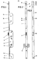
- the espagnolette has a cuff 1.
- a middle control lock 2 and an additional lock 3 are attached to the same on both sides thereof.
- the control lock 2 has a latch 4 which can be retracted by means of a nut 5 mounted in the control lock. Below the nut 5, the operating lock receives a profile lock cylinder 6. When the key is actuated, a drive rod 7 emerging from the operating lock 2 is either shifted in one direction or the other, depending on the direction of rotation of the lock bit of the profile locking cylinder 6.
- the drive rod 7 passes through the additional locks 3 and carries beyond the same locking pin 8.
- corresponding longitudinal slots 9 are provided in the cuff 1 for the locking pin.
- Each additional lock 3 has a lock base 10, from which a bend 11 extends, which in turn is firmly connected to the cuff 1.
- Fixed studs 12, 13 also extend from the additional lock base 10.
- a castle ceiling 14 is supported, which covers the interior of the additional lock 3 with an angled edge.
- a slide bolt 15 is guided in the central region of the additional lock 3.
- the latter is composed of a bolt head 15 'and a bolt tail 15 ".
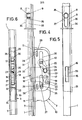
- the bolt 15 is provided in the region of the tail of the tail a guide through a guide pin 17 extending from it, which engages in a slot 18 of the additional lock base 10 which extends in the closing direction of the slide bolt 15.
- the guide pin 17 passes through a window 19 of a translation pivoting lever 20 which extends between the additional lock base 10 and the bolt tail 15 " formed as a one-armed lever and supports the standing pin 12, seen from the operating lock, beyond the slide bolt 15 Tie tail 15 "immersed.
- the transmission swivel lever 20 On its central section, the transmission swivel lever 20 has a control pin 23. The latter engages in a slot of a slide 25 designed as a cam 24. This is guided transversely to the direction of exclusion of the slide bolt on the stud 12, 13, which penetrate the corresponding longitudinal guide slots 26, 27 of the slide 25.
- the slide 25 is carried by the drive rod 1.
- the coupling rod 28 extends from the drive rod 1 into the additional lock 3, the square heads 29 of which partially enter into holes 25 'of the slide 25 in a form-fitting manner.
- the drive rod 1 extends between the slide 25 and the bend 11 of the additional lock base 10. For the passage of the slide bolt 1, the drive rod 1 forms an elongated window 30.
- One longitudinal guide slot 26 is formed by a section adjoining the control cam 24. Get lost in detail the longitudinal guide slot 26 and the subsequent control curve 24 Z-shaped.
- the end section 24 'of the control cam 24 extends parallel to the longitudinal guide slot 26 and is located on the side of the slide 25 facing away from the locking head 15'.
- the transition between the longitudinal guide slot 26 and the end section 24 ' is formed by two arcuate sections 24 ", 24 "', which are interconnected by a short, straight-line intermediate section 24"".
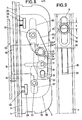
- a striking plate 31 is to be fastened on the fixed frame side. This contains the locking openings 32 for the latch 4 and locking openings 33 for the slide bolts 15 of the additional locks 3. Additional, short locking plates 34 are attached to the locking plate 31. Each of these striking plates 34 acts together with the striker 8 and forms an immersion opening 35 therefor, which continues into a recess 36. The immersion-side end of the recess 36 forms a bevel 37 for the locking pin.
- the locking pin 8 has already run onto the bevel 37 of the striking plate 34 and has forced the door to be moved in the closing direction, so that, as shown in FIG Sliding bolt head 15 'is aligned with the associated closing opening 33.
- the control pin 23 lies within the curved section 24 ′′ of the control cam.
- the transmission pivoting lever 20 has pivoted a small amount in the direction of exclusion and pre-locked the slide bolt by the aforementioned dimension x via the driver pin 21.
- control pin 23 runs through the control cam 24 in connection with a pivoting of the step-up pivot lever 20, which then closes the slide bolt 15 into the position according to FIG. 10. This dips into the closing opening 33.
- the control pin 23 then extends in the rectilinear longitudinal guide slot 26, which adjoins the control curve 24. Accordingly, if the locking forces act on the bolt in the direction of the arrow z, these are in the area between the control pin 23 and the longitudinal Guide slot 26 collected and accordingly not forwarded, so that the operating lock 2 does not have to absorb any push-back forces.
- the free mobility of the translation swivel lever 20 is not impaired due to the window 19, which is penetrated by the guide pin 17.
Landscapes
- Engineering & Computer Science (AREA)
- Mechanical Engineering (AREA)
- Structural Engineering (AREA)
- Lock And Its Accessories (AREA)
- Polysaccharides And Polysaccharide Derivatives (AREA)
- Turning (AREA)
Priority Applications (1)
| Application Number | Priority Date | Filing Date | Title |
|---|---|---|---|
| AT85102635T ATE34200T1 (de) | 1984-05-02 | 1985-03-08 | Treibstangenbeschlag. |
Applications Claiming Priority (2)
| Application Number | Priority Date | Filing Date | Title |
|---|---|---|---|
| DE3416148 | 1984-05-02 | ||
| DE3416148A DE3416148C2 (de) | 1984-05-02 | 1984-05-02 | Treibstangenbeschlag |
Publications (3)
| Publication Number | Publication Date |
|---|---|
| EP0160184A2 true EP0160184A2 (fr) | 1985-11-06 |
| EP0160184A3 EP0160184A3 (en) | 1986-08-13 |
| EP0160184B1 EP0160184B1 (fr) | 1988-05-11 |
Family
ID=6234758
Family Applications (1)
| Application Number | Title | Priority Date | Filing Date |
|---|---|---|---|
| EP85102635A Expired EP0160184B1 (fr) | 1984-05-02 | 1985-03-08 | Espagnolette |
Country Status (3)
| Country | Link |
|---|---|
| EP (1) | EP0160184B1 (fr) |
| AT (1) | ATE34200T1 (fr) |
| DE (2) | DE3416148C2 (fr) |
Cited By (1)
| Publication number | Priority date | Publication date | Assignee | Title |
|---|---|---|---|---|
| FR2687185A1 (fr) * | 1992-02-12 | 1993-08-13 | Vachette Sa | Serrure de porte assurant une fonction d'etancheite et une fonction de securite. |
Families Citing this family (4)
| Publication number | Priority date | Publication date | Assignee | Title |
|---|---|---|---|---|
| DE3544257A1 (de) * | 1985-12-14 | 1987-06-19 | Karrenberg Fa Wilhelm | Antriebsvorrichtung in einem schloss, insbesondere einsteckschloss |
| DE3836693C2 (de) * | 1988-10-28 | 1996-01-25 | Fliether Karl Gmbh & Co | Treibstangenschloß |
| DE3908688C2 (de) * | 1989-03-16 | 1997-06-12 | Gruenzweig & Hartmann Montage | Einsteck- oder Kastenschloß für schalldämmende Türen |
| DE4222629C2 (de) * | 1992-07-10 | 2002-08-01 | Fuhr Carl Gmbh & Co | Treibstangenverschluß mit schlitz/zapfengesteuertem Riegel |
Family Cites Families (4)
| Publication number | Priority date | Publication date | Assignee | Title |
|---|---|---|---|---|
| DE7739940U1 (de) * | 1977-12-29 | 1978-04-06 | Fa. Wilhelm Karrenberg, 5620 Velbert | Treibstangenverschluss, insbesondere fuer wohnungsabschliesstueren |
| DE2929368C2 (de) * | 1979-07-20 | 1984-12-13 | Karl Fliether GmbH & Co, 5620 Velbert | Vorrichtung in einem Treibstangenschloß zum Verhindern des unbefugten Zurückdrückens einer Treibstange aus der Schließstellung |
| FR2469537A1 (fr) * | 1979-11-15 | 1981-05-22 | Gilro | Serrure automatique pour porte d'entree |
| DE3037018C2 (de) * | 1980-10-01 | 1984-08-23 | Karl Fliether GmbH & Co, 5620 Velbert | Vorrichtung zur Vergrößerung des Ausschlußhubes eines eintourigen Schubriegels eines Schlosses |
-
1984
- 1984-05-02 DE DE3416148A patent/DE3416148C2/de not_active Expired
-
1985
- 1985-03-08 EP EP85102635A patent/EP0160184B1/fr not_active Expired
- 1985-03-08 AT AT85102635T patent/ATE34200T1/de not_active IP Right Cessation
- 1985-03-08 DE DE8585102635T patent/DE3562644D1/de not_active Expired
Cited By (2)
| Publication number | Priority date | Publication date | Assignee | Title |
|---|---|---|---|---|
| FR2687185A1 (fr) * | 1992-02-12 | 1993-08-13 | Vachette Sa | Serrure de porte assurant une fonction d'etancheite et une fonction de securite. |
| ES2066709A2 (es) * | 1992-02-12 | 1995-03-01 | Vachette Sa | Cerradura de puerta que asegura una funcion de estanquidad y una funcion de seguridad. |
Also Published As
| Publication number | Publication date |
|---|---|
| ATE34200T1 (de) | 1988-05-15 |
| DE3416148A1 (de) | 1985-11-14 |
| EP0160184B1 (fr) | 1988-05-11 |
| DE3416148C2 (de) | 1986-06-12 |
| DE3562644D1 (de) | 1988-06-16 |
| EP0160184A3 (en) | 1986-08-13 |
Similar Documents
| Publication | Publication Date | Title |
|---|---|---|
| DE3505379C1 (de) | Treibstangenschloß | |
| EP0634552B1 (fr) | Clef avec pêne rotatif, spécialement comme serrure supplémentaire à barres coulissantes | |
| DE10213344A1 (de) | Treibstangenbetätigbarer Hakenriegelverschluss | |
| EP0670403A2 (fr) | Serrure pour porte, notamment serrure encastrée | |
| EP0160184B1 (fr) | Espagnolette | |
| DE3427713C2 (fr) | ||
| DE2738746A1 (de) | Doppeltwirkendes paniktuerschloss mit falle und riegel | |
| DE3148030A1 (de) | Zahnradantrieb in einem schliesszylinderbetaetigbaren treibstangenschloss mit schubriegel | |
| DE2918274A1 (de) | Fehlbedienungssicherung fuer treibstangenbeschlaege | |
| DE4015880C2 (de) | Treibstangenschloß | |
| EP1008713A1 (fr) | Dispositif de verrouillage | |
| EP0454960B1 (fr) | Cremone | |
| DE8413327U1 (de) | Treibstangenbeschlag | |
| EP0662556B1 (fr) | Dispositif de verrouillage pour porte ou fenêtre | |
| EP0091515B1 (fr) | Crémone-serrure | |
| DE3427712A1 (de) | Treibstangenschloss | |
| DE3437268C2 (de) | Türschloß mit Sperrschwenkbügel | |
| EP1425489B1 (fr) | Ferrure oscillobattante | |
| DE4302920C2 (de) | Schloß, insbesondere Einsteckschloß | |
| EP0298292A2 (fr) | Serrure de porte à pêne et demi-tour coulissants | |
| EP0990758A2 (fr) | Serrure additionelle pour crémone | |
| DE9218194U1 (de) | Treibstangenverschluß mit schlitz/zapfengesteuertem Riegel | |
| DE3807338A1 (de) | Schloss, insbesondere einsteckschloss | |
| DE2048685C3 (de) | Links/Rechts durch Umwenden verwendbares Schloß | |
| DE2727527C2 (de) | Vorrichtung zur Vergrößerung des Ausschlusses eines eintourigen Schubriegels eines Schlosses |
Legal Events
| Date | Code | Title | Description |
|---|---|---|---|
| PUAI | Public reference made under article 153(3) epc to a published international application that has entered the european phase |
Free format text: ORIGINAL CODE: 0009012 |
|
| AK | Designated contracting states |
Designated state(s): AT BE CH DE FR GB IT LI LU NL SE |
|
| PUAL | Search report despatched |
Free format text: ORIGINAL CODE: 0009013 |
|
| AK | Designated contracting states |
Kind code of ref document: A3 Designated state(s): AT BE CH DE FR GB IT LI LU NL SE |
|
| 17P | Request for examination filed |
Effective date: 19861107 |
|
| 17Q | First examination report despatched |
Effective date: 19870701 |
|
| GRAA | (expected) grant |
Free format text: ORIGINAL CODE: 0009210 |
|
| AK | Designated contracting states |
Kind code of ref document: B1 Designated state(s): AT BE CH DE FR GB IT LI LU NL SE |
|
| REF | Corresponds to: |
Ref document number: 34200 Country of ref document: AT Date of ref document: 19880515 Kind code of ref document: T |
|
| GBT | Gb: translation of ep patent filed (gb section 77(6)(a)/1977) | ||
| REF | Corresponds to: |
Ref document number: 3562644 Country of ref document: DE Date of ref document: 19880616 |
|
| ET | Fr: translation filed | ||
| ITF | It: translation for a ep patent filed | ||
| PG25 | Lapsed in a contracting state [announced via postgrant information from national office to epo] |
Ref country code: GB Effective date: 19890308 Ref country code: AT Effective date: 19890308 |
|
| PG25 | Lapsed in a contracting state [announced via postgrant information from national office to epo] |
Ref country code: SE Effective date: 19890309 |
|
| PLBE | No opposition filed within time limit |
Free format text: ORIGINAL CODE: 0009261 |
|
| STAA | Information on the status of an ep patent application or granted ep patent |
Free format text: STATUS: NO OPPOSITION FILED WITHIN TIME LIMIT |
|
| PG25 | Lapsed in a contracting state [announced via postgrant information from national office to epo] |
Ref country code: LU Free format text: LAPSE BECAUSE OF NON-PAYMENT OF DUE FEES Effective date: 19890331 Ref country code: LI Effective date: 19890331 Ref country code: CH Effective date: 19890331 Ref country code: BE Effective date: 19890331 |
|
| 26N | No opposition filed | ||
| BERE | Be: lapsed |
Owner name: CARL FUHR G.M.B.H. & CO. Effective date: 19890331 |
|
| PG25 | Lapsed in a contracting state [announced via postgrant information from national office to epo] |
Ref country code: NL Effective date: 19891001 |
|
| GBPC | Gb: european patent ceased through non-payment of renewal fee | ||
| NLV4 | Nl: lapsed or anulled due to non-payment of the annual fee | ||
| REG | Reference to a national code |
Ref country code: CH Ref legal event code: PL |
|
| ITTA | It: last paid annual fee | ||
| PGFP | Annual fee paid to national office [announced via postgrant information from national office to epo] |
Ref country code: FR Payment date: 19920124 Year of fee payment: 8 |
|
| PGFP | Annual fee paid to national office [announced via postgrant information from national office to epo] |
Ref country code: DE Payment date: 19920309 Year of fee payment: 8 |
|
| PG25 | Lapsed in a contracting state [announced via postgrant information from national office to epo] |
Ref country code: FR Effective date: 19931130 |
|
| PG25 | Lapsed in a contracting state [announced via postgrant information from national office to epo] |
Ref country code: DE Effective date: 19931201 |
|
| REG | Reference to a national code |
Ref country code: FR Ref legal event code: ST |
|
| EUG | Se: european patent has lapsed |
Ref document number: 85102635.1 Effective date: 19891016 |