EP0160184A2 - Espagnolette - Google Patents
Espagnolette Download PDFInfo
- Publication number
- EP0160184A2 EP0160184A2 EP85102635A EP85102635A EP0160184A2 EP 0160184 A2 EP0160184 A2 EP 0160184A2 EP 85102635 A EP85102635 A EP 85102635A EP 85102635 A EP85102635 A EP 85102635A EP 0160184 A2 EP0160184 A2 EP 0160184A2
- Authority
- EP
- European Patent Office
- Prior art keywords
- bolt
- slide
- lock
- pin
- slot
- Prior art date
- Legal status (The legal status is an assumption and is not a legal conclusion. Google has not performed a legal analysis and makes no representation as to the accuracy of the status listed.)
- Granted
Links
Images


Classifications
-
- E—FIXED CONSTRUCTIONS
- E05—LOCKS; KEYS; WINDOW OR DOOR FITTINGS; SAFES
- E05B—LOCKS; ACCESSORIES THEREFOR; HANDCUFFS
- E05B63/00—Locks or fastenings with special structural characteristics
- E05B63/0017—Locks with sliding bolt without provision for latching
- E05B63/0021—Locks with sliding bolt without provision for latching the bolt being shot over an increased length by a single turning operation of the key
-
- E—FIXED CONSTRUCTIONS
- E05—LOCKS; KEYS; WINDOW OR DOOR FITTINGS; SAFES
- E05C—BOLTS OR FASTENING DEVICES FOR WINGS, SPECIALLY FOR DOORS OR WINDOWS
- E05C9/00—Arrangements of simultaneously actuated bolts or other securing devices at well-separated positions on the same wing
- E05C9/02—Arrangements of simultaneously actuated bolts or other securing devices at well-separated positions on the same wing with one sliding bar for fastening when moved in one direction and unfastening when moved in opposite direction; with two sliding bars moved in the same direction when fastening or unfastening
- E05C9/026—Arrangements of simultaneously actuated bolts or other securing devices at well-separated positions on the same wing with one sliding bar for fastening when moved in one direction and unfastening when moved in opposite direction; with two sliding bars moved in the same direction when fastening or unfastening comprising key-operated locks, e.g. a lock cylinder to drive auxiliary deadbolts or latch bolts
Landscapes
- Engineering & Computer Science (AREA)
- Mechanical Engineering (AREA)
- Structural Engineering (AREA)
- Lock And Its Accessories (AREA)
- Polysaccharides And Polysaccharide Derivatives (AREA)
- Turning (AREA)
Abstract
Description
Die Erfindung betrifft einen Treibstangenbeschlag gemäß Oberbegriff des Anspruchs 1.The invention relates to an espagnolette fitting according to the preamble of
Ein derartiger Treibstangenbeschlag ist aus dem DE-GM 7 739 940 bekannt, wobei der Riegel als Schwenkriegel ausgebildet ist derart, daß bei einer Längsverschiebung der Treibstange über die Schlitz/Zapfenverbindung der Schwenkriegel um einen gehäusefesten Zapfen des Zusatzschlosses verlagert wird. Auf den vorgeschlossenen Schwenkriegel einwirkende Rückdrückkräfte müssen demzufolge vom Bedienungsschloß aufgefangen werden. Auch ist ein größeres Vorschwenken des Riegels über die Stulpe mit einem größeren Weg der Treibstange verbunden.Such an espagnolette fitting is known from DE-GM 7 739 940, the bolt being designed as a pivot bolt such that the pivot bolt is displaced about a pivot of the auxiliary lock fixed to the housing when the driving rod is displaced longitudinally via the slot / journal connection. Push-back forces acting on the pre-locked swivel bolt must therefore be absorbed by the control lock. A larger forward pivoting of the bolt over the cuff is associated with a larger path of the drive rod.
Dem Gegenstand der Erfindung liegt die Aufgabe zugrunde, einen Treibstangenbeschlag der vorausgesetzten Art so auszugestalten, daß einerseits auf den vorgeschlossenen Riegel einwirkende Rückdrückkräfte nicht auf das Bedienungsschloß übertragen werden und andererseits mit einem geringen Treibstangenweg ein großer Hub des Riegels erreichbar ist.The object of the invention is based on the object of designing an espagnolette fitting of the prerequisite in such a way that, on the one hand, push-back forces acting on the pre-locked bolt are not transmitted to the operating lock and, on the other hand, a large stroke of the bolt can be reached with a small espagnolette travel.
Gelöst wird diese Aufgabe durch das Kennzeichen des Anspruchs 1.This problem is solved by the characterizing part of
Zufolge derartiger Ausgestaltung ist ein gattungsgemäßer Treibstangenbeschlag von erhöhtem Sicherheitswert angegeben. Der von der Steuerkurve des Schiebers verlagerbare Obersetzungs-Schwenkhebel gestattet bei geringem Hub der Treibstange ein weites Vorschließen des Riegels. Auch ist hierbei eine große Leichtgängigkeit gegeben. Trotzdem ist der Schubriegel gegen Zurückdrücken durch das Zusammenwirken von Übersetzungs-Schwenkhebel und Schieber gesperrt, so daß Rückdrückkräfte nicht in das Bedienungsschloß eingeleitet werden.As a result of such a configuration, a generic connecting rod fitting with an increased security value is specified. The step-up swivel lever, which can be displaced from the control curve of the slide, allows a wide advance with a small stroke of the drive rod of the bolt. There is also great ease of movement here. Nevertheless, the slide bolt is locked against pushing back by the interaction of the translation pivot lever and slide, so that push-back forces are not introduced into the control lock.
Eine vorteilhafte Weiterbildung ist darin zu sehen, daß der Schubriegel mittels eines ein Fenster des Übersetzungs-Schwenkhebeis durchsetzenden Führungszapfens in einen Schlitz des Zusatzschloßbodens eingreift. Trotz Zusammenwirken des Schubriegels mit dem Übersetzungs-Schwenkhebel wird die Führung des Schubriegels nicht beeinträchtigt. Ausgenutzt ist zu diesem Zweck auch die Tatsache, daß sich der Übersetzungs-Schwenkhebei und Schubriegel bei ihrer Verlagerung stets in gleicher Richtung bewegen, so daß durch das Fenster der Übersetzungs-Schwenkhebel keine gefährdende Schwächung erfährt.An advantageous further development is to be seen in the fact that the slide bolt engages in a slot of the additional lock base by means of a guide pin passing through a window of the transmission pivoting lever. Despite the interaction of the slide bolt with the transmission swivel lever, the guidance of the slide bolt is not impaired. Also used for this purpose is the fact that the translation pivoting lever and slide bolt always move in the same direction when they are relocated, so that the translation pivoting lever does not experience any dangerous weakening through the window.
Schließtechnische Vorteile bringt es, daß das Zusatzschloß zwischen Bedienungsschloß und Treibstangen-Schließzapfen angeordnet ist. Hierdurch wird der Sicherheitswert zusätzlich noch erhöht. Die Treibstange, die den Schubriegel steuert, dient gleichzeitig als tragendes Element für die Schließzapfen.There are advantages in terms of locking technology in that the additional lock is arranged between the operating lock and the espagnolette locking pin. This increases the safety value even more. The drive rod, which controls the slide bolt, also serves as a load-bearing element for the locking pin.
Darüber hinaus ist es bautechnisch günstig, daß der Schubriegel durch ein Fenster der Treibstange greift, welche mit in das Zusatzschloß hineinragenden Kupplungszapfen ausgestattet ist, deren Köpfe in formschlüssigem Eingriff stehen zu Löchern des Schiebers, welcher Längs-Führungsschlitze besitzt, in die Stehzapfen des Zusatzschloßbodens ragen. Hierdurch wird eine stabile Kupplung zwischen Treibstange und Schieber erreicht. Der Schieber erhält seine Führung durch die ortsfesten Stehzapfen. Da der Schieber auch in Eingriff steht zu den Köpfen der Kupplungszapfen der Treibstange, wird hierdurch die Lage der Treibstange im Zusatzschloß stabilisiert, was zu einem störungsfreien Schließen des Zusatzschlosses führt.In addition, it is structurally advantageous that the slide bolt engages through a window of the drive rod, which is equipped with coupling pins protruding into the additional lock, the heads of which are in positive engagement with holes in the slide, which has longitudinal guide slots, protrude into the studs of the additional lock base . This ensures a stable coupling between the drive rod and slide. The slide receives its guidance through the stationary studs. Since the slide is also engaged with the heads of the coupling pins of the drive rod, the position of the drive rod in the additional lock is thereby stabilized, which leads to a trouble-free closing of the additional lock.
Dabei erweist es sich als vorteilhaft, daß der eine Längs-Führungsschlitz von einem sich an die Steuerkurve anschließenden Abschnitt gebildet ist. Hierdurch erfüllt dieser Längs-Führungsschlitz eine Doppelfunktion.It proves to be advantageous that the one longitudinal guide slot is formed by a section adjoining the control curve. As a result, this longitudinal guide slot fulfills a double function.
Endlich bringt es noch schließtechnische Vorteile, daß die Schließzapfen dem Ausschluß des Schubriegels voreiien. Dann werden beim Abschließen des Treibstangenbeschlages erst die Schließzapfen in Eingriff zu den ihnen zugeordneten Schließblechen des Festrahmens gebracht, wodurch über entsprechende Auflaufschrägen des Schließbleches ein Anziehen des Türbeschlages in Richtung des Festrahmens erfolgt. Hierbei erfährt der Schubriegel eine Ausrichtung auf die ihm zugeordnete Schließöffnung des Schließbleches, so daß er, dem Schließzapfen nachfolgend, störungsfrei in die Schließöffnung eintreten kann. Diese Maßnahme erweist sich insbesondere als vorteilhaft, wenn es sich um hohe Türen handelt, die zum Verziehen neigen.Finally, there are still advantages in terms of locking technology in that the locking pins advance the exclusion of the slide bolt. Then, when the espagnolette fitting is locked, the locking pins are first brought into engagement with the locking plates of the fixed frame assigned to them, which means that the door fitting is tightened in the direction of the fixed frame via corresponding run-on slopes of the locking plate. Here, the slide bolt is aligned with the locking opening of the locking plate assigned to it, so that it can enter the locking opening without interference, following the locking pin. This measure proves to be particularly advantageous when the doors are high and tend to warp.
Nachstehend wird ein Ausführungsbeispiel der Erfindung anhand der Fig. 1-10 erläutert. Es zeigt
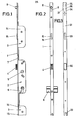
- Fig. 1 eine Ansicht eines Treibstangenbeschlages,
- Fig. 2 eine klappfigürliche Ansicht der Fig. 1,
- Fig. 3 eine Ansicht des festrahmenseitigen Schließbleches,
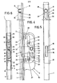
- Fig. 4 in etwa natürlichem Maßstab eine Ansicht des Zusatzschlosses, wobei die Schloßdecke entfernt ist,
- Fig. 5 eine klappfigürliche Ansicht der Fig. 4,
- Fig. 6 eine Rückansicht des Zusatzschlosses,
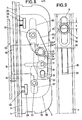
- Fig. 7 in vergrößerter Darstellung das Zusatzschloß bei fortgelassener Schloßdecke und strichpunktiert veranschaulichtem Schieber gemäß der zurückgezogenen Stellung des Schubriegels,
- Fig. 8 eine der Fig. 7 entsprechende Darstellung, wobei der Schubriegel um ein geringes Maß vorgeschlossen ist,
- Fig. 9 die der Fig. 8 entsprechende Stellung des voreilenden Schließzapfens während des Eintretens in die ihm zugeordnete Schließausnehmung und
- Fig. 10 eine der Fig. 7 entsprechende Darstellung, wobei der Schubriegel vollständig vorgeschlossen ist.
- 1 is a view of an espagnolette fitting,
- FIG. 2 is a collapsible view of FIG. 1,
- 3 is a view of the striker plate on the fixed frame,
- 4 is a view of the additional lock on an approximately natural scale, the lock cover being removed,
- 5 is a collapsible view of FIG. 4,
- 6 is a rear view of the additional lock,
- 7 is an enlarged view of the additional lock with the lock cover omitted and the slider shown in dash-dot lines in accordance with the retracted position of the slide bolt,
- 8 is a representation corresponding to FIG. 7, the slide bolt being pre-locked to a small extent,
- FIG. 9 shows the position of the leading locking pin corresponding to FIG. 8 as it enters the locking recess assigned to it and
- Fig. 10 is a representation corresponding to Fig. 7, wherein the slide bolt is fully locked.
Der Treibstangenbeschiag besitzt eine Stulpe 1. An diese ist ein mittleres Bedienungsschloß 2 und beidseitig desselben je ein Zusatzschloß 3 angesetzt. Das Bedienungsschloß 2 weist eine Falle 4 auf, die mittels einer im Bedienungsschloß gelagerten Nuß 5 zurückziehbar ist. Unterhalb der Nuß 5 nimmt das Bedienungsschloß einen Profilschließzylinder 6 auf. Bei Schlüsselbetätigung wird eine aus dem Bedienungsschloß 2 austretende Treibstange 7 entweder in der einen oder anderen Richtung verlagert, und zwar in Abhängigkeit vom Drehsinn des Schließbartes des Profilschließzylinders 6.The espagnolette has a
Die Treibstange 7 durchsetzt die Zusatzschlösser 3 und trägt jenseits derselben Schließzapfen 8. Zu diesem Zweck sind in der Stulpe 1 entsprechende Längsschlitze 9 für die Schließzapfen vorgesehen.The
Jedes Zusatzschloß 3 besitzt einen Schloßboden 10, von welcher eine Abwinklung 11 ausgeht, die ihrerseits fest mit der Stulpe 1 verbunden ist. Vom Zusatzschloßboden 10 gehen ferner ortsfeste Stehzapfen 12, 13 aus. Auf diesen stützt sich eine Schloßdecke 14 ab, die mit einem abgewinkelten Rand das Eingerichte des Zusatzschlosses 3 überfängt. Im Mittelbereich des Zusatzschlosses 3 ist ein Schubriegel 15 geführt. Letzterer setzt sich aus einem Riegelkopf 15' und einem Riegelschwanz 15" zusammen. Für den Riegelkopf 15' ist in der Stulpe 1 eine dem Riegelkopf querschnittsangepaßte Ausnehmung 16 vorgesehen, die einerseits zur Führung des Riegels 15 dient. Andererseits erhält der Riegel 15 im riegeischwanzseitigen Bereich eine Führung durch einen von ihm ausgehenden Führungszapfen 17, der in einen in Schließrichtung des Schubriegels 15 verlaufenden Schlitz 18 des Zusatzschloßbodens 10 eingreift. Der Führungszapfen 17 durchsetzt ein Fenster 19 eines sich zwischen Zusatzschloßboden 10 und Riegelschwanz 15" erstreckenden Übersetzungs-Schwenkhebels 20. Letzterer ist als einarmiger Hebel ausgebildet und lagert um den, vom Bedienungsschloß aus gesehen, jenseits des Schubriegels 15 liegenden Stehzapfen 12. Das freie Ende des Übersetzungs-Schwenkhebels 20 ist mit einem Mitnehmerzapfen 21 bestückt, der in einen quer zur Schließrichtung des Schubriegels 15 verlaufenden Kupplungsschlitz 22 des Riegelschwanzes 15" eintaucht. Auf seinem Mittelabschnitt besitzt der Übersetzungs-Schwenkhebel 20 einen Steuerzapfen 23. Letzterer greift in einen als Steuerkurve 24 ausgebildeten Schlitz eines Schiebers 25 ein. Dieser ist quer zur Ausschlußrichtung des Schubriegels auf den Stehzapfen 12, 13 geführt, die entsprechende Längs-Führungsschlitze 26, 27 des Schiebers 25 durchsetzen.Each
Mitgenommen wird der Schieber 25 von der Treibstange 1. Zu diesem Zweck gehen von der Treibstange 1 in das Zusatzschloß 3 hineinragende Kupplungszapfen 28 aus, deren vierkantige Köpfe 29 mit einem Teil formschlüssig in Löcher 25' des Schiebers 25 eintreten. Die Treibstange 1 erstreckt sich zwischen dem Schieber 25 und der Abwinklung 11 des Zusatzschloßbodens 10. Zum Durchtritt des Schubriegels 1 bildet die Treibstange 1 ein langgestrecktes Fenster 30 aus.The
Der eine Längs-Führungsschlitz 26 ist von einem sich an die Steuerkurve 24 anschließenden Abschnitt gebildet. Im einzelnen verlaufen der Längs-Führungsschlitz 26 und die sich anschließende Steuerkurve 24 Z-förmig. Der Endabschnitt 24' der Steuerkurve 24 erstreckt sich parallel zum Längs-Führungsschlitz 26 und befindet sich auf der dem Riegelkopf 15' abgewendeten Seite des Schiebers 25. Den Übergang zwischen dem Längs-Führungsschlitz 26 und Endabschnitt 24' bilden zwei bogenförmige Abschnitte 24", 24"', die durch einen kurzen, geradlinig verlaufenden Zwischenabschnitt 24"" untereinander verbunden sind. Bei zurückgeschlossenem Schubriegel 15, vergl. insbesondere Fig. 7, befindet sich der Steuerzapfen 23 des Übersetzungs-Schwenkhebels 20 in dem Endabschnitt 24' der Steuerkurve 24.One
Festrahmenseitig ist ein Schließblech 31 zu befestigen. Dieses enthält die Schließöffnungen 32 für die Falle 4 und Schließöffnungen 33 für die Schubriegel 15 der Zusatzschlösser 3. An das Schließblech 31 fügen sich weitere, kurze Schließbleche 34 an. Jedes dieser Schließbleche 34 wirkt zusammen mit dem Schließzapfen 8 und formt für diesen eine Eintauchöffnung 35, die sich In eine Nische 36 fortsetzt. Das eintauchseitige Ende der Nische 36 bildet eine Anzugsschräge 37 für den Schließzapfen.A
Es ergibt sich folgende Wirkungsweise: Soll nach dem Zuschlagen der Türe der Treibstangenbeschlag in Verriegelungsstellung gebracht werden, so geschieht dieses durch Schlüsselbetätigung. Einhergehend damit wird die Treibstange 7 verlagert. Der Steuerzapfen 23 und die Steuerkurve 24 sind dabei so aufeinander abgestimmt, daß die Schließzapfen 8 dem Ausschluß des Schubriegels 15 voreilen. Das bedeutet, daß, wie in Fig. 8 und 9 dargestellt ist, der Schubriegel 15 um das Maß x vorgeschlossen ist, während der Schließzapfen 8 sich um das Maß y bewegt hat. Es ist ohne weiteres ersichtlich, daß das Maß y ein mehrfaches des Maßes x ist. Demgemäß hat der Schubriegel 15 noch nicht das Schließblech 31 erreicht. Der Schließzapfen 8 ist jedoch bereits auf die Anzugsschräge 37 des Schließbleches 34 aufgelaufen und hat dabei eine Anzugsverlagerung der Türe in SchJießrichtung erzwungen, so daß dann, wie Fig. 9 veranschaulicht, der Schubriegelkopf 15' mit der zugeordneten Schließöffnung 33 fluchtet. In dieser Schließphase liegt der Steuerzapfen 23 innerhalb des Bogenabschnittes 24" der Steuerkurve. Demzufolge hat sich der Übersetzungs-Schwenkhebel 20 um ein geringes Maß in Ausschließrichtung verschwenkt und über den Mitnehmerzapfen 21 den Schubriegel um das vorerwähnte Maß x vorgeschlossen.This results in the following mode of operation: If the espagnolette fitting is to be brought into the locked position after the door has slammed, this is done by actuating a key. Along with this, the
Bei fortschreitender Schließbetätigung durchläuft der Steuerzapfen 23 die Steuerkurve 24 verbunden mit einem Verschwenken des Obersetzungs-Schwenkhebels 20, welcher dann den Schubriegel 15 in die Lage gemäß Fig. 10 vorschließt. Dieser taucht dabei in die Schließöffnung 33 ein. In der vorgeschlossenen Stellung erstreckt sich dann der Steuerzapfen 23 in dem geradlinigen Längs-Führungsschlitz 26, welcher sich an die Steuerkurve 24 anschließt.- Wirken demgemäß Rückdrückkräfte auf den Riegel in Pfeilrichtung z, so werden diese im Bereich zwischen dem Steuerzapfen 23 und dem Längs-Führungsschlitz 26 aufgefangen und demgemäß nicht weitergeleitet, wodurch das Bedienungsschloß 2 keine Rückdrückkräfte aufnehmen muß.As the closing operation progresses, the
Da die Anlenkstelle des Übersetzungs-Schwenkhebels 20 sich auf der einen Seite des Schubriegels 15 befindet und der Kupplungspunkt sich im Bereich der anderen Seite des Schubriegels erstreckt, wird ein großer Ausschluß des Schubriegels verwirklicht.Since the articulation point of the
Die freie Beweglichkeit des Übersetzungs-Schwenkhebeis 20 ist nicht beeinträchtigt zufolge des Fensters 19, welcher vom Führungszapfen 17 durchsetzt wird.The free mobility of the
Alle in der Beschreibung erwähnten und in der Zeichnung dargestellten neuen Merkmale sind erfindungswesentlich, auch soweit sie in den Ansprüchen nicht ausdrücklich beansprucht sind.All the new features mentioned in the description and shown in the drawing are essential to the invention, even if they are not expressly claimed in the claims.
Claims (6)
Priority Applications (1)
| Application Number | Priority Date | Filing Date | Title |
|---|---|---|---|
| AT85102635T ATE34200T1 (en) | 1984-05-02 | 1985-03-08 | DRIVING ROD FITTING. |
Applications Claiming Priority (2)
| Application Number | Priority Date | Filing Date | Title |
|---|---|---|---|
| DE3416148 | 1984-05-02 | ||
| DE3416148A DE3416148C2 (en) | 1984-05-02 | 1984-05-02 | Espagnolette |
Publications (3)
| Publication Number | Publication Date |
|---|---|
| EP0160184A2 true EP0160184A2 (en) | 1985-11-06 |
| EP0160184A3 EP0160184A3 (en) | 1986-08-13 |
| EP0160184B1 EP0160184B1 (en) | 1988-05-11 |
Family
ID=6234758
Family Applications (1)
| Application Number | Title | Priority Date | Filing Date |
|---|---|---|---|
| EP85102635A Expired EP0160184B1 (en) | 1984-05-02 | 1985-03-08 | Espagnolette |
Country Status (3)
| Country | Link |
|---|---|
| EP (1) | EP0160184B1 (en) |
| AT (1) | ATE34200T1 (en) |
| DE (2) | DE3416148C2 (en) |
Cited By (1)
| Publication number | Priority date | Publication date | Assignee | Title |
|---|---|---|---|---|
| FR2687185A1 (en) * | 1992-02-12 | 1993-08-13 | Vachette Sa | Door lock affording a sealing function and a security function |
Families Citing this family (4)
| Publication number | Priority date | Publication date | Assignee | Title |
|---|---|---|---|---|
| DE3544257A1 (en) * | 1985-12-14 | 1987-06-19 | Karrenberg Fa Wilhelm | Drive device in a lock, especially a mortice lock |
| DE3836693C2 (en) * | 1988-10-28 | 1996-01-25 | Fliether Karl Gmbh & Co | Espagnolette lock |
| DE3908688C2 (en) * | 1989-03-16 | 1997-06-12 | Gruenzweig & Hartmann Montage | Mortise or case lock for soundproof doors |
| DE4222629C2 (en) * | 1992-07-10 | 2002-08-01 | Fuhr Carl Gmbh & Co | Espagnolette lock with slot / pin-controlled bolt |
Citations (2)
| Publication number | Priority date | Publication date | Assignee | Title |
|---|---|---|---|---|
| FR2469537A1 (en) * | 1979-11-15 | 1981-05-22 | Gilro | Key-actuated multi-bolt lock external door - uses retraction latch bolt at closure to trigger partial emergence casement bolts and dead bolt |
| DE3037018A1 (en) * | 1980-10-01 | 1982-04-22 | Fa. Karl Fliether, 5620 Velbert | Mortise lock with extended bolt travel - has slide-type transfer element with concave control cam meshing with intermediate link |
Family Cites Families (2)
| Publication number | Priority date | Publication date | Assignee | Title |
|---|---|---|---|---|
| DE7739940U1 (en) * | 1977-12-29 | 1978-04-06 | Fa. Wilhelm Karrenberg, 5620 Velbert | DRIVE ROD LOCK, IN PARTICULAR FOR APARTMENT LOCKING CONTROLS |
| DE2929368C2 (en) * | 1979-07-20 | 1984-12-13 | Karl Fliether GmbH & Co, 5620 Velbert | Device in a connecting rod lock for preventing unauthorized pushing back of a connecting rod from the closed position |
-
1984
- 1984-05-02 DE DE3416148A patent/DE3416148C2/en not_active Expired
-
1985
- 1985-03-08 DE DE8585102635T patent/DE3562644D1/en not_active Expired
- 1985-03-08 AT AT85102635T patent/ATE34200T1/en not_active IP Right Cessation
- 1985-03-08 EP EP85102635A patent/EP0160184B1/en not_active Expired
Patent Citations (2)
| Publication number | Priority date | Publication date | Assignee | Title |
|---|---|---|---|---|
| FR2469537A1 (en) * | 1979-11-15 | 1981-05-22 | Gilro | Key-actuated multi-bolt lock external door - uses retraction latch bolt at closure to trigger partial emergence casement bolts and dead bolt |
| DE3037018A1 (en) * | 1980-10-01 | 1982-04-22 | Fa. Karl Fliether, 5620 Velbert | Mortise lock with extended bolt travel - has slide-type transfer element with concave control cam meshing with intermediate link |
Cited By (2)
| Publication number | Priority date | Publication date | Assignee | Title |
|---|---|---|---|---|
| FR2687185A1 (en) * | 1992-02-12 | 1993-08-13 | Vachette Sa | Door lock affording a sealing function and a security function |
| ES2066709A2 (en) * | 1992-02-12 | 1995-03-01 | Vachette Sa | Door lock providing both sealing and security functions - has head on which compressible seal is relatively pushed and displaceable rod against head piece |
Also Published As
| Publication number | Publication date |
|---|---|
| EP0160184A3 (en) | 1986-08-13 |
| DE3562644D1 (en) | 1988-06-16 |
| EP0160184B1 (en) | 1988-05-11 |
| DE3416148A1 (en) | 1985-11-14 |
| ATE34200T1 (en) | 1988-05-15 |
| DE3416148C2 (en) | 1986-06-12 |
Similar Documents
| Publication | Publication Date | Title |
|---|---|---|
| DE3505379C1 (en) | Espagnolette lock | |
| EP0634552B1 (en) | Key with rotary bolt, especially as supplementary lock on sliding bars | |
| EP0670403B1 (en) | Doorlock, especially mortise lock | |
| EP0160184B1 (en) | Espagnolette | |
| DE3148031C2 (en) | ||
| EP0091517B1 (en) | Sliding bar lock with closing cylinder | |
| DE2738746B2 (en) | Release device for a panic door lock with latch and bolt | |
| DE4015880C2 (en) | Espagnolette lock | |
| DE2918274A1 (en) | Window or door wing fail safe security mechanism - has drive rod passing through housing containing bolt locking against cam | |
| DE3816341C2 (en) | ||
| DE3427713C2 (en) | ||
| DE19934456A1 (en) | Locking device | |
| DE3316261C2 (en) | ||
| DE3213452C2 (en) | Change lever actuation device in a cylinder-actuated espagnolette lock | |
| EP0990758A2 (en) | Additional lock for espagnolette | |
| DE3427712A1 (en) | Espagnolette lock | |
| DE3920498C2 (en) | Multiple locking | |
| DE4302920C2 (en) | Lock, especially mortise lock | |
| DE3544257C2 (en) | ||
| EP0806534B1 (en) | Espagnolette | |
| EP0298292A2 (en) | Door lock with sliding bolt and latch | |
| DE2048685C3 (en) | Lock that can be used by turning left / right | |
| DE2727527C2 (en) | Device for increasing the exclusion of a single-turn sliding bolt of a lock | |
| EP1425489B1 (en) | Side/bottom fitting | |
| EP0662556A1 (en) | Locking device for a door or a window |
Legal Events
| Date | Code | Title | Description |
|---|---|---|---|
| PUAI | Public reference made under article 153(3) epc to a published international application that has entered the european phase |
Free format text: ORIGINAL CODE: 0009012 |
|
| AK | Designated contracting states |
Designated state(s): AT BE CH DE FR GB IT LI LU NL SE |
|
| PUAL | Search report despatched |
Free format text: ORIGINAL CODE: 0009013 |
|
| AK | Designated contracting states |
Kind code of ref document: A3 Designated state(s): AT BE CH DE FR GB IT LI LU NL SE |
|
| 17P | Request for examination filed |
Effective date: 19861107 |
|
| 17Q | First examination report despatched |
Effective date: 19870701 |
|
| GRAA | (expected) grant |
Free format text: ORIGINAL CODE: 0009210 |
|
| AK | Designated contracting states |
Kind code of ref document: B1 Designated state(s): AT BE CH DE FR GB IT LI LU NL SE |
|
| REF | Corresponds to: |
Ref document number: 34200 Country of ref document: AT Date of ref document: 19880515 Kind code of ref document: T |
|
| GBT | Gb: translation of ep patent filed (gb section 77(6)(a)/1977) | ||
| REF | Corresponds to: |
Ref document number: 3562644 Country of ref document: DE Date of ref document: 19880616 |
|
| ET | Fr: translation filed | ||
| ITF | It: translation for a ep patent filed |
Owner name: STUDIO JAUMANN |
|
| PG25 | Lapsed in a contracting state [announced via postgrant information from national office to epo] |
Ref country code: GB Effective date: 19890308 Ref country code: AT Effective date: 19890308 |
|
| PG25 | Lapsed in a contracting state [announced via postgrant information from national office to epo] |
Ref country code: SE Effective date: 19890309 |
|
| PLBE | No opposition filed within time limit |
Free format text: ORIGINAL CODE: 0009261 |
|
| STAA | Information on the status of an ep patent application or granted ep patent |
Free format text: STATUS: NO OPPOSITION FILED WITHIN TIME LIMIT |
|
| PG25 | Lapsed in a contracting state [announced via postgrant information from national office to epo] |
Ref country code: LU Free format text: LAPSE BECAUSE OF NON-PAYMENT OF DUE FEES Effective date: 19890331 Ref country code: LI Effective date: 19890331 Ref country code: CH Effective date: 19890331 Ref country code: BE Effective date: 19890331 |
|
| 26N | No opposition filed | ||
| BERE | Be: lapsed |
Owner name: CARL FUHR G.M.B.H. & CO. Effective date: 19890331 |
|
| PG25 | Lapsed in a contracting state [announced via postgrant information from national office to epo] |
Ref country code: NL Effective date: 19891001 |
|
| GBPC | Gb: european patent ceased through non-payment of renewal fee | ||
| NLV4 | Nl: lapsed or anulled due to non-payment of the annual fee | ||
| REG | Reference to a national code |
Ref country code: CH Ref legal event code: PL |
|
| ITTA | It: last paid annual fee | ||
| PGFP | Annual fee paid to national office [announced via postgrant information from national office to epo] |
Ref country code: FR Payment date: 19920124 Year of fee payment: 8 |
|
| PGFP | Annual fee paid to national office [announced via postgrant information from national office to epo] |
Ref country code: DE Payment date: 19920309 Year of fee payment: 8 |
|
| PG25 | Lapsed in a contracting state [announced via postgrant information from national office to epo] |
Ref country code: FR Effective date: 19931130 |
|
| PG25 | Lapsed in a contracting state [announced via postgrant information from national office to epo] |
Ref country code: DE Effective date: 19931201 |
|
| REG | Reference to a national code |
Ref country code: FR Ref legal event code: ST |
|
| EUG | Se: european patent has lapsed |
Ref document number: 85102635.1 Effective date: 19891016 |