EP0158985B1 - Maschine zum Ausbringen von körnigem Material - Google Patents
Maschine zum Ausbringen von körnigem Material Download PDFInfo
- Publication number
- EP0158985B1 EP0158985B1 EP85104443A EP85104443A EP0158985B1 EP 0158985 B1 EP0158985 B1 EP 0158985B1 EP 85104443 A EP85104443 A EP 85104443A EP 85104443 A EP85104443 A EP 85104443A EP 0158985 B1 EP0158985 B1 EP 0158985B1
- Authority
- EP
- European Patent Office
- Prior art keywords
- grains
- acceleration
- sensor
- disposed
- machine according
- Prior art date
- Legal status (The legal status is an assumption and is not a legal conclusion. Google has not performed a legal analysis and makes no representation as to the accuracy of the status listed.)
- Expired - Lifetime
Links
Images

Classifications
-
- A—HUMAN NECESSITIES
- A01—AGRICULTURE; FORESTRY; ANIMAL HUSBANDRY; HUNTING; TRAPPING; FISHING
- A01C—PLANTING; SOWING; FERTILISING
- A01C15/00—Fertiliser distributors
-
- A—HUMAN NECESSITIES
- A01—AGRICULTURE; FORESTRY; ANIMAL HUSBANDRY; HUNTING; TRAPPING; FISHING
- A01C—PLANTING; SOWING; FERTILISING
- A01C7/00—Sowing
- A01C7/08—Broadcast seeders; Seeders depositing seeds in rows
- A01C7/10—Devices for adjusting the seed-box ; Regulation of machines for depositing quantities at intervals
- A01C7/102—Regulating or controlling the seed rate
-
- A—HUMAN NECESSITIES
- A01—AGRICULTURE; FORESTRY; ANIMAL HUSBANDRY; HUNTING; TRAPPING; FISHING
- A01C—PLANTING; SOWING; FERTILISING
- A01C7/00—Sowing
- A01C7/08—Broadcast seeders; Seeders depositing seeds in rows
- A01C7/10—Devices for adjusting the seed-box ; Regulation of machines for depositing quantities at intervals
- A01C7/102—Regulating or controlling the seed rate
- A01C7/105—Seed sensors
-
- G—PHYSICS
- G05—CONTROLLING; REGULATING
- G05D—SYSTEMS FOR CONTROLLING OR REGULATING NON-ELECTRIC VARIABLES
- G05D7/00—Control of flow
- G05D7/06—Control of flow characterised by the use of electric means
- G05D7/0605—Control of flow characterised by the use of electric means specially adapted for solid materials
- G05D7/0611—Control of flow characterised by the use of electric means specially adapted for solid materials characterised by the set value given to the control element
-
- Y—GENERAL TAGGING OF NEW TECHNOLOGICAL DEVELOPMENTS; GENERAL TAGGING OF CROSS-SECTIONAL TECHNOLOGIES SPANNING OVER SEVERAL SECTIONS OF THE IPC; TECHNICAL SUBJECTS COVERED BY FORMER USPC CROSS-REFERENCE ART COLLECTIONS [XRACs] AND DIGESTS
- Y10—TECHNICAL SUBJECTS COVERED BY FORMER USPC
- Y10S—TECHNICAL SUBJECTS COVERED BY FORMER USPC CROSS-REFERENCE ART COLLECTIONS [XRACs] AND DIGESTS
- Y10S111/00—Planting
- Y10S111/903—Monitor
- Y10S111/904—Population control function
Definitions
- the invention relates to a machine for spreading granular material, in particular seeds, fertilizers, etc. according to the features as specified in the preamble of claims 1, 4 and 6.
- Such a machine is already known from US-A-3 422 776. Below the dosing unit, it is equipped with a sensor plate onto which the dosed grains fall. When the grains hit the sensor plate, it is deflected, thereby generating a pulse that is fed to an evaluation circuit.
- a disadvantage of this known machine is that only sufficiently large and heavy grains are able to actuate the sensor plate in such a way that a clear signal is produced.
- a seed drill or a pneumatic type fertilizer spreader with a metering device and horizontally extending discharge pipes is known. Downward-pointing bends are attached to the lateral ends of the delivery pipes, on the outside of which microphones are provided. The microphones record the volume of the material stream flowing past, the volume then being used to deduce the amount scattered.
- WO-A-8 504 547 which is to be considered as state of the art within the meaning of Art. 54 (3), describes a seeder with metering device and an acceleration device in front of a counting device.
- the counting device consists of a light barrier, which is housed in a tube insert, which has an inner diameter, hardly larger than the grains to be counted.
- the purpose of the acceleration device which is designed as a blower, is to separate the grains in order to prevent two grains from simultaneously entering the counter and clogging it.
- the invention has for its object to improve the detection of the amount of material emitted by the dosing member or the number of material grains by the sensor in a generic device, as specified in the preamble of claims 1, 4 and 6.
- the acceleration device is a blower with a lock. This makes it possible to retrofit the acceleration device even in the smallest of spaces in mass-produced machines with the least constructional and structural effort.
- it is provided to use a conveyor belt as the acceleration device. This type of acceleration device is particularly suitable for granular materials that are coated with dust-like agents.
- a rotating centrifugal disc is used for acceleration.
- the acceleration device is essentially designed so that it can be installed in different positions.
- its acceleration path can be oriented at least approximately horizontally.
- Such an acceleration device can also be used without difficulty for seed drills with a small distance between the metering element and the coulter, the freedom of movement of which must not be restricted.
- the choice of the impact angles with respect to the direction of acceleration in the invention ensures that the grains accelerated in the direction of the impact sensor are not hindered by the grains which have already impacted the sensor.
- An angle of the order of magnitude of 45 ° to 70 ° to the direction of acceleration has proven to be particularly advantageous here, particularly in the case of a horizontal direction of acceleration.
- the impact sensor can be arranged on a sensor plate according to a development of the invention be in which holes are formed at least outside the impact area of the grains.
- the escape of air can also be ensured by arranging at least one open gap on the side of the sensor plate. This measure at least ensures that no air vortices form which could hinder the acceleration of the grains or impair their impact on the sensor plate.
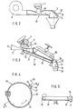
- a storage container 1 of a seed drill has outlet openings 2 in its lower area, above which metering housing 3 with metering elements 4 designed as cam wheels are arranged therein.
- An acceleration device 8 is arranged below the metering housing 3. This consists of a blower 9 driven by a power source (not shown), an injector sluice 10 with an inlet funnel 11 and an acceleration section 13 designed as a tube 12. At the end of the acceleration section 13 is a sensor plate 14 with a sensor 15 at an angle a to the direction of acceleration 16 Acceleration path 13 attached.
- the angle a has a size of approximately 45 °.
- the function of the acceleration device 8 is as follows:
- the seeds 22 located in the storage container 1 are supplied in adjustable quantities or number per distance traveled by the seed drill from the respective metering elements 4 to the coulters 21 and are thus deposited in the ground.
- the metering element 4, under which the acceleration device 8 is arranged feeds the metered seeds 22 via the inlet funnel 11 to the injector sluice 10.
- the seeds 22 are caught by the air flow generated by the fan 9 and accelerated relatively strongly in the direction of the sensor 15 in the region of the acceleration path 13.
- the accelerated seeds 22 then hit the sensor plate 14 with a relatively large kinetic energy.
- the impingement of the seeds 22 on the sensor plate 14 generates pulses, signals or vibrations which are picked up by the sensor 15.
- the seeds 22 After hitting the sensor plate 14, the seeds 22 are deflected downward in the direction of the funnel 19 of the seed tube 20 due to the angle of attack ⁇ of the sensor plate 14 to the acceleration direction 16 of the seeds 22. From here the seeds 22 then fall in free fall over the coulter 21 into the sowing furrow produced by the latter.
- the pulses, signals or vibrations collected by the sensor 15 are fed to a microprocessor 24 via a line 23.
- a distance measuring device 25 is connected to this. This determines the distance covered by the seed drill.
- the determined distance values are also sent to the microprocessor 24. From these values, the microprocessor 24 then calculates the actually applied number of seeds 22 which the metering member 4 has fed to the coulter 21. This determined number of seeds actually applied is then compared in the microprocessor 24 with the target value entered therein.
- the microprocessor sends corresponding signals to a servomotor 26, which then adjusts a control lever 27 of the control gear 6 accordingly, so that the metering element 4 doses the number of seeds corresponding to the target value per distance covered. This control process is repeated continuously.
- the acceleration device 28 according to FIG. 2 differs from the acceleration device 8 according to FIG. 1 only in the different design of the lock.
- the lock of this acceleration device 28 is designed as a cellular wheel lock 29.
- the mode of operation of the acceleration device 28 corresponds to that of the acceleration device 8.
- the acceleration device 30 according to FIG. 3 is also arranged on a seed drill below a metering device 4 and is designed as two conveyor belts 31 and 32 lying one on top of the other.
- the lower conveyor belt 31 extends from the front of the metering device 4 to the funnel 19 of the sowing tube 20, while the Upper conveyor belt 32 extends from the rear of the metering device 4 to the funnel 19 of the sowing tube 20.
- the upper conveyor belt 32 is pressed resiliently against the lower conveyor belt 31, so that the respective conveyor runs lie one on top of the other.
- the conveyor belts 31 and 32 are driven at a relatively high speed so that they accelerate the seeds 22 metered by the metering elements 4 after they have been detected by the conveyor belts 31 and 32 lying one above the other in the direction of the sensor 15.
- the accelerated seeds 22 are thrown against the sensor plate 14 with great kinetic energy, from where they are then deflected in the direction of the funnel 19. Then these seeds are placed in the ground with the help of a coulter.
- the acceleration path 33 which is formed by the conveyor belts 31 and 32, is arranged on the seed drill at an angle ⁇ , which lies in the range between 0 ° and 45 ° to the horizontal H.
- the mode of operation of the acceleration device 30 with regard to the evaluation of the seed impingement impulses received by the sensor and the regulation of the quantity applied by the metering element 4 corresponds to the mode of operation of the acceleration device 8 according to FIG. 1.
- a delay plate 44 drawn in with dashed lines is arranged in the metering housing 3, which partially covers half the cross section of the metering housing 3.
- the acceleration device 34 has a rotating centrifugal disc 35 which is driven by a power source, not shown.
- the centrifugal disc 35 is arranged in a fixed ring 36. In the area of the sensor 15, this has an opening 37 pointing in the direction of the sensor 15.
- the seeds 22 metered by the metering element 4 fall onto the centrifugal disc 35 and are accelerated by the latter, so that the seeds are thrown through the opening 37 in the direction of the sensor 15.
- the seeds 22 hit the sensor plate 14 with a large kinetic energy.
- the signal generated in this way is, as described above, fed to a microprocessor which, in accordance with the exemplary embodiment according to FIG. 1, regulates the application rate in such a way that the desired number of seeds is applied.
- holes 41 are formed in the same, uniformly distributed around the sensor 38.
- the air conveyed by the blower can escape through these holes 41, so that no air vortices can form in front of the sensor plate 39.
- holes 42 are also arranged within the impact area 40.
- An even better air discharge is achieved by additional arrangement of holes 43 in the sensor 38 itself.
- the holes 41, 42 and 43 can be formed both parallel to one another and at different angles to one another in the sensor plate 39, so that the air can be optimally removed.
Landscapes
- Life Sciences & Earth Sciences (AREA)
- Soil Sciences (AREA)
- Environmental Sciences (AREA)
- Physics & Mathematics (AREA)
- General Physics & Mathematics (AREA)
- Engineering & Computer Science (AREA)
- Automation & Control Theory (AREA)
- Sowing (AREA)
- Fertilizing (AREA)
- Cereal-Derived Products (AREA)
- Formation And Processing Of Food Products (AREA)
- Glass Compositions (AREA)
- Spinning Methods And Devices For Manufacturing Artificial Fibers (AREA)
- Pharmaceuticals Containing Other Organic And Inorganic Compounds (AREA)
- Nitrogen Condensed Heterocyclic Rings (AREA)
- Fertilizers (AREA)
Priority Applications (1)
| Application Number | Priority Date | Filing Date | Title |
|---|---|---|---|
| AT85104443T ATE49844T1 (de) | 1984-04-14 | 1985-04-12 | Maschine zum ausbringen von koernigem material. |
Applications Claiming Priority (2)
| Application Number | Priority Date | Filing Date | Title |
|---|---|---|---|
| DE19843414177 DE3414177A1 (de) | 1984-04-14 | 1984-04-14 | Maschine zum ausbringen von koernigem material |
| DE3414177 | 1984-04-14 |
Publications (3)
| Publication Number | Publication Date |
|---|---|
| EP0158985A2 EP0158985A2 (de) | 1985-10-23 |
| EP0158985A3 EP0158985A3 (en) | 1986-12-03 |
| EP0158985B1 true EP0158985B1 (de) | 1990-01-31 |
Family
ID=6233609
Family Applications (1)
| Application Number | Title | Priority Date | Filing Date |
|---|---|---|---|
| EP85104443A Expired - Lifetime EP0158985B1 (de) | 1984-04-14 | 1985-04-12 | Maschine zum Ausbringen von körnigem Material |
Country Status (7)
| Country | Link |
|---|---|
| US (1) | US4646941A (da) |
| EP (1) | EP0158985B1 (da) |
| AT (1) | ATE49844T1 (da) |
| CA (1) | CA1246393A (da) |
| DE (2) | DE3414177A1 (da) |
| DK (1) | DK166085A (da) |
| ES (1) | ES8606777A1 (da) |
Cited By (3)
| Publication number | Priority date | Publication date | Assignee | Title |
|---|---|---|---|---|
| USRE48572E1 (en) | 2009-02-02 | 2021-06-01 | Deere & Company | Planting unit for a seeding machine having blocking member to control hand-off of seed from a seed meter to a seed delivery system |
| US11770995B2 (en) | 2009-02-02 | 2023-10-03 | Deere & Company | Seeding machine with seed delivery system |
| US12514148B2 (en) | 2011-03-25 | 2026-01-06 | Deere & Company | Planting unit for a seeding machine having a seed meter and seed delivery system |
Families Citing this family (34)
| Publication number | Priority date | Publication date | Assignee | Title |
|---|---|---|---|---|
| US5172768A (en) * | 1985-12-23 | 1992-12-22 | Reinhold Straus | Device for loosening soil |
| DE3621388A1 (de) * | 1986-06-26 | 1988-01-14 | Amazonen Werke Dreyer H | Landwirtschaftliche verteilmaschine, insbesondere saemaschine oder duengerstreuer |
| DE3625121A1 (de) | 1986-07-25 | 1988-02-04 | Amazonen Werke Dreyer H | Landwirtschaftliche verteilmaschine |
| DE3625114A1 (de) * | 1986-07-25 | 1988-02-04 | Amazonen Werke Dreyer H | Landwirtschaftliche verteilmaschine |
| US4834004A (en) * | 1987-04-29 | 1989-05-30 | Morris Rod-Weeder Co. Ltd. | Air seeder sample collector |
| NL8801834A (nl) * | 1987-12-21 | 1989-07-17 | Lely Nv C Van Der | Landbouwmachine voor het verdelen van materiaal. |
| US4950997A (en) * | 1989-07-28 | 1990-08-21 | Glen A. Austin | Diagnostic testing device for seed tube sensors |
| US5288028A (en) * | 1992-09-10 | 1994-02-22 | Alpheus Cleaning Technologies Corp. | Apparatus for enhancing the feeding of particles from a hopper |
| AU5752594A (en) * | 1993-04-20 | 1994-11-03 | Deere & Company | Air separation tube for a pneumatic delivery system |
| US5650609A (en) * | 1995-05-15 | 1997-07-22 | Phoenix International Corporation | Seed monitoring system for counting seeds as they are dispensed through a seed planting tube |
| US5775585A (en) * | 1996-04-12 | 1998-07-07 | Duello; Dennis E. | Method and means for evenly distributing particulate fertilizer |
| US5802994A (en) * | 1996-07-03 | 1998-09-08 | Turfco Manufacturing Incorporated | Seeder apparatus for dispensing seed with or without top dressing |
| US6024033A (en) * | 1996-07-03 | 2000-02-15 | Turfco Manufacturing, Inc. | Seeder apparatus for dispensing seed with or without top dressing |
| US6298797B1 (en) * | 1998-11-05 | 2001-10-09 | Flexi-Coil Ltd. | Nurse inductor apparatus for air seeders |
| DE10037351C2 (de) * | 2000-07-29 | 2002-08-14 | Guettler Fritz | Förderluftabscheider in Saatgutaustragleitungen pneumatischer Sämaschinen |
| US6681706B2 (en) * | 2002-02-26 | 2004-01-27 | Precision Planting, Inc. | Apparatus and method for controlled delivery of seeds to an open furrow |
| US6675728B2 (en) * | 2002-03-21 | 2004-01-13 | Case, Llc | Vented mini-hopper for bulk feed particle delivery system |
| US8074586B2 (en) | 2009-02-02 | 2011-12-13 | Deere & Company | Seed delivery apparatus with sensor and moving member to capture and move seed to a lower outlet opening |
| DE102009051942A1 (de) * | 2009-11-04 | 2011-05-05 | Universität Paderborn | Vorrichtung zum Erfassen von Masseteilchen |
| BR112014007278B1 (pt) | 2011-09-27 | 2018-11-21 | Precision Planting Llc | aparelho de entrega semente para entregar semente a uma superfície de plantio e método para entregar semente a partir de um medidor de semente para uma superfície de plantio |
| DE102012209770A1 (de) | 2011-12-09 | 2013-06-13 | Schaeffler Technologies AG & Co. KG | Streuvorrichtung, insbesondere Dünger- oder Saatgutstreuer |
| US9591799B2 (en) | 2013-01-25 | 2017-03-14 | Cnh Industrial Canada, Ltd. | Metering of product in an air cart on hilly terrain |
| CA3109006C (en) | 2013-08-30 | 2022-07-05 | Precision Planting Llc | Seed delivery apparatus, systems, and methods |
| EP3060035B1 (de) * | 2013-10-21 | 2017-09-13 | Müller-Elektronik GmbH & Co. KG | Vorrichtung zum erfassen von masseteilchen |
| US9546051B2 (en) * | 2013-12-17 | 2017-01-17 | Cnh Industrial Canada, Ltd. | System for increasing throughput of an agricultural product metering system |
| EP3008988B1 (de) * | 2014-10-16 | 2018-07-04 | Müller-Elektronik GmbH & Co. KG | Verfahren und vorrichtung zur regelung von masseteilchen |
| JP6416071B2 (ja) * | 2015-09-28 | 2018-10-31 | 株式会社クボタ | 水田作業機 |
| US10531606B2 (en) * | 2016-07-19 | 2020-01-14 | Cnh Industrial America Llc | Metering system for an agricultural system |
| JP2019170259A (ja) * | 2018-03-28 | 2019-10-10 | 株式会社クボタ | 農作業機 |
| US11064649B2 (en) | 2018-06-27 | 2021-07-20 | Deere & Company | Seeding system |
| US11058047B2 (en) | 2018-06-27 | 2021-07-13 | Deere & Company | Seeding system |
| US11051445B2 (en) | 2018-06-27 | 2021-07-06 | Deere & Company | Seeding system |
| CN110558007B (zh) * | 2019-10-12 | 2020-12-18 | 华中农业大学 | 一种适用于高频排种的小粒径种子颗粒流计数传感装置 |
| US20230397524A1 (en) * | 2022-06-08 | 2023-12-14 | Deere & Company | Fertilizer blockage cleaning system for an agricultural fertilizer spreader |
Citations (1)
| Publication number | Priority date | Publication date | Assignee | Title |
|---|---|---|---|---|
| US3422776A (en) * | 1967-01-04 | 1969-01-21 | Lester Gregory Jr | Monitor means and counter mechanism for use with seed planters and the like |
Family Cites Families (24)
| Publication number | Priority date | Publication date | Assignee | Title |
|---|---|---|---|---|
| US474425A (en) * | 1892-05-10 | Planter | ||
| US2486117A (en) * | 1947-01-07 | 1949-10-25 | Cons Laundries Corp | Counting machine |
| US2812732A (en) * | 1954-11-26 | 1957-11-12 | Noble J Meisdalen | Seeding attachment |
| GB957161A (en) * | 1958-10-07 | 1964-05-06 | Cotton Silk & Man Made Fibres | Article feeding machine |
| US3253739A (en) * | 1964-08-19 | 1966-05-31 | Georgia Tech Res Inst | Rotary feeder |
| FR2055869A5 (da) * | 1969-08-04 | 1971-05-14 | Battel Gerard | |
| US3677437A (en) * | 1970-03-27 | 1972-07-18 | John S Haigler | Pill counting apparatus having chute shifting on predetermined count |
| US3989311A (en) * | 1970-05-14 | 1976-11-02 | Debrey Robert J | Particle monitoring apparatus |
| NL7107475A (da) * | 1971-06-01 | 1972-12-05 | ||
| US3706027A (en) * | 1971-07-13 | 1972-12-12 | Karl R Grice Jr | Materials counting system utilizing permanent magnets and their associated fields |
| US3804036A (en) * | 1972-10-05 | 1974-04-16 | E Seifert | Air induction apparatus for seed drill tube |
| US3881631A (en) * | 1973-08-10 | 1975-05-06 | Leo J Loesch | Monitor for air pressure type seed planter |
| US3912121A (en) * | 1974-08-14 | 1975-10-14 | Dickey John Corp | Controlled population monitor |
| CA1043173A (en) * | 1974-12-23 | 1978-11-28 | Ilie Babiciu | Agricultural machine for sowing seeds |
| GB1502947A (en) * | 1975-04-28 | 1978-03-08 | Barton W | Mechanical seed or fertiliser drill |
| US4164669A (en) * | 1975-09-10 | 1979-08-14 | Dickey-John Corporation | Seed sensor |
| CA1075087A (en) * | 1976-04-16 | 1980-04-08 | Harold V. Hansen | Variable speed planter seed drive |
| US4057709A (en) * | 1976-07-06 | 1977-11-08 | Joergen Lyngsgaard | Particle detector |
| SE406539B (sv) * | 1977-11-23 | 1979-02-19 | Mickhall Verktyg Ab | Anordning vid saningsapparater for sadd av skogsfro |
| NL7800714A (nl) * | 1978-01-20 | 1979-07-24 | Patent Concern Nv | Landbouwmachine of dergelijke inrichting. |
| US4238790A (en) * | 1978-07-19 | 1980-12-09 | Mazogazdasagi Gepkiserleti Intezet | Sowing monitoring arrangement |
| SU1041057A1 (ru) * | 1982-02-08 | 1983-09-15 | Всесоюзный Ордена Трудового Красного Знамени Научно-Исследовательский Институт Сельскохозяйственного Машиностроения Им.В.П.Горячкина | Дозатор пневматической се лки |
| DE3218196C1 (de) * | 1982-05-14 | 1983-07-28 | Accord-Landmaschinen Heinrich Weiste & Co, Gmbh, 4770 Soest | Dosiergeraet fuer Verteilersysteme fuer koernige Stoffe,wie Saatgut oder Duenger |
| DK149702B (da) * | 1984-02-29 | 1986-09-15 | Taarup As Maskinfab | Saamaskine |
-
1984
- 1984-04-14 DE DE19843414177 patent/DE3414177A1/de not_active Withdrawn
-
1985
- 1985-04-11 CA CA000478827A patent/CA1246393A/en not_active Expired
- 1985-04-12 AT AT85104443T patent/ATE49844T1/de not_active IP Right Cessation
- 1985-04-12 EP EP85104443A patent/EP0158985B1/de not_active Expired - Lifetime
- 1985-04-12 DK DK166085A patent/DK166085A/da not_active IP Right Cessation
- 1985-04-12 DE DE8585104443T patent/DE3575652D1/de not_active Expired - Lifetime
- 1985-04-12 ES ES542221A patent/ES8606777A1/es not_active Expired
- 1985-04-15 US US06/723,112 patent/US4646941A/en not_active Expired - Fee Related
Patent Citations (1)
| Publication number | Priority date | Publication date | Assignee | Title |
|---|---|---|---|---|
| US3422776A (en) * | 1967-01-04 | 1969-01-21 | Lester Gregory Jr | Monitor means and counter mechanism for use with seed planters and the like |
Cited By (6)
| Publication number | Priority date | Publication date | Assignee | Title |
|---|---|---|---|---|
| USRE48572E1 (en) | 2009-02-02 | 2021-06-01 | Deere & Company | Planting unit for a seeding machine having blocking member to control hand-off of seed from a seed meter to a seed delivery system |
| US11770995B2 (en) | 2009-02-02 | 2023-10-03 | Deere & Company | Seeding machine with seed delivery system |
| US11770994B2 (en) | 2009-02-02 | 2023-10-03 | Deere & Company | Seeding machine with seed delivery system |
| US11793104B2 (en) | 2009-02-02 | 2023-10-24 | Deere & Company | Seeding machine with seed delivery system |
| US11849665B2 (en) | 2009-02-02 | 2023-12-26 | Deere & Company | Seeding machine with seed delivery system |
| US12514148B2 (en) | 2011-03-25 | 2026-01-06 | Deere & Company | Planting unit for a seeding machine having a seed meter and seed delivery system |
Also Published As
| Publication number | Publication date |
|---|---|
| US4646941A (en) | 1987-03-03 |
| DK166085D0 (da) | 1985-04-12 |
| DK166085A (da) | 1985-10-15 |
| DE3414177A1 (de) | 1985-10-24 |
| ES8606777A1 (es) | 1986-05-16 |
| ES542221A0 (es) | 1986-05-16 |
| EP0158985A2 (de) | 1985-10-23 |
| DE3575652D1 (de) | 1990-03-08 |
| ATE49844T1 (de) | 1990-02-15 |
| CA1246393A (en) | 1988-12-13 |
| EP0158985A3 (en) | 1986-12-03 |
Similar Documents
| Publication | Publication Date | Title |
|---|---|---|
| EP0158985B1 (de) | Maschine zum Ausbringen von körnigem Material | |
| EP2832200B1 (de) | Verfahren zur Dosierung von körnigem Gut und Dosiervorrichtung für körniges Gut | |
| EP2988586B1 (de) | Verfahren zur dosierung von körnigem gut und dosiervorrichtung für körniges gut | |
| DE2747866C2 (de) | Vorrichtung zum Ausstreuen von Saatgut | |
| EP3026998B1 (de) | Verfahren zur dosierung von koernigem gut und dosiervorrichtung fuer koerniges gut | |
| EP3440908B1 (de) | Vereinzelungsvorrichtung für granulares material mit umrüst-set | |
| EP3050418A1 (de) | Dosiersystem einer landwirtschaftlichen maschine | |
| DE6930657U (de) | Vorrichtung zum verteilen oder ausstreuen pulveriger oder gekoernter stoffe | |
| DE102015101256A1 (de) | Dosiersystem einer landwirtschaftlichen Maschine | |
| DE102019128863B4 (de) | Verteilerkopf für eine pneumatisch arbeitende Verteilmaschine | |
| DE3530514A1 (de) | Pneumatische einzelkornsaemaschine | |
| DE3804412A1 (de) | Schleuderduengerstreuer | |
| EP0751703A1 (de) | Verfahren zur ermittlung von einstelldaten für einen schleuderdüngerstreuer | |
| EP0255630B1 (de) | Landwirtschaftliche Verteilmaschine | |
| DE9307231U1 (de) | Vorrichtung zum Regulieren der Ausgabe des Saatgutes für eine Sämaschine | |
| DE102017000022A1 (de) | Scheibenstreuer | |
| DE2901767A1 (de) | Maschine, insbesondere landmaschine wie streugeraet oder saemaschine | |
| DE69107033T2 (de) | Verfahren und Vorrichtung zum Modifizieren des Spektrums eines Schleuderstreuers für körniges Material, um das Streuen auf den Feldrand zu ermöglichen. | |
| EP0254218B1 (de) | Landwirtschaftliche Verteilmaschine | |
| EP0427936A1 (de) | Schleuderdüngerstreuer | |
| EP0385091B1 (de) | Schleuderstreuer | |
| DE69724581T2 (de) | Massendurchflussmesser | |
| DE4340185A1 (de) | Schleuderstreuer | |
| DE4203692C2 (da) | ||
| AT242421B (de) | Vorrichtung zum Streuen von körnigem oder pulvrigem Material |
Legal Events
| Date | Code | Title | Description |
|---|---|---|---|
| PUAI | Public reference made under article 153(3) epc to a published international application that has entered the european phase |
Free format text: ORIGINAL CODE: 0009012 |
|
| AK | Designated contracting states |
Designated state(s): AT BE CH DE FR GB IT LI LU NL SE |
|
| PUAL | Search report despatched |
Free format text: ORIGINAL CODE: 0009013 |
|
| AK | Designated contracting states |
Kind code of ref document: A3 Designated state(s): AT BE CH DE FR GB IT LI LU NL SE |
|
| 17P | Request for examination filed |
Effective date: 19870323 |
|
| 17Q | First examination report despatched |
Effective date: 19880712 |
|
| GRAA | (expected) grant |
Free format text: ORIGINAL CODE: 0009210 |
|
| AK | Designated contracting states |
Kind code of ref document: B1 Designated state(s): AT BE CH DE FR GB IT LI LU NL SE |
|
| PG25 | Lapsed in a contracting state [announced via postgrant information from national office to epo] |
Ref country code: SE Effective date: 19900131 Ref country code: NL Effective date: 19900131 Ref country code: IT Free format text: LAPSE BECAUSE OF FAILURE TO SUBMIT A TRANSLATION OF THE DESCRIPTION OR TO PAY THE FEE WITHIN THE PRESCRIBED TIME-LIMIT;WARNING: LAPSES OF ITALIAN PATENTS WITH EFFECTIVE DATE BEFORE 2007 MAY HAVE OCCURRED AT ANY TIME BEFORE 2007. THE CORRECT EFFECTIVE DATE MAY BE DIFFERENT FROM THE ONE RECORDED. Effective date: 19900131 Ref country code: BE Effective date: 19900131 |
|
| REF | Corresponds to: |
Ref document number: 49844 Country of ref document: AT Date of ref document: 19900215 Kind code of ref document: T |
|
| ET | Fr: translation filed | ||
| REF | Corresponds to: |
Ref document number: 3575652 Country of ref document: DE Date of ref document: 19900308 |
|
| PG25 | Lapsed in a contracting state [announced via postgrant information from national office to epo] |
Ref country code: LU Free format text: LAPSE BECAUSE OF NON-PAYMENT OF DUE FEES Effective date: 19900430 Ref country code: LI Free format text: LAPSE BECAUSE OF NON-PAYMENT OF DUE FEES Effective date: 19900430 Ref country code: CH Free format text: LAPSE BECAUSE OF NON-PAYMENT OF DUE FEES Effective date: 19900430 |
|
| GBT | Gb: translation of ep patent filed (gb section 77(6)(a)/1977) | ||
| NLV1 | Nl: lapsed or annulled due to failure to fulfill the requirements of art. 29p and 29m of the patents act | ||
| PLBI | Opposition filed |
Free format text: ORIGINAL CODE: 0009260 |
|
| REG | Reference to a national code |
Ref country code: CH Ref legal event code: PL |
|
| 26 | Opposition filed |
Opponent name: C. VAN DER LELY N.V. Effective date: 19901026 |
|
| PGFP | Annual fee paid to national office [announced via postgrant information from national office to epo] |
Ref country code: AT Payment date: 19910327 Year of fee payment: 7 |
|
| PG25 | Lapsed in a contracting state [announced via postgrant information from national office to epo] |
Ref country code: AT Effective date: 19920412 |
|
| PGFP | Annual fee paid to national office [announced via postgrant information from national office to epo] |
Ref country code: GB Payment date: 19920421 Year of fee payment: 8 |
|
| PGFP | Annual fee paid to national office [announced via postgrant information from national office to epo] |
Ref country code: FR Payment date: 19920429 Year of fee payment: 8 |
|
| PGFP | Annual fee paid to national office [announced via postgrant information from national office to epo] |
Ref country code: DE Payment date: 19920529 Year of fee payment: 8 |
|
| RDAG | Patent revoked |
Free format text: ORIGINAL CODE: 0009271 |
|
| STAA | Information on the status of an ep patent application or granted ep patent |
Free format text: STATUS: PATENT REVOKED |
|
| 27W | Patent revoked |
Effective date: 19921225 |
|
| GBPR | Gb: patent revoked under art. 102 of the ep convention designating the uk as contracting state |
Free format text: 921225 |
|
| APAC | Appeal dossier modified |
Free format text: ORIGINAL CODE: EPIDOS NOAPO |
|
| APAC | Appeal dossier modified |
Free format text: ORIGINAL CODE: EPIDOS NOAPO |
|
| APAH | Appeal reference modified |
Free format text: ORIGINAL CODE: EPIDOSCREFNO |