EP0158823A2 - Procédé et dispositif pour la purification de gaz d'échappement - Google Patents
Procédé et dispositif pour la purification de gaz d'échappement Download PDFInfo
- Publication number
- EP0158823A2 EP0158823A2 EP85102807A EP85102807A EP0158823A2 EP 0158823 A2 EP0158823 A2 EP 0158823A2 EP 85102807 A EP85102807 A EP 85102807A EP 85102807 A EP85102807 A EP 85102807A EP 0158823 A2 EP0158823 A2 EP 0158823A2
- Authority
- EP
- European Patent Office
- Prior art keywords
- discharge
- reactor
- electrode
- electrodes
- plasma
- Prior art date
- Legal status (The legal status is an assumption and is not a legal conclusion. Google has not performed a legal analysis and makes no representation as to the accuracy of the status listed.)
- Withdrawn
Links
Images
Classifications
-
- B—PERFORMING OPERATIONS; TRANSPORTING
- B01—PHYSICAL OR CHEMICAL PROCESSES OR APPARATUS IN GENERAL
- B01D—SEPARATION
- B01D53/00—Separation of gases or vapours; Recovering vapours of volatile solvents from gases; Chemical or biological purification of waste gases, e.g. engine exhaust gases, smoke, fumes, flue gases, aerosols
- B01D53/34—Chemical or biological purification of waste gases
- B01D53/46—Removing components of defined structure
- B01D53/60—Simultaneously removing sulfur oxides and nitrogen oxides
-
- B—PERFORMING OPERATIONS; TRANSPORTING
- B01—PHYSICAL OR CHEMICAL PROCESSES OR APPARATUS IN GENERAL
- B01D—SEPARATION
- B01D53/00—Separation of gases or vapours; Recovering vapours of volatile solvents from gases; Chemical or biological purification of waste gases, e.g. engine exhaust gases, smoke, fumes, flue gases, aerosols
- B01D53/32—Separation of gases or vapours; Recovering vapours of volatile solvents from gases; Chemical or biological purification of waste gases, e.g. engine exhaust gases, smoke, fumes, flue gases, aerosols by electrical effects other than those provided for in group B01D61/00
-
- B—PERFORMING OPERATIONS; TRANSPORTING
- B01—PHYSICAL OR CHEMICAL PROCESSES OR APPARATUS IN GENERAL
- B01D—SEPARATION
- B01D53/00—Separation of gases or vapours; Recovering vapours of volatile solvents from gases; Chemical or biological purification of waste gases, e.g. engine exhaust gases, smoke, fumes, flue gases, aerosols
- B01D53/34—Chemical or biological purification of waste gases
- B01D53/46—Removing components of defined structure
- B01D53/54—Nitrogen compounds
-
- B—PERFORMING OPERATIONS; TRANSPORTING
- B03—SEPARATION OF SOLID MATERIALS USING LIQUIDS OR USING PNEUMATIC TABLES OR JIGS; MAGNETIC OR ELECTROSTATIC SEPARATION OF SOLID MATERIALS FROM SOLID MATERIALS OR FLUIDS; SEPARATION BY HIGH-VOLTAGE ELECTRIC FIELDS
- B03C—MAGNETIC OR ELECTROSTATIC SEPARATION OF SOLID MATERIALS FROM SOLID MATERIALS OR FLUIDS; SEPARATION BY HIGH-VOLTAGE ELECTRIC FIELDS
- B03C3/00—Separating dispersed particles from gases or vapour, e.g. air, by electrostatic effect
- B03C3/34—Constructional details or accessories or operation thereof
- B03C3/38—Particle charging or ionising stations, e.g. using electric discharge, radioactive radiation or flames
-
- B—PERFORMING OPERATIONS; TRANSPORTING
- B03—SEPARATION OF SOLID MATERIALS USING LIQUIDS OR USING PNEUMATIC TABLES OR JIGS; MAGNETIC OR ELECTROSTATIC SEPARATION OF SOLID MATERIALS FROM SOLID MATERIALS OR FLUIDS; SEPARATION BY HIGH-VOLTAGE ELECTRIC FIELDS
- B03C—MAGNETIC OR ELECTROSTATIC SEPARATION OF SOLID MATERIALS FROM SOLID MATERIALS OR FLUIDS; SEPARATION BY HIGH-VOLTAGE ELECTRIC FIELDS
- B03C3/00—Separating dispersed particles from gases or vapour, e.g. air, by electrostatic effect
- B03C3/34—Constructional details or accessories or operation thereof
- B03C3/40—Electrode constructions
- B03C3/60—Use of special materials other than liquids
-
- Y—GENERAL TAGGING OF NEW TECHNOLOGICAL DEVELOPMENTS; GENERAL TAGGING OF CROSS-SECTIONAL TECHNOLOGIES SPANNING OVER SEVERAL SECTIONS OF THE IPC; TECHNICAL SUBJECTS COVERED BY FORMER USPC CROSS-REFERENCE ART COLLECTIONS [XRACs] AND DIGESTS
- Y02—TECHNOLOGIES OR APPLICATIONS FOR MITIGATION OR ADAPTATION AGAINST CLIMATE CHANGE
- Y02A—TECHNOLOGIES FOR ADAPTATION TO CLIMATE CHANGE
- Y02A50/00—TECHNOLOGIES FOR ADAPTATION TO CLIMATE CHANGE in human health protection, e.g. against extreme weather
- Y02A50/20—Air quality improvement or preservation, e.g. vehicle emission control or emission reduction by using catalytic converters
Definitions
- the invention relates to a method for cleaning exhaust gases according to the preamble of claim 1 and to an apparatus for performing the method.
- Such a method is suitable for cleaning NO x , S0 2 and dust-containing exhaust gases of all kinds, regardless of whether they come from an internal combustion engine or an incineration plant.
- the invention is therefore based on the object of demonstrating a method with which NO x , S0 2 and dust Exhaust gases of any kind can be cleaned very cheaply.
- the method according to the invention it is possible to chemically convert the proportions of NO x and SO 2 contained in the exhaust gas.
- NO in particular can be reduced and S0 2 -oxidized or both gases can be oxidized.
- the intermediates formed in this reaction for example H 2 SO 4 or HN0 3, can be condensed or converted into ammonium sulfate or ammonium nitrate by adding ammonia.
- Other additives with an oxidizing or reducing character are also possible.
- the dust contained in the exhaust gas is separated from the exhaust gas with the aid of the electrical field that is formed.
- a reactor which has two flat electrodes which are arranged parallel to one another at a defined distance.
- One of the two electrodes is coated on its side facing the second electrode with a dielectric material, preferably glass.
- a direct or pulsed alternating voltage is applied to the two electrodes in such a way that multiple, locally delimited discharge zones are formed, in particular small plasma zones. Because of these discharge zones this becomes cleaning exhaust gas sent at least partially.
- the second electrode opposite the dielectric layer of the first electrode is provided with holes through which the exhaust gas can be introduced between the two electrodes. It is also possible to design the second electrode as closed and to introduce the exhaust gas to be cleaned parallel to the longitudinal axis of the two electrodes into the area between them.
- the two electrodes forming the reactor are rectangular. Additions in the form of ammonia or other oxidizing or reducing chemical compounds can be introduced into the reactor, in particular into the area between the electrodes or in front of or behind them, via one or more lines.
- the second electrode opposite the dielectric layer can be designed as a movable endless belt which has a brush-like surface.
- a direct voltage is applied between the two electrodes, in particular when a negative voltage is applied to this movable electrode, the dust contained in the exhaust gas is moved towards this electrode and is picked up by its brush-like surface. The dust can be washed out of the brush-like surface, vacuumed or scraped off by it.
- plasma sources such as microwaves, high-frequency waves, arc or corona discharges can also be used to generate such discharge zones.
- the method according to the invention can also be used for the selective denitrification of previously desulfurized exhaust gases.
- the reactor is connected behind the desulfurization plant.
- the electrons used to purify the exhaust gas in the reactor according to the invention do not require high acceleration energy.
- the use of vacuum electron guns for generating electrons with high energy is therefore not necessary, so that the cleaning of the exhaust gas can be carried out very inexpensively.
- the discharge between the electrodes of the reactor takes place with a very low power density. For cleaning large amounts of flue gas, areas are required which have the dimension of the cross section of the flue gas line.
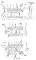
- the reactor 1 is shown schematically in FIG. In the embodiment shown here, it is formed by two electrodes 2 and 3, which are arranged vertically and area-wide from each other at a distance of a few millimeters.
- the two electrodes 2 and 3 are preferably rectangular and made of flat metal plates.
- the first electrode 2 is provided on its side facing the second electrode 2 with a dielectric layer 4, which in the exemplary embodiment shown here is made of glass.
- the two electrodes 2 and 3 are connected to a positive direct current source, one of the two electrodes 2 and 3 being connected to ground. Instead of a direct voltage or direct current source, a pulsed voltage can also be connected to the two electrodes.
- a plurality of small locally delimited, separate discharge zones 6 occurs between the two electrodes 2 and 3, in particular between the dielectric layer 4 and the second electrode 3.
- the exhaust gas 10 to be cleaned is introduced between the electrodes 2 and 3 and supplied to the discharge zones 6.
- the exhaust gas 10 to be cleaned is preferably introduced parallel to the longitudinal axis of the two electrodes 3 and 4.
- Chemical additives can be introduced into the reactor via lines 15, 16 and 17. According to the invention, such substances are introduced into the reactor which have oxidizing or reducing properties and convert the exhaust gas components NO x and / or SO 2 into usable end products by supporting the plasma.
- a suitable additive is, for example, ammonia. This allows ammonium sulfate or ammonium nitrate to be formed from the exhaust gas components.
- the reactor 1 can, if necessary, also have more than two electrodes be prepared, especially when large amounts of exhaust gas have to be cleaned.
- the invention there is the possibility of arranging a plurality of such electrodes 2 and 3 alternately with one another, so that an electrode 2 follows up and down an electrode 3, and this is followed by an electrode 2, etc.
- the electrodes 2, 3 in turn all have the same distance from one another.
- the electrodes 2 are also provided with a dielectric layer 4 on their surfaces facing the electrodes 3. A certain amount of exhaust gas can then be passed between two electrodes 2 and 3 for cleaning.
- the length of the electrodes 2 and 3 used, regardless of whether the reactor 1 consists of only two such electrodes or more, is preferably chosen between 0.1 and 1 m. If necessary, several such reactors can be connected in series to purify the exhaust gas, the exhaust gas to be cleaned being passed through the entire series connection of the reactors 1.
- the cleaned exhaust gas emerging from the reactor 1 is designated 11 here and in all other representations.
- the embodiment of the reactor shown in FIG. 2 has the same components as the embodiment shown in FIG. 1 and explained in the associated description. The same components are therefore provided with the same reference numerals. The difference is in the design of the electrode 3 and the supply of the exhaust gas.
- the elec trode 3 provided with openings 7 in some areas. These openings are arranged perpendicular to the longitudinal axis of the second electrode 3. They allow the exhaust gas to be cleaned to be fed into the area between the two electrodes 2 and 3, perpendicular to the longitudinal axis of these two electrodes. This makes it possible to introduce nitrogen gas 8 into the area between the electrodes 2 and 3 parallel to the longitudinal axis of the electrodes 2 and 3.
- atomic nitrogen can be generated from the introduced nitrogen gas 8, which is then used to reduce the nitrogen oxide contained in the exhaust gas 6.
- the mode of operation of the reactor 1 is further improved by the additional use of atomic nitrogen for the reduction of the nitrogen oxide.
- it can be used to purify exhaust gas that is loaded with large amounts of nitrogen oxide.
- the reactor 1 shown in FIG. 3 is particularly suitable for the purification of exhaust gases which, in addition to sulfur dioxide and nitrogen oxide, are additionally laden with dust.
- the reactor 1 shown in turn has two electrodes 2 and 3.
- the first electrode is formed by a metallic surface which has the same dimensions as the electrodes shown in FIGS. 1 and 2.
- the electrode 2 is coated on its side facing the second electrode 3 with a dielectric layer 4, in particular a glass layer.
- the electrode 2 is connected to a current source 5.
- the second electrode 3 is at a defined distance from this electrode 2, preferably at a distance of a few millimeters arranged that it is arranged parallel and area-wide to the first electrode 2.
- the second electrode 3 is designed as an endless belt.
- This endless belt has the same width as the electrode 2.
- the endless belt is movably supported and is guided over two 3W rollers for this purpose.
- One of the two rollers is connected to ground.
- the two rollers 3W are positioned and the dimensions of the electrode 3 are selected such that the surface of the electrode 3 facing the first electrode 2 has the same length as this.
- the surface of the electrode 3 is designed like a brush. In particular, 3 thin wires are arranged on the entire surface of the electrode so that they protrude perpendicularly from the surface.
- the exhaust gas 10 to be cleaned is introduced parallel to the longitudinal axis of the two electrodes 2 and 3 between them.
- a plurality of locally limited, separate discharge zones 6 * are formed between the two electrodes 2 and 3, the effects of which are exposed to the exhaust gas 10 to be cleaned.
- the dust contained in the exhaust gas 10 is transported due to the developing electric field to the second negatively charged electrode 3, where it is picked up by its brush-like surface.
- the electrode 3, which is designed as an endless belt, is moved continuously with the aid of the two rollers 3W, so that the dust which accumulates on the surface of the electrode 3 is constantly transported away from the area of the removal zones 6. On the rear side, the dust is then removed by washing or blowing the surface and supplied to a dust bunker 18 be passed so that the surface is then available for further use.
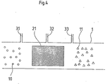
- FIG. 4 schematically shows a reactor 1, in particular its reaction zone 21.
- This reaction zone 21 can be designed, for example, as a tube and dimensioned such that it can be used as a section of an exhaust gas duct (not shown here).
- the plasma-generating arrangement is arranged within the reaction zone 21 in which the exhaust gas is cleaned. It is formed by a microwave or a high-frequency source, by an arc, spark or a so-called silent discharge arrangement. Via lines 31, 32 and 33, additives are introduced into the reaction zone which support the effect of the plasma generated.
Landscapes
- Chemical & Material Sciences (AREA)
- Engineering & Computer Science (AREA)
- Analytical Chemistry (AREA)
- General Chemical & Material Sciences (AREA)
- Oil, Petroleum & Natural Gas (AREA)
- Chemical Kinetics & Catalysis (AREA)
- Health & Medical Sciences (AREA)
- Biomedical Technology (AREA)
- Environmental & Geological Engineering (AREA)
- Treating Waste Gases (AREA)
- Exhaust Gas After Treatment (AREA)
Applications Claiming Priority (2)
| Application Number | Priority Date | Filing Date | Title |
|---|---|---|---|
| DE19843414121 DE3414121A1 (de) | 1984-04-14 | 1984-04-14 | Verfahren und vorrichtung zur reinigung von abgasen |
| DE3414121 | 1984-04-14 |
Publications (2)
| Publication Number | Publication Date |
|---|---|
| EP0158823A2 true EP0158823A2 (fr) | 1985-10-23 |
| EP0158823A3 EP0158823A3 (fr) | 1988-01-07 |
Family
ID=6233573
Family Applications (1)
| Application Number | Title | Priority Date | Filing Date |
|---|---|---|---|
| EP85102807A Withdrawn EP0158823A3 (fr) | 1984-04-14 | 1985-03-12 | Procédé et dispositif pour la purification de gaz d'échappement |
Country Status (2)
| Country | Link |
|---|---|
| EP (1) | EP0158823A3 (fr) |
| DE (1) | DE3414121A1 (fr) |
Cited By (25)
| Publication number | Priority date | Publication date | Assignee | Title |
|---|---|---|---|---|
| WO1987002909A1 (fr) * | 1985-11-08 | 1987-05-21 | The Florida State University | PROCEDE D'ELIMINATION DE SO2, NOx ET DE PARTICULES CONTENUES DANS DES MELANGES GAZEUX PAR EFFET DE COURONNE A RUISSELLEMENT |
| US4735633A (en) * | 1987-06-23 | 1988-04-05 | Chiu Kin Chung R | Method and system for vapor extraction from gases |
| EP0356684A2 (fr) * | 1988-08-01 | 1990-03-07 | Matsushita Electric Industrial Co., Ltd. | Collecteur électrostatique de poussières utilisable dans un système sous vide |
| EP0366876A1 (fr) * | 1988-10-05 | 1990-05-09 | Mitsubishi Jukogyo Kabushiki Kaisha | Appareil de traitement de gaz d'échappement |
| DE3900005A1 (de) * | 1989-01-02 | 1990-07-05 | Ruhrgas Ag | Verfahren zur verminderung von stickoxiden in abgasen |
| EP0402142A1 (fr) * | 1989-06-07 | 1990-12-12 | Satiko Okazaki | Procédé pour l'élimination de NOx de gaz d'échappement en utilisant la décharge électrique |
| EP0423384A1 (fr) * | 1989-10-16 | 1991-04-24 | Otis Elevator Company | Dispositif de commande pour un système d'élévateur sans indicateur de vitesse |
| US5125124A (en) * | 1988-08-01 | 1992-06-30 | Matsushita Electric Industrial Co., Ltd. | Electrostatic dust collector for use in vacuum system |
| WO1992020433A1 (fr) * | 1991-05-21 | 1992-11-26 | Institute Of Nuclear Chemistry And Technology | PROCEDE D'EXTRACTION DE SO2 ET DE NOx DE GAZ DE COMBUSTION ET INSTALLATION UTILISEE A CET EFFET |
| WO1995025597A1 (fr) * | 1994-03-24 | 1995-09-28 | Abb Management Ag | Procede de conditionnement des gaz perdus |
| US5468356A (en) * | 1991-08-23 | 1995-11-21 | The United States Of America As Represented By The Secretary Of The Navy | Large scale purification of contaminated air |
| WO1996037690A1 (fr) * | 1995-05-23 | 1996-11-28 | Fraunhofer-Gesellschaft zur Förderung der angewandten Forschung e.V. | Procede et dispositif pour traiter des gaz d'echappement |
| WO1997003746A1 (fr) * | 1995-07-14 | 1997-02-06 | Siemens Aktiengesellschaft | Procede et dispositif pour la decomposition et/ou destruction plasma-chimique de substances nocives |
| WO1997040265A1 (fr) * | 1996-04-23 | 1997-10-30 | Fraunhofer-Gesellschaft zur Förderung der angewandten Forschung e.V. | Procede et dispositif de traitement d'un effluent gazeux |
| US5817283A (en) * | 1996-09-06 | 1998-10-06 | Dravo Lime Company | Method for removing sulfur dioxide and nitrogen oxides from combustion gases |
| US6045618A (en) * | 1995-09-25 | 2000-04-04 | Applied Materials, Inc. | Microwave apparatus for in-situ vacuum line cleaning for substrate processing equipment |
| WO2000057992A1 (fr) * | 1999-03-25 | 2000-10-05 | Fraunhofer-Gesellschaft zur Förderung der angewandten Forschung e.V. | Dispositif et procede pour le traitement de gaz en circulation, en particulier de gaz d'echappement |
| US6187072B1 (en) | 1995-09-25 | 2001-02-13 | Applied Materials, Inc. | Method and apparatus for reducing perfluorocompound gases from substrate processing equipment emissions |
| US6194628B1 (en) | 1995-09-25 | 2001-02-27 | Applied Materials, Inc. | Method and apparatus for cleaning a vacuum line in a CVD system |
| US6193802B1 (en) | 1995-09-25 | 2001-02-27 | Applied Materials, Inc. | Parallel plate apparatus for in-situ vacuum line cleaning for substrate processing equipment |
| US6255222B1 (en) | 1999-08-24 | 2001-07-03 | Applied Materials, Inc. | Method for removing residue from substrate processing chamber exhaust line for silicon-oxygen-carbon deposition process |
| US6354241B1 (en) | 1999-07-15 | 2002-03-12 | Applied Materials, Inc. | Heated electrostatic particle trap for in-situ vacuum line cleaning of a substrated processing |
| US6576202B1 (en) | 2000-04-21 | 2003-06-10 | Kin-Chung Ray Chiu | Highly efficient compact capacitance coupled plasma reactor/generator and method |
| DE102010044252B4 (de) * | 2010-09-02 | 2014-03-27 | Reinhausen Plasma Gmbh | Vorrichtung und Verfahren zur Erzeugung einer Barriereentladung in einem Gasstrom |
| US9586178B2 (en) | 2014-04-17 | 2017-03-07 | General Electric Company | System and method for reducing nitrogen oxide in exhaust |
Families Citing this family (7)
| Publication number | Priority date | Publication date | Assignee | Title |
|---|---|---|---|---|
| DE4423397C2 (de) * | 1993-12-23 | 1999-03-11 | Fraunhofer Ges Forschung | Verfahren und Vorrichtung zur Abgasreinigung |
| DE19645689B4 (de) * | 1996-11-06 | 2006-05-11 | Bayerische Motoren Werke Ag | Vorrichtung zur Abgasnachbehandlung für eine Brennkraftmaschine, insbesondere Otto-Motor mit Magerbetrieb |
| FR2762524B1 (fr) * | 1997-04-25 | 1999-07-09 | Electricite De France | Procede de traitement d'effluents gazeux charges en composes polluants volatils par reaction desdits composes polluants avec un plasma hors equilibre thermodynamique, et reacteur dans lequel est mis en oeuvre ledit procede |
| DE10337901A1 (de) * | 2003-08-18 | 2005-03-24 | Audi Ag | Verfahren und Vorrichtung zur Synthese von Ammoniak und Verfahren zur Reinigung von Abgasen einer Brennkraftmaschine |
| DE102018214387A1 (de) * | 2018-08-24 | 2020-02-27 | Volkswagen Aktiengesellschaft | Einrichtung zum Reinigen von mit organischen Verbindungen und/oder Stoffen beladener Abluft, Verfahren zum Betreiben der Einrichtung |
| DE102018214388A1 (de) * | 2018-08-24 | 2020-02-27 | Volkswagen Aktiengesellschaft | Plasmaerzeugungseinrichtung zur Reinigung von mit organischen Verbindungen und/oder Stoffen beladener Abluft |
| DE102022119864A1 (de) | 2022-08-08 | 2024-02-08 | Manhal GbR ( vertretungsberechtigter Gesellschafter : Manhal Aogastin, 73102 Birenbach; Michael Funk, 73033 Göppingen; Margit Müller, 73084 Salach; Alexander Müller, 73072 Donzdorf; Markus Nille, 73072 Donzdorf | Filtersystem |
Citations (4)
| Publication number | Priority date | Publication date | Assignee | Title |
|---|---|---|---|---|
| DE2227949A1 (de) * | 1971-06-09 | 1973-01-04 | Monsanto Co | Verfahren zum zersetzen von stickstoffoxiden |
| JPS5310366A (en) * | 1976-07-16 | 1978-01-30 | Nippon Steel Corp | Treating method for nitrogen oxide in gas |
| DE2642751B2 (de) * | 1976-09-23 | 1978-11-30 | Cillichemie Ernst Vogelmann, 7100 Heilbronn | Vorrichtung zur Erzeugung von Ozon |
| JPS5570350A (en) * | 1978-11-17 | 1980-05-27 | Matsushita Electric Ind Co Ltd | Manufacturing method for catalyst |
-
1984
- 1984-04-14 DE DE19843414121 patent/DE3414121A1/de not_active Withdrawn
-
1985
- 1985-03-12 EP EP85102807A patent/EP0158823A3/fr not_active Withdrawn
Patent Citations (4)
| Publication number | Priority date | Publication date | Assignee | Title |
|---|---|---|---|---|
| DE2227949A1 (de) * | 1971-06-09 | 1973-01-04 | Monsanto Co | Verfahren zum zersetzen von stickstoffoxiden |
| JPS5310366A (en) * | 1976-07-16 | 1978-01-30 | Nippon Steel Corp | Treating method for nitrogen oxide in gas |
| DE2642751B2 (de) * | 1976-09-23 | 1978-11-30 | Cillichemie Ernst Vogelmann, 7100 Heilbronn | Vorrichtung zur Erzeugung von Ozon |
| JPS5570350A (en) * | 1978-11-17 | 1980-05-27 | Matsushita Electric Ind Co Ltd | Manufacturing method for catalyst |
Non-Patent Citations (2)
| Title |
|---|
| PATENT ABSTRACTS OF JAPAN, Band 4, Nr. 113 (C-21)[595], 13. August 1980; & JP-A-55 070 350 (MATSUSHITA DENKI SANGYO K.K.) 27.05.1980 * |
| PATENT ABSTRACTS, Band 2, Nr. 52 (C-78)[214], 14. April 1978; & JP-A53 010 366 (SHIN NIPPON SEITETSU) 30.01.1978 * |
Cited By (37)
| Publication number | Priority date | Publication date | Assignee | Title |
|---|---|---|---|---|
| WO1987002909A1 (fr) * | 1985-11-08 | 1987-05-21 | The Florida State University | PROCEDE D'ELIMINATION DE SO2, NOx ET DE PARTICULES CONTENUES DANS DES MELANGES GAZEUX PAR EFFET DE COURONNE A RUISSELLEMENT |
| US4735633A (en) * | 1987-06-23 | 1988-04-05 | Chiu Kin Chung R | Method and system for vapor extraction from gases |
| EP0296720A2 (fr) | 1987-06-23 | 1988-12-28 | Kin-Chung Ray Chiu | Réacteur d'extraction de plasma et son utilisation pour l'extraction de vapeur de gaz |
| US5125124A (en) * | 1988-08-01 | 1992-06-30 | Matsushita Electric Industrial Co., Ltd. | Electrostatic dust collector for use in vacuum system |
| EP0356684A2 (fr) * | 1988-08-01 | 1990-03-07 | Matsushita Electric Industrial Co., Ltd. | Collecteur électrostatique de poussières utilisable dans un système sous vide |
| EP0356684A3 (en) * | 1988-08-01 | 1990-04-04 | Matsushita Electric Industrial Co., Ltd. | Electrostatic dust collector for use in vacuum system |
| EP0366876A1 (fr) * | 1988-10-05 | 1990-05-09 | Mitsubishi Jukogyo Kabushiki Kaisha | Appareil de traitement de gaz d'échappement |
| DE3900005A1 (de) * | 1989-01-02 | 1990-07-05 | Ruhrgas Ag | Verfahren zur verminderung von stickoxiden in abgasen |
| EP0402142A1 (fr) * | 1989-06-07 | 1990-12-12 | Satiko Okazaki | Procédé pour l'élimination de NOx de gaz d'échappement en utilisant la décharge électrique |
| EP0423384A1 (fr) * | 1989-10-16 | 1991-04-24 | Otis Elevator Company | Dispositif de commande pour un système d'élévateur sans indicateur de vitesse |
| WO1992020433A1 (fr) * | 1991-05-21 | 1992-11-26 | Institute Of Nuclear Chemistry And Technology | PROCEDE D'EXTRACTION DE SO2 ET DE NOx DE GAZ DE COMBUSTION ET INSTALLATION UTILISEE A CET EFFET |
| US5468356A (en) * | 1991-08-23 | 1995-11-21 | The United States Of America As Represented By The Secretary Of The Navy | Large scale purification of contaminated air |
| US5478532A (en) * | 1991-08-23 | 1995-12-26 | The United States Of America As Represented By The Secretary Of The Navy | Large scale purification of contaminated air |
| WO1995025597A1 (fr) * | 1994-03-24 | 1995-09-28 | Abb Management Ag | Procede de conditionnement des gaz perdus |
| WO1996037690A1 (fr) * | 1995-05-23 | 1996-11-28 | Fraunhofer-Gesellschaft zur Förderung der angewandten Forschung e.V. | Procede et dispositif pour traiter des gaz d'echappement |
| WO1997003746A1 (fr) * | 1995-07-14 | 1997-02-06 | Siemens Aktiengesellschaft | Procede et dispositif pour la decomposition et/ou destruction plasma-chimique de substances nocives |
| US6517913B1 (en) | 1995-09-25 | 2003-02-11 | Applied Materials, Inc. | Method and apparatus for reducing perfluorocompound gases from substrate processing equipment emissions |
| US6193802B1 (en) | 1995-09-25 | 2001-02-27 | Applied Materials, Inc. | Parallel plate apparatus for in-situ vacuum line cleaning for substrate processing equipment |
| US6689930B1 (en) | 1995-09-25 | 2004-02-10 | Applied Materials Inc. | Method and apparatus for cleaning an exhaust line in a semiconductor processing system |
| US6045618A (en) * | 1995-09-25 | 2000-04-04 | Applied Materials, Inc. | Microwave apparatus for in-situ vacuum line cleaning for substrate processing equipment |
| US6680420B2 (en) | 1995-09-25 | 2004-01-20 | Applied Materials Inc. | Apparatus for cleaning an exhaust line in a semiconductor processing system |
| US6187072B1 (en) | 1995-09-25 | 2001-02-13 | Applied Materials, Inc. | Method and apparatus for reducing perfluorocompound gases from substrate processing equipment emissions |
| US6194628B1 (en) | 1995-09-25 | 2001-02-27 | Applied Materials, Inc. | Method and apparatus for cleaning a vacuum line in a CVD system |
| WO1997040265A1 (fr) * | 1996-04-23 | 1997-10-30 | Fraunhofer-Gesellschaft zur Förderung der angewandten Forschung e.V. | Procede et dispositif de traitement d'un effluent gazeux |
| US5827488A (en) * | 1996-09-06 | 1998-10-27 | Dravo Lime Company | Process for removing SO2 and NOx from a gaseous stream |
| US5817283A (en) * | 1996-09-06 | 1998-10-06 | Dravo Lime Company | Method for removing sulfur dioxide and nitrogen oxides from combustion gases |
| US6461409B1 (en) | 1999-03-25 | 2002-10-08 | Fraunhofer-Gesellschaft Zur Foerderung Der Angewandten Forschung E.V. | Device and method for treating flowing gases, in particular exhaust gases |
| WO2000057992A1 (fr) * | 1999-03-25 | 2000-10-05 | Fraunhofer-Gesellschaft zur Förderung der angewandten Forschung e.V. | Dispositif et procede pour le traitement de gaz en circulation, en particulier de gaz d'echappement |
| US6354241B1 (en) | 1999-07-15 | 2002-03-12 | Applied Materials, Inc. | Heated electrostatic particle trap for in-situ vacuum line cleaning of a substrated processing |
| US6255222B1 (en) | 1999-08-24 | 2001-07-03 | Applied Materials, Inc. | Method for removing residue from substrate processing chamber exhaust line for silicon-oxygen-carbon deposition process |
| US6576202B1 (en) | 2000-04-21 | 2003-06-10 | Kin-Chung Ray Chiu | Highly efficient compact capacitance coupled plasma reactor/generator and method |
| US6998027B2 (en) | 2000-04-21 | 2006-02-14 | Dryscrub, Etc | Highly efficient compact capacitance coupled plasma reactor/generator and method |
| US7241428B2 (en) | 2000-04-21 | 2007-07-10 | Dryscrub, Etc | Highly efficient compact capacitance coupled plasma reactor/generator and method |
| DE102010044252B4 (de) * | 2010-09-02 | 2014-03-27 | Reinhausen Plasma Gmbh | Vorrichtung und Verfahren zur Erzeugung einer Barriereentladung in einem Gasstrom |
| US8696996B2 (en) | 2010-09-02 | 2014-04-15 | Reinhausen Plasma Gmbh | Device and method for generating a barrier discharge in a gas flow |
| US9586178B2 (en) | 2014-04-17 | 2017-03-07 | General Electric Company | System and method for reducing nitrogen oxide in exhaust |
| GB2529502B (en) * | 2014-04-17 | 2017-09-20 | Gen Electric | Plasma assisted nitrogen oxide (NOx) abatement system |
Also Published As
| Publication number | Publication date |
|---|---|
| EP0158823A3 (fr) | 1988-01-07 |
| DE3414121A1 (de) | 1985-10-24 |
Similar Documents
| Publication | Publication Date | Title |
|---|---|---|
| EP0158823A2 (fr) | Procédé et dispositif pour la purification de gaz d'échappement | |
| DE3234100C2 (de) | Plasmalichtbogeneinrichtung zum Auftragen von Überzügen | |
| EP1902156B1 (fr) | Procede de traitement plasma et/ou de revetement plasma en pression atmospherique continue de pieces d'usinage | |
| DE2810735C2 (de) | Elektrische Gasreinigungsvorrichtung | |
| DE3403726C2 (fr) | ||
| DE2727973C2 (de) | Verfahren zum Abscheiden hochohmiger Stäube aus Gasen | |
| DE112011102207B4 (de) | Zuführvorrichtung für reaktive Spezies und Oberflächenbehandlungseinrichtung | |
| DE112011102192B4 (de) | Zuführvorrichtung für reaktive Spezies und Oberflächenbehandlungseinrichtung | |
| DE2133173B2 (de) | Verfahren und Vorrichtung zum Abbeizen eines oxydierten Blechbandes | |
| DE4017120A1 (de) | Ueberbrueckungsstrom-koronaentladungsgenerator | |
| DE2419265A1 (de) | Staubladevorrichtung fuer ein elektrisches entstaubungsgeraet | |
| DE4413118A1 (de) | Gasreinigungsvorrichtung | |
| CH673237A5 (fr) | ||
| DE2462539A1 (de) | Elektrische staubsammelvorrichtung | |
| EP0402798A2 (fr) | Dispositif de revêtement | |
| DE3608291A1 (de) | Verfahren zur selektiven oder simultanen abscheidung von schadstoffen aus rauchgasen durch bestrahlung der rauchgase mit elektronenstrahlen | |
| DE2639359A1 (de) | Einrichtung zur elektrostatischen schwebstoffabscheidung | |
| DE2701640A1 (de) | Verbesserte vorrichtung zur aufrechterhaltung einer vorbestimmten elektrisch geladenen atmosphaere | |
| WO1997014546A1 (fr) | Dispositif de traitement de substrats plats avec une station a decharges corona | |
| DE2146539C3 (de) | Vorrichtung zum homogenen Auf· oder Entladen der Oberfläche von elektrofotografischen Aufzeichnungsmaterialien | |
| DE19913614C1 (de) | Vorrichtung und Verfahren zur Behandlung von strömenden Gasen, insbesondere von Abgasen | |
| DE69723699T2 (de) | Verfahren zum Reinigen eines Substrats und Vorrichtung zur Durchführung des Verfahrens | |
| DE2341541C2 (de) | Elektroabscheider | |
| DE19524214A1 (de) | Elektrofilter | |
| DE1597897B2 (de) | Verfahren und vorrichtung zum gleichfoermigen negativen aufladen einer flaeche mittels einer koronaentladung |
Legal Events
| Date | Code | Title | Description |
|---|---|---|---|
| PUAI | Public reference made under article 153(3) epc to a published international application that has entered the european phase |
Free format text: ORIGINAL CODE: 0009012 |
|
| AK | Designated contracting states |
Designated state(s): BE FR GB NL |
|
| PUAL | Search report despatched |
Free format text: ORIGINAL CODE: 0009013 |
|
| AK | Designated contracting states |
Kind code of ref document: A3 Designated state(s): BE FR GB NL |
|
| STAA | Information on the status of an ep patent application or granted ep patent |
Free format text: STATUS: THE APPLICATION IS DEEMED TO BE WITHDRAWN |
|
| 18D | Application deemed to be withdrawn |
Effective date: 19880401 |
|
| RIN1 | Information on inventor provided before grant (corrected) |
Inventor name: SCHMIDT, CONRAD, DR. DIPL.-PHYS. |