EP0157857B1 - Vorrichtung zur gleichmässigen dosierung, verteilung und aufbringung von flüssig formulierten schutzstoffen, insbesondere beizmitteln - Google Patents
Vorrichtung zur gleichmässigen dosierung, verteilung und aufbringung von flüssig formulierten schutzstoffen, insbesondere beizmitteln Download PDFInfo
- Publication number
- EP0157857B1 EP0157857B1 EP84903709A EP84903709A EP0157857B1 EP 0157857 B1 EP0157857 B1 EP 0157857B1 EP 84903709 A EP84903709 A EP 84903709A EP 84903709 A EP84903709 A EP 84903709A EP 0157857 B1 EP0157857 B1 EP 0157857B1
- Authority
- EP
- European Patent Office
- Prior art keywords
- outlet
- liquid
- mixing drum
- compressed air
- liquid pipe
- Prior art date
- Legal status (The legal status is an assumption and is not a legal conclusion. Google has not performed a legal analysis and makes no representation as to the accuracy of the status listed.)
- Expired
Links
- 239000007788 liquid Substances 0.000 title claims abstract description 38
- 230000001681 protective effect Effects 0.000 title claims abstract description 14
- 239000003153 chemical reaction reagent Substances 0.000 title abstract 2
- 239000000126 substance Substances 0.000 claims description 13
- 239000007921 spray Substances 0.000 claims description 11
- 238000005554 pickling Methods 0.000 description 5
- 239000003795 chemical substances by application Substances 0.000 description 4
- 239000003595 mist Substances 0.000 description 4
- 238000002360 preparation method Methods 0.000 description 3
- 238000000889 atomisation Methods 0.000 description 2
- 239000012669 liquid formulation Substances 0.000 description 2
- QSHDDOUJBYECFT-UHFFFAOYSA-N mercury Chemical compound [Hg] QSHDDOUJBYECFT-UHFFFAOYSA-N 0.000 description 2
- 229910052753 mercury Inorganic materials 0.000 description 2
- 230000001105 regulatory effect Effects 0.000 description 2
- 239000002689 soil Substances 0.000 description 2
- 238000005299 abrasion Methods 0.000 description 1
- 230000015572 biosynthetic process Effects 0.000 description 1
- 230000003749 cleanliness Effects 0.000 description 1
- 238000006073 displacement reaction Methods 0.000 description 1
- 230000000694 effects Effects 0.000 description 1
- 239000000834 fixative Substances 0.000 description 1
- 238000009472 formulation Methods 0.000 description 1
- 239000000463 material Substances 0.000 description 1
- 238000000034 method Methods 0.000 description 1
- 239000000203 mixture Substances 0.000 description 1
- 239000012071 phase Substances 0.000 description 1
- 239000012808 vapor phase Substances 0.000 description 1
Images

Classifications
-
- A—HUMAN NECESSITIES
- A23—FOODS OR FOODSTUFFS; TREATMENT THEREOF, NOT COVERED BY OTHER CLASSES
- A23B—PRESERVATION OF FOODS, FOODSTUFFS OR NON-ALCOHOLIC BEVERAGES; CHEMICAL RIPENING OF FRUIT OR VEGETABLES
- A23B9/00—Preservation of edible seeds, e.g. cereals
- A23B9/14—Coating with a protective layer; Compositions or apparatus therefor
-
- A—HUMAN NECESSITIES
- A01—AGRICULTURE; FORESTRY; ANIMAL HUSBANDRY; HUNTING; TRAPPING; FISHING
- A01C—PLANTING; SOWING; FERTILISING
- A01C1/00—Apparatus, or methods of use thereof, for testing or treating seed, roots, or the like, prior to sowing or planting
- A01C1/08—Immunising seed
-
- B—PERFORMING OPERATIONS; TRANSPORTING
- B05—SPRAYING OR ATOMISING IN GENERAL; APPLYING FLUENT MATERIALS TO SURFACES, IN GENERAL
- B05B—SPRAYING APPARATUS; ATOMISING APPARATUS; NOZZLES
- B05B1/00—Nozzles, spray heads or other outlets, with or without auxiliary devices such as valves, heating means
- B05B1/26—Nozzles, spray heads or other outlets, with or without auxiliary devices such as valves, heating means with means for mechanically breaking-up or deflecting the jet after discharge, e.g. with fixed deflectors; Breaking-up the discharged liquid or other fluent material by impinging jets
- B05B1/262—Nozzles, spray heads or other outlets, with or without auxiliary devices such as valves, heating means with means for mechanically breaking-up or deflecting the jet after discharge, e.g. with fixed deflectors; Breaking-up the discharged liquid or other fluent material by impinging jets with fixed deflectors
- B05B1/265—Nozzles, spray heads or other outlets, with or without auxiliary devices such as valves, heating means with means for mechanically breaking-up or deflecting the jet after discharge, e.g. with fixed deflectors; Breaking-up the discharged liquid or other fluent material by impinging jets with fixed deflectors the liquid or other fluent material being symmetrically deflected about the axis of the nozzle
-
- B—PERFORMING OPERATIONS; TRANSPORTING
- B05—SPRAYING OR ATOMISING IN GENERAL; APPLYING FLUENT MATERIALS TO SURFACES, IN GENERAL
- B05B—SPRAYING APPARATUS; ATOMISING APPARATUS; NOZZLES
- B05B7/00—Spraying apparatus for discharge of liquids or other fluent materials from two or more sources, e.g. of liquid and air, of powder and gas
- B05B7/02—Spray pistols; Apparatus for discharge
- B05B7/06—Spray pistols; Apparatus for discharge with at least one outlet orifice surrounding another approximately in the same plane
- B05B7/062—Spray pistols; Apparatus for discharge with at least one outlet orifice surrounding another approximately in the same plane with only one liquid outlet and at least one gas outlet
- B05B7/066—Spray pistols; Apparatus for discharge with at least one outlet orifice surrounding another approximately in the same plane with only one liquid outlet and at least one gas outlet with an inner liquid outlet surrounded by at least one annular gas outlet
-
- B—PERFORMING OPERATIONS; TRANSPORTING
- B05—SPRAYING OR ATOMISING IN GENERAL; APPLYING FLUENT MATERIALS TO SURFACES, IN GENERAL
- B05B—SPRAYING APPARATUS; ATOMISING APPARATUS; NOZZLES
- B05B7/00—Spraying apparatus for discharge of liquids or other fluent materials from two or more sources, e.g. of liquid and air, of powder and gas
- B05B7/02—Spray pistols; Apparatus for discharge
- B05B7/06—Spray pistols; Apparatus for discharge with at least one outlet orifice surrounding another approximately in the same plane
- B05B7/062—Spray pistols; Apparatus for discharge with at least one outlet orifice surrounding another approximately in the same plane with only one liquid outlet and at least one gas outlet
- B05B7/066—Spray pistols; Apparatus for discharge with at least one outlet orifice surrounding another approximately in the same plane with only one liquid outlet and at least one gas outlet with an inner liquid outlet surrounded by at least one annular gas outlet
- B05B7/067—Spray pistols; Apparatus for discharge with at least one outlet orifice surrounding another approximately in the same plane with only one liquid outlet and at least one gas outlet with an inner liquid outlet surrounded by at least one annular gas outlet the liquid outlet being annular
Definitions
- the invention relates to a device for uniformly metering, distributing and applying liquid-formulated protective substances, in particular mordants, to seeds, with a mixing drum with a seed inlet and feed line for the protective substances.
- aqueous mordants has improved to a small extent the burden on people working with the mordant, but since the application rates are not reduced for functional safety reasons, the excessive pollution of the environment remains.
- the application of the mordant in a manner that is uniformly distributed all over the surface of the seeds is also a prerequisite for keeping the application rates as small as possible.
- Liquid formulations of seed dressings consist in essence of a sticky carrier in which the substance active for dressing is distributed.
- Conventional spray devices are easily clogged by the carrier substance necessary for the mordant to adhere to the surface of the seeds and thus become inoperable. They are therefore unsuitable for applying liquid mordants.
- the aim of the invention is to provide an operationally reliable device with which all liquid formulated pickling agents can be converted into a spray mist in order to achieve an optimal all-round distribution with the lowest application rates.
- the liquid pipeline coming from a metering pump and opening into a mixing drum and serving as a supply line for the protective substances is connected to a compensating vessel or pipe for secondary air intake and into the mixing drum opening compressed air line is provided, in the outlet of which the outlet of the liquid pipe is concentric and a baffle plate is arranged opposite the outlet of the liquid pipe.
- Secondary air is continuously sucked in through the expansion vessel or tube due to the negative pressure at the end of the liquid tube and mixed with the pickling agent; After the metering pump is switched off, the secondary air causes the liquid pipeline to be sucked empty without dripping.
- the secondary air empties the liquid pipe 100% without droplet formation, which simplifies keeping it clean and ensures exact dosing.
- Dosing is carried out by recording the weight of the material entering the mixing drum and inevitable impulse commands to the dosing pump.
- the metering pump sucks the specified amounts of mordant liquid from a container provided with an agitator and presses it into the tubular nozzle system according to the invention.
- compressed air - which is regulated by a pressure control manometer - a negative pressure is generated at the end of the pipe, which means that the liquid line is under permanent negative pressure. Due to the negative pressure generated in the liquid pipe, air is continuously sucked in through the compensating pipe built into the liquid line and mixed with the mordant liquid.
- the distance of the baffle plate from the outlet of the liquid pipeline can be changed.
- a cylinder body is preferably attached to the side of the baffle plate facing away from the outlet of the liquid pipeline.
- the baffle plate preferably provided with a cylinder body, which is attached at a certain and adjustable distance from the liquid pipe outlet, performs the following tasks:
- the disk diameter of the baffle disk and, if applicable, the cylinder body determine the scatter of the spray mist generated.
- the different amounts of seed dressing to be applied per kg of seed require the compressed air and secondary air quantities required for atomization to be changed by means of air pressure control.
- the compressed air pressure is increased, the distance of the baffle plate from the end of the liquid pipe must be changed at the same time, so that a negative pressure is built up in the liquid pipe, which causes secondary air to be sucked in.
- both the negative pressure in the liquid pipe and the atomization angle of the spray can be regulated.
- the shape of the spray mist can be changed from spherical to conical by means of baffle plates with different diameters and / or shapes and by bodies attached to the baffle plates.
- the compressed air line is designed as an expansion cylinder immediately before its exit end.
- the expansion cylinder is used for even pressure distribution at the outlet of the compressed air line.
- the baffle can, for. B. in an adjustable bracket or with a guided in the liquid pipeline pin at a distance from the outlet of the pipeline.
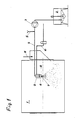
- Fig. 1 shows a schematic representation of a device according to the invention
- Fig. 2 shows the actual device for applying a pickling agent in an enlarged view
- Fig. 3 shows an embodiment.
- a metering pump 3 for. B. a diaphragm pump, 2 pickling agent removed from a mixer and sprayed via the liquid pipe 4 in the mixing drum 1.
- the seed to be treated enters the mixing drum 1 via the inlet 11.
- a compensating pipe 5 is connected to the liquid pipeline 4, through which secondary air can be drawn in and also has the purpose of compensating for pressure differences in the liquid pipeline originating from the metering pump.
- a compressed air line 10 is provided for the supply of compressed air, the outlet of which concentrically surrounds the outlet 6 of the liquid pipeline 4, so that an annular gap 13 is formed for the outlet of the compressed air.
- the compressed air line 10 is designed as an expansion cylinder 9 (see FIGS. 2 and 3).
- a baffle plate 7 with a cylinder body 8 is arranged opposite and at a distance from the outlet 6 of the liquid pipeline 4.
- the baffle plate 7 is held in an adjustable bracket 12 or a pin 14.
- the cylinder body 8 has the task of determining the shape of the spray pattern.
- the edge vertebrae that are detached are passed on by the baffle plate 7 to the cylinder body 8, so that an elongated spray pattern is produced.
- the length of the cylinder body 8 therefore determines the length of the spray pattern.
- the width of the spray pattern is determined by the diameter of the baffle plate 7.
Landscapes
- Life Sciences & Earth Sciences (AREA)
- Engineering & Computer Science (AREA)
- Soil Sciences (AREA)
- Environmental Sciences (AREA)
- Wood Science & Technology (AREA)
- Zoology (AREA)
- Chemical & Material Sciences (AREA)
- Food Science & Technology (AREA)
- Polymers & Plastics (AREA)
- Nozzles (AREA)
- Pretreatment Of Seeds And Plants (AREA)
Description
- Die Erfindung betrifft eine Vorrichtung zur gleichmäßigen Dosierung, Verteilung und Aufbringung von flüssig formulierten Schutzstoffen, insbesondere Beizmitteln, auf Samen, mit einer Mischtrommel mit Sameneinlauf und Zuleitung für die Schutzstoffe.
- Es ist bekannt, pulverförmige Schutzstoffe auf Samenkörner aufzubringen, wobei die Körner mit den Schutzstoffen in einer Mischtrommel miteinander vermengt werden. Diese bekannte Aufbringungsart (Beizung) mit pulverförmigen Stoffen hat den Nachteil, daß durch den Abrieb bis zu 50 % der Schutzstoffe verloren gehen, bevor der Samen in den Boden gelangt. Man muß daher überdosieren, um die notwendigen Mengen zum Schutz des Samens in den Boden zu bringen. Die Überdosierung belastet einerseits die Gesundheit der mit der Beizung beschäftigten Menschen und anderseits natürlich auch die Umwelt.
- Durch die Formulierung von wässerigen Beizmitteln wurde zu einem geringen Maß eine Verbesserung hinsichtlich der Belastung der mit der Beizung beschäftigten Menschen erreicht, da aber aus Funktions-Sicherheitsgründen die Aufwandmengen nicht reduziert werden, bleibt die übermäßige Belastung der Umwelt bestehen.
- Solange Quecksilberpräparate als Beizmittel für Saatgut verwendet wurden, war eine genaue Verteilung der Schutzstoffe über die Samenoberfläche nicht notwendig, da diese Präparate eine Dampfphase bildeten, die das zu beizende Saatgut durchdrang und dabei seine Wirkung entfaltete.
- Durch die Verdrängung der Quecksilberpräparate durch andere Mittel, die keine Gasphase bilden, wurde es erforderlich, die Beizmittel gleichmäßig über die Samenkörneroberfläche rundum verteilt aufzubringen.
- Das Aufbringen der Beizmittel in über die Samenkörneroberfläche rundum gleichmäßig verteilter Weise ist auch die Voraussetzung dafür, daß die Aufwandmengen so klein wie möglich gehalten werden können.
- Der Versuch, flüssige Formulierungen von Beizmitteln mit bekannten Sprüheinrichtungen auf das Saatgut aufzubringen, scheitert an der Konsistenz solcher Beizmittel. Flüssige Formulierungen von Beizmittel für Saatgut bestehen nämlich im Wesen aus einem klebrigen Trägerstoff in dem die für die Beizung wirksame Substanz verteilt ist. Übliche Sprüheinrichtungen werden durch den für die Haftung des Beizmittels auf der Samenkörneroberfläche notwendigen Trägerstoff leicht verstopft und somit funktionsuntüchtig. Sie sind daher zur Aufbringung flüssiger Beizmittel untauglich.
- Ziel der Erfindung ist die Bereitstellung einer betriebssicheren Vorrichtung, mit der alle flüssig formulierten Beizmittel in einen Sprühnebel übergeführt werden können, um bei geringsten Aufwandmengen eine optimale Rundumverteilung zu erreichen.
- Dieses Ziel wird mit einer Vorrichtung der eingangs genannten Art erreicht, bei der erfindungsgemäß die von einer Dosierpumpe kommende und in eine Mischtrommel mündende, als Zuleitung für die Schutzstoffe dienende Flüssigkeitsrohrleitung mit einem Ausgleichsgefäß oder -rohr zur Sekundärluftansaugung in Verbindung steht, und ein in die Mischtrommel mündende Druckluftleitung vorgesehen ist, in deren Ausgang konzentrisch der Ausgang der Flüssigkeitsrohrleitung liegt und gegenüber dem Ausgang der Flüssigkeitsrohrleitung eine Prallplatte angeordnet ist. Durch das Ausgleichsgefäß bzw. -rohr wird durch den Unterdruck am Flüssigkeitsrohrende kontinuierlich Sekundärluft angesaugt und mit dem Beizmittel vermischt ; nach Abschalten der Dosierpumpe bewirkt die Sekundärluft, daß die Flüssigkeitsrohrleitung ohne Nachtropfen leergesaugt wird. Durch die Sekundärluft erfolgt eine 100%ige Entleerung des Flüssigkeitsrohres ohne Tropfenbildung, wodurch die Reinhaltung vereinfacht wird und die exakte Dosierung gewährleistet ist.
- Mit der erfindungsgemäßen Vorrichtung ist es möglich, jede gewünschte Aufwandmenge an Beizmittelflüssigkeiten mit verschiedenen Viskositätswerten optimal in einem geschlossenen System aufbringen zu können, wobei die Erfüllung aller Anforderungen hinsichtlich der Betriebssicherheit, der Reinhaltung und der Hygienevorschriften gewährleistet ist.
- Die Dosierung erfolgt durch gewichtsmäßige Erfassung des in die Mischtrommel einlaufenden Gutes und zwangsläufige Impulsbefehle an die Dosierpumpe.
- Die Dosierpumpe saugt aus einem mit einem Rührwerk versehenen Behälter die vorgegebenen Mengen an Beizmittelflüssigkeit und drückt sie in das erfindungsgemäße Rohrdüsensystem. Mittels Preßluft - die durch einen Druckregelmanometer geregelt wird -wird am Rohrende ein Unterdruck erzeugt, wodurch die Flüssigkeitsleitung unter permanentem Unterdruck steht. Durch den erzeugten Unterdruck im Flüssigkeitsrohr wird durch das in die Flüssigkeitsleitung eingebaute Ausgleichsrohr kontinuierlich Luft angesaugt und mit der Beizmittelflüssigkeit vermischt.
- Nach einem weiteren Merkmal der Erfindung ist der Abstand der Prallscheibe vom Ausgang der Flüssigkeitsrohrleitung veränderbar.
- Vorzugsweise ist an der vom Ausgang der Flüssigkeitsrohrleitung abgewandten Seite der Prallscheibe ein Zylinderkörper angebracht.
- Die in einem bestimmten und verstellbaren Abstand von dem Flüssigkeitsrohrausgang angebrachte, vorzugsweise mit einem Zylinderkörper versehene Prallscheibe erfüllt folgende Aufgaben :
- Sie bewirkt die optimale Vermischung der mit hoher Geschwindigkeit austretenden Beizflüssigkeit mit Sekundärluft sowie auch mit der ebenfalls austretenden Preßluft zu einem Nebel innerhalb der Mischtrommel. Der Scheibendurchmesser der Prallscheibe sowie gegebenenfalls der Zylinderkörper bestimmen hiebei die Streuung des erzeugten Sprühnebels.
- Die pro kg Saatgut aufzubringenden verschiedenen Beizmittelmengen erfordern die Änderung der zur Vernebelung notwendigen Preßluft- und Sekundärluftmengen durch Luftdruckregelung. Bei Erhöhung des Preßluftdruckes muß gleichzeitig der Abstand der Prallscheibe.vom Flüssigkeitsrohrende verändert werden, damit im Flüssigkeitsrohr ein Unterdruck aufgebaut wird, der das Ansaugen von Sekundärluft bewirkt.
- Durch die Veränderung des Abstandes der Prallscheibe vom Ausgang der Flüssigkeitsrohrleitung kann also sowohl der Unterdruck in der Flüssigkeitsrohrleitung als auch der Zerstäubungswinkel des Sprühnebels reguliert werden.
- Durch Prallscheiben mit verschiedenen Durchmessern und/oder Formen sowie durch an den Prallscheiben angebrachten Körpern kann die Sprühnebelform von kugelig bis kegelig verändert werden.
- Nach einem weiteren Merkmal der Erfindung ist die Druckluftleitung unmittelbar vor ihrem Austrittsende als Expansionszylinder ausgebildet. Der Expansionszylinder dient der gleichmäßigen Druckverteilung am Ausgang der Druckluftleitung.
- Die Prallscheibe kann z. B. in einem verstellbaren Bügel oder mit einem in der Flüssigkeitsrohrleitung geführten Stift im Abstand vom Ausgang der Rohrleitung gehalten sein.
- Im folgenden wird eine Ausführungsform der Erfindung an Hand der Zeichnung näher erläutert.
- Fig. 1 zeigt eine schematische Darstellung einer erfindungsgemäßen Vorrichtung, Fig. 2 die eigentliche Einrichtung zum Aufbringen eines Beizmittels in vergrößerter Darstellung und Fig. 3 eine Ausführungsvariante.
- Wie aus Fig. 1 ersichtlich, wird mittels- einer Dosierpumpe 3, z. B. einer Membranpumpe, aus einem Mischer 2 Beizmittel entnommen und über die Flüssigkeitsrohrleitung 4 in der Mischtrommel 1 versprüht. Der zu behandelnde Samen gelangt über den Einlauf 11 in die Mischtrommel 1. Mit der Flüssigkeitsrohrleitung 4 steht ein Ausgleichsrohr 5 in Verbindung, durch das Sekundärluft angesaugt werden kann und außerdem den Zweck hat, von der Dosierpumpe herrührende Druckunterschiede in der Flüssigkeitsrohrleitung auszugleichen. Für die Zufuhr von Druckluft ist eine Druckluftleitung 10 vorgesehen, deren Ausgang den Ausgang 6 der Flüssigkeitsrohrleitung 4 konzentrisch umgibt, so daß ein Ringspalt 13 für den Austritt der Druckluft gebildet ist. Unmittelbar vor ihrem Ausgang ist die Druckluftleitung 10 als Expansionszylinder 9 ausgebildet (siehe Fig. 2 und 3). Gegenüber dem Ausgang 6 der Flüssigkeitsrohrleitung 4 und im Abstand von diesem ist eine Prallscheibe 7 mit einem Zylinderkörper 8 angeordnet. Die Prallscheibe 7 ist in einem verstellbaren Bügel 12 oder einem Stift 14 gehalten. Der Zylinderkörper 8 hat die Aufgabe, die Form des Sprühbildes zu bestimmen. Die sich ablösenden Randwirbeln werden von der Prallscheibe 7 auf den Zylinderkörper 8 weitergeleitet, so daß ein längliches Sprühbild entsteht. Die Länge des Zylinderkörpers 8 bestimmt daher die Länge des Sprühbildes. Die Breite des Sprühbildes wird durch den Durchmesser der Prallscheibe 7 festgelegt.
Claims (4)
Applications Claiming Priority (2)
| Application Number | Priority Date | Filing Date | Title |
|---|---|---|---|
| AT0356683A AT378462B (de) | 1983-10-07 | 1983-10-07 | Vorrichtung zur gleichmaessigen dosierung, verteilung und aufbringung von fluessig formulierten schutzstoffen, insbesondere beizmitteln |
| AT3566/83 | 1983-10-07 |
Publications (2)
| Publication Number | Publication Date |
|---|---|
| EP0157857A1 EP0157857A1 (de) | 1985-10-16 |
| EP0157857B1 true EP0157857B1 (de) | 1988-04-13 |
Family
ID=3552295
Family Applications (1)
| Application Number | Title | Priority Date | Filing Date |
|---|---|---|---|
| EP84903709A Expired EP0157857B1 (de) | 1983-10-07 | 1984-10-05 | Vorrichtung zur gleichmässigen dosierung, verteilung und aufbringung von flüssig formulierten schutzstoffen, insbesondere beizmitteln |
Country Status (10)
| Country | Link |
|---|---|
| US (1) | US4658754A (de) |
| EP (1) | EP0157857B1 (de) |
| JP (1) | JPS61500101A (de) |
| AT (1) | AT378462B (de) |
| CS (1) | CS261876B2 (de) |
| DD (1) | DD227602A5 (de) |
| DE (1) | DE3470369D1 (de) |
| DK (1) | DK157163C (de) |
| SU (1) | SU1403984A3 (de) |
| WO (1) | WO1985001636A1 (de) |
Families Citing this family (12)
| Publication number | Priority date | Publication date | Assignee | Title |
|---|---|---|---|---|
| FR2603154B1 (fr) * | 1986-09-02 | 1989-06-30 | Ceres | Procede de pelliculage des semences |
| FR2618041B1 (fr) * | 1987-07-16 | 1991-06-21 | Ceres Ets | Dispositif pour le traitement des semences |
| US5495418A (en) * | 1993-06-18 | 1996-02-27 | Latini Machine Company | Automatic panning system |
| DE4417555A1 (de) * | 1994-05-19 | 1995-11-23 | Bayer Ag | Verwendung von Gelformulierungen als Beizmittel |
| US5453383A (en) * | 1994-06-14 | 1995-09-26 | General Mills, Inc. | Method of applying sugar coating by using steam assisted discharge nozzle |
| DE19514326C2 (de) * | 1995-04-18 | 1998-04-02 | Wolfgang Peltzer | Vorrichtung zum Einblasen von teilchenförmigen Dämmstoffen |
| IT1309484B1 (it) * | 1999-04-29 | 2002-01-23 | Genio Migliorati | Ugello micronizzatore di acqua ad impatto, per abbattimento polveri. |
| US20110081415A1 (en) * | 2005-03-10 | 2011-04-07 | Taisho Pharmaceutical Co., Ltd | Coating apparatus |
| ES2311342B1 (es) * | 2006-04-24 | 2009-10-23 | San Alf Quimicas S.A. | Procedimiento para la desinfeccion de frutas y hortalizas y dispositivo para la puesta en practica del mismo. |
| CN102470386A (zh) * | 2009-08-11 | 2012-05-23 | 积水医疗株式会社 | 涂敷装置及液态物的涂敷方法 |
| JP6664875B2 (ja) * | 2015-01-06 | 2020-03-13 | 日本車輌製造株式会社 | 自動種子消毒装置 |
| CN112715092A (zh) * | 2020-12-10 | 2021-04-30 | 中国农业科学院兰州畜牧与兽药研究所 | 一种农业牧草种子拌种装置及其使用方法 |
Family Cites Families (11)
| Publication number | Priority date | Publication date | Assignee | Title |
|---|---|---|---|---|
| US696057A (en) * | 1901-03-16 | 1902-03-25 | Christian E Lanstrum | Spraying device. |
| FR1009980A (fr) * | 1948-07-19 | 1952-06-05 | Appareillage pour la mise en oeuvre du procédé électrostatique pour répandre les produits de protection des cultures | |
| US3084874A (en) * | 1959-08-12 | 1963-04-09 | Aeroprojects Inc | Method and apparatus for generating aerosols |
| US3138482A (en) * | 1961-09-14 | 1964-06-23 | American Cyanamid Co | Peanut flocontrol sprayer |
| FR1337299A (fr) * | 1962-06-28 | 1963-09-13 | Appareil pour détruire les insectes dans les grains ou les graines | |
| US3253944A (en) * | 1964-01-13 | 1966-05-31 | Wisconsin Alumni Res Found | Particle coating process |
| AU417671B2 (en) * | 1967-07-17 | 1971-10-08 | Ministerstvo Zemedelstvt A Vyzivy | Method and equipment for anaerobic seed dressing |
| GB1237144A (en) * | 1968-07-26 | 1971-06-30 | Pfizer Ltd | Coating method |
| US3903333A (en) * | 1973-03-30 | 1975-09-02 | Tennessee Valley Authority | Production of slow release nitrogen fertilizers by improved method of coating urea with sulfur |
| SU745405A1 (ru) * | 1979-02-27 | 1980-07-07 | Проектно-Технологический Институт "Сельхозтехпроект" | Устройство дл жидкостной обработки корнеклубнеплодов |
| US4249343A (en) * | 1979-07-25 | 1981-02-10 | Eastman Kodak Company | Seed coatings |
-
1983
- 1983-10-07 AT AT0356683A patent/AT378462B/de not_active IP Right Cessation
-
1984
- 1984-10-05 WO PCT/AT1984/000033 patent/WO1985001636A1/de not_active Ceased
- 1984-10-05 EP EP84903709A patent/EP0157857B1/de not_active Expired
- 1984-10-05 JP JP59503714A patent/JPS61500101A/ja active Pending
- 1984-10-05 DE DE8484903709T patent/DE3470369D1/de not_active Expired
- 1984-10-05 US US06/744,006 patent/US4658754A/en not_active Expired - Fee Related
- 1984-10-08 CS CS847595A patent/CS261876B2/cs unknown
- 1984-10-08 DD DD84268152A patent/DD227602A5/de not_active IP Right Cessation
-
1985
- 1985-05-23 DK DK229485A patent/DK157163C/da not_active IP Right Cessation
- 1985-05-31 SU SU853901148A patent/SU1403984A3/ru active
Also Published As
| Publication number | Publication date |
|---|---|
| WO1985001636A1 (fr) | 1985-04-25 |
| JPS61500101A (ja) | 1986-01-23 |
| DD227602A5 (de) | 1985-09-25 |
| US4658754A (en) | 1987-04-21 |
| AT378462B (de) | 1985-08-12 |
| DK229485A (da) | 1985-05-23 |
| CS759584A2 (en) | 1988-06-15 |
| ATA356683A (de) | 1985-01-15 |
| DK229485D0 (da) | 1985-05-23 |
| CS261876B2 (en) | 1989-02-10 |
| SU1403984A3 (ru) | 1988-06-15 |
| DK157163B (da) | 1989-11-20 |
| EP0157857A1 (de) | 1985-10-16 |
| DK157163C (da) | 1990-04-16 |
| DE3470369D1 (en) | 1988-05-19 |
Similar Documents
| Publication | Publication Date | Title |
|---|---|---|
| DE60119637T2 (de) | Zerstäubungsanordnung insbesondere für die landwirtschaftliche Verwendung | |
| EP0076472B1 (de) | Vorrichtung zum gleichmässigen Verteilen eines Schüttgutstroms | |
| DE204437T1 (de) | Pulverspritzpistolen. | |
| DE3904759C2 (de) | ||
| DE1009071B (de) | Pistole zum Aufspritzen von mindestens zwei Spritzstoffen mit einem zusaetzlichen, auswechselbaren Spritzstoffbehaelter | |
| WO1985001636A1 (fr) | Installation pour le dosage, la repartition et l'epandage reguliers d'elements protecteurs sous forme liquide, en particulier d'agents mordants | |
| EP3645170A1 (de) | Abgabeeinheit zur abgabe einer endflüssigkeit mit einem definierten endmischverhältnis | |
| EP0432673B1 (de) | Fahrbare Vorrichtung zum Herstellen einer insbesondere zum Versprühen bestimmten, aus Wasser und mindestens einem flüssigen Wirkstoff bestehenden Lösung | |
| CH516050A (de) | Fahrbare Streuvorrichtung, insbesondere zum Streuen von Salz auf Fahr- oder Gehbahnen | |
| DE3143910A1 (de) | Geraet zum verteilen von guelle | |
| DE102017214783A1 (de) | Landwirtschaftliche Abgabeeinheit zur Abgabe einer Flüssigkeit | |
| DE2054222B1 (de) | Vorrichtung zum Besprühen von Pflanzen | |
| DE19509223C1 (de) | Mehrstoff-Zerstäuberdüse | |
| DE102020128773A1 (de) | Landwirtschaftliche Feldspritze und Spritzvorrichtung für eine landwirtschaftliche Feldspritze | |
| DE69430247T2 (de) | In-line injektionssystem von teilchenförmigen zusammensetzungen in sprüheinrichtungen | |
| DE929221C (de) | Verfahren und Vorrichtung zur Feinstverteilung von Fluessigkeiten | |
| DE887127C (de) | Verfahren und Vorrichtung zur Feinstverteilung von Fluessigkeiten | |
| DE3007990A1 (de) | Verfahren und vorrichtung zum einduesen fluessiger zusaetze in das in einem mischer oder mischgranulator bewegte schuettgut | |
| EP3991554B1 (de) | Landwirtschaftliche feldspritze und spritzvorrichtung für eine landwirtschaftliche feldspritze | |
| DE19749033B4 (de) | Verfahren und Vorrichtung zum gleichmäßigen Fördern und Abgeben von Pulver an einen laufenden Bandstreifen | |
| DE2103362A1 (de) | Vorrichtung zum Mischen verschiedenartiger Flüssigkeiten | |
| EP0210282A1 (de) | Vorrichtung zum dosierten Zuteilen verschiedener Komponenten und/oder dosierten Aufteilen bzw. Ausbringen flüssiger oder pastöser Stoffe | |
| DE2535089A1 (de) | Vorrichtung zum zerstaeuben von fluessigkeiten und verwendung dieser vorrichtung | |
| DE1235653B (de) | Duese fuer Feldspruehrohre von Pflanzenschutzgeraeten | |
| DE3623661A1 (de) | Landwirtschaftliche geraetekombination |
Legal Events
| Date | Code | Title | Description |
|---|---|---|---|
| PUAI | Public reference made under article 153(3) epc to a published international application that has entered the european phase |
Free format text: ORIGINAL CODE: 0009012 |
|
| 17P | Request for examination filed |
Effective date: 19850531 |
|
| AK | Designated contracting states |
Designated state(s): CH DE FR LI SE |
|
| 17Q | First examination report despatched |
Effective date: 19860709 |
|
| GRAA | (expected) grant |
Free format text: ORIGINAL CODE: 0009210 |
|
| AK | Designated contracting states |
Kind code of ref document: B1 Designated state(s): CH DE FR LI SE |
|
| REF | Corresponds to: |
Ref document number: 3470369 Country of ref document: DE Date of ref document: 19880519 |
|
| ET | Fr: translation filed | ||
| RAP2 | Party data changed (patent owner data changed or rights of a patent transferred) |
Owner name: MASCHINENFABRIK HEID AKTIENGESELLSCHAFT |
|
| REG | Reference to a national code |
Ref country code: CH Ref legal event code: PFA Free format text: MASCHINENFABRIK HEID AG |
|
| PLBE | No opposition filed within time limit |
Free format text: ORIGINAL CODE: 0009261 |
|
| STAA | Information on the status of an ep patent application or granted ep patent |
Free format text: STATUS: NO OPPOSITION FILED WITHIN TIME LIMIT |
|
| 26N | No opposition filed | ||
| PGFP | Annual fee paid to national office [announced via postgrant information from national office to epo] |
Ref country code: CH Payment date: 19901015 Year of fee payment: 7 |
|
| PGFP | Annual fee paid to national office [announced via postgrant information from national office to epo] |
Ref country code: FR Payment date: 19901026 Year of fee payment: 7 |
|
| PGFP | Annual fee paid to national office [announced via postgrant information from national office to epo] |
Ref country code: SE Payment date: 19901031 Year of fee payment: 7 |
|
| PG25 | Lapsed in a contracting state [announced via postgrant information from national office to epo] |
Ref country code: SE Effective date: 19911006 |
|
| PG25 | Lapsed in a contracting state [announced via postgrant information from national office to epo] |
Ref country code: LI Effective date: 19911031 Ref country code: CH Effective date: 19911031 |
|
| PG25 | Lapsed in a contracting state [announced via postgrant information from national office to epo] |
Ref country code: FR Effective date: 19920630 |
|
| REG | Reference to a national code |
Ref country code: CH Ref legal event code: PL |
|
| REG | Reference to a national code |
Ref country code: FR Ref legal event code: ST |
|
| PGFP | Annual fee paid to national office [announced via postgrant information from national office to epo] |
Ref country code: DE Payment date: 19931216 Year of fee payment: 10 |
|
| EUG | Se: european patent has lapsed |
Ref document number: 84903709.8 Effective date: 19920510 |
|
| PG25 | Lapsed in a contracting state [announced via postgrant information from national office to epo] |
Ref country code: DE Effective date: 19950701 |