EP0157191A2 - Verfahren und Vorrichtung zum Messen der Geschwindigkeit und der Position in einem Servomechanismus - Google Patents
Verfahren und Vorrichtung zum Messen der Geschwindigkeit und der Position in einem Servomechanismus Download PDFInfo
- Publication number
- EP0157191A2 EP0157191A2 EP85102402A EP85102402A EP0157191A2 EP 0157191 A2 EP0157191 A2 EP 0157191A2 EP 85102402 A EP85102402 A EP 85102402A EP 85102402 A EP85102402 A EP 85102402A EP 0157191 A2 EP0157191 A2 EP 0157191A2
- Authority
- EP
- European Patent Office
- Prior art keywords
- quadrature
- transitions
- shaft
- computer
- velocity
- Prior art date
- Legal status (The legal status is an assumption and is not a legal conclusion. Google has not performed a legal analysis and makes no representation as to the accuracy of the status listed.)
- Granted
Links
Images


Classifications
-
- G—PHYSICS
- G05—CONTROLLING; REGULATING
- G05B—CONTROL OR REGULATING SYSTEMS IN GENERAL; FUNCTIONAL ELEMENTS OF SUCH SYSTEMS; MONITORING OR TESTING ARRANGEMENTS FOR SUCH SYSTEMS OR ELEMENTS
- G05B19/00—Programme-control systems
- G05B19/02—Programme-control systems electric
- G05B19/18—Numerical control [NC], i.e. automatically operating machines, in particular machine tools, e.g. in a manufacturing environment, so as to execute positioning, movement or co-ordinated operations by means of programme data in numerical form
- G05B19/19—Numerical control [NC], i.e. automatically operating machines, in particular machine tools, e.g. in a manufacturing environment, so as to execute positioning, movement or co-ordinated operations by means of programme data in numerical form characterised by positioning or contouring control systems, e.g. to control position from one programmed point to another or to control movement along a programmed continuous path
- G05B19/21—Numerical control [NC], i.e. automatically operating machines, in particular machine tools, e.g. in a manufacturing environment, so as to execute positioning, movement or co-ordinated operations by means of programme data in numerical form characterised by positioning or contouring control systems, e.g. to control position from one programmed point to another or to control movement along a programmed continuous path using an incremental digital measuring device
-
- G—PHYSICS
- G01—MEASURING; TESTING
- G01P—MEASURING LINEAR OR ANGULAR SPEED, ACCELERATION, DECELERATION, OR SHOCK; INDICATING PRESENCE, ABSENCE, OR DIRECTION, OF MOVEMENT
- G01P13/00—Indicating or recording presence, absence, or direction, of movement
- G01P13/02—Indicating direction only, e.g. by weather vane
- G01P13/04—Indicating positive or negative direction of a linear movement or clockwise or anti-clockwise direction of a rotational movement
- G01P13/045—Indicating positive or negative direction of a linear movement or clockwise or anti-clockwise direction of a rotational movement with speed indication
-
- G—PHYSICS
- G05—CONTROLLING; REGULATING
- G05B—CONTROL OR REGULATING SYSTEMS IN GENERAL; FUNCTIONAL ELEMENTS OF SUCH SYSTEMS; MONITORING OR TESTING ARRANGEMENTS FOR SUCH SYSTEMS OR ELEMENTS
- G05B19/00—Programme-control systems
- G05B19/02—Programme-control systems electric
- G05B19/18—Numerical control [NC], i.e. automatically operating machines, in particular machine tools, e.g. in a manufacturing environment, so as to execute positioning, movement or co-ordinated operations by means of programme data in numerical form
- G05B19/414—Structure of the control system, e.g. common controller or multiprocessor systems, interface to servo, programmable interface controller
- G05B19/4142—Structure of the control system, e.g. common controller or multiprocessor systems, interface to servo, programmable interface controller characterised by the use of a microprocessor
-
- G—PHYSICS
- G05—CONTROLLING; REGULATING
- G05B—CONTROL OR REGULATING SYSTEMS IN GENERAL; FUNCTIONAL ELEMENTS OF SUCH SYSTEMS; MONITORING OR TESTING ARRANGEMENTS FOR SUCH SYSTEMS OR ELEMENTS
- G05B2219/00—Program-control systems
- G05B2219/30—Nc systems
- G05B2219/34—Director, elements to supervisory
- G05B2219/34006—Fifo
-
- G—PHYSICS
- G05—CONTROLLING; REGULATING
- G05B—CONTROL OR REGULATING SYSTEMS IN GENERAL; FUNCTIONAL ELEMENTS OF SUCH SYSTEMS; MONITORING OR TESTING ARRANGEMENTS FOR SUCH SYSTEMS OR ELEMENTS
- G05B2219/00—Program-control systems
- G05B2219/30—Nc systems
- G05B2219/34—Director, elements to supervisory
- G05B2219/34242—For measurement only
-
- G—PHYSICS
- G05—CONTROLLING; REGULATING
- G05B—CONTROL OR REGULATING SYSTEMS IN GENERAL; FUNCTIONAL ELEMENTS OF SUCH SYSTEMS; MONITORING OR TESTING ARRANGEMENTS FOR SUCH SYSTEMS OR ELEMENTS
- G05B2219/00—Program-control systems
- G05B2219/30—Nc systems
- G05B2219/35—Nc in input of data, input till input file format
- G05B2219/35238—Gray-code
-
- G—PHYSICS
- G05—CONTROLLING; REGULATING
- G05B—CONTROL OR REGULATING SYSTEMS IN GENERAL; FUNCTIONAL ELEMENTS OF SUCH SYSTEMS; MONITORING OR TESTING ARRANGEMENTS FOR SUCH SYSTEMS OR ELEMENTS
- G05B2219/00—Program-control systems
- G05B2219/30—Nc systems
- G05B2219/37—Measurements
- G05B2219/37152—Combination 00-01-10-11, previous, actual pulses, or two series of pulses, and rom
-
- G—PHYSICS
- G05—CONTROLLING; REGULATING
- G05B—CONTROL OR REGULATING SYSTEMS IN GENERAL; FUNCTIONAL ELEMENTS OF SUCH SYSTEMS; MONITORING OR TESTING ARRANGEMENTS FOR SUCH SYSTEMS OR ELEMENTS
- G05B2219/00—Program-control systems
- G05B2219/30—Nc systems
- G05B2219/37—Measurements
- G05B2219/37313—Derive speed from position
-
- G—PHYSICS
- G05—CONTROLLING; REGULATING
- G05B—CONTROL OR REGULATING SYSTEMS IN GENERAL; FUNCTIONAL ELEMENTS OF SUCH SYSTEMS; MONITORING OR TESTING ARRANGEMENTS FOR SUCH SYSTEMS OR ELEMENTS
- G05B2219/00—Program-control systems
- G05B2219/30—Nc systems
- G05B2219/42—Servomotor, servo controller kind till VSS
- G05B2219/42212—Rotation over, selection of smallest, shortest angle, distance
Definitions
- THIS INVENTION relates to apparaus for and method of improved servo control.
- motion control is used herein to refer to the process by which a mechanism is moved in a known manner.
- a tape recorder employs motion control to pull the tape slowly over the "record” and "playback” heads and also to rewind the tape rapidly.
- the object of such motion control may be to move an object at a known speed or to move the object through a known distance.
- the tape player must pull the tape across the playback head at a known speed in order that the sound be reproduced faithfully.
- the constancy of the tension of the tape is of more importance than the constancy of the speed of the tape.
- Motion control is used in many industrial processes. Thus, assembly lines and conveyors move at known speeds; plastics and steel are formed as moving sheets; textiles are spun and wound by moving equipment; and robots grasp and move parts by the coordinated action of several motors.
- An actuator is the essential component of any motion control system.
- the actuator may be electric or fluidic.
- a DC motor may turn a shaft which, in some manner is connected to a load. While electric motors are probably the most common actuators, electric solenoids play an important role.
- Fluidic actuators such as air or hydraulic cylinders or air or hydraulic motors are less commonly used but have characteristics which make them desirable in certain situations. Many actuators are cyclic, as for rotating or reciprocating a shaft.
- a feedback element may or may not be used in a motion control system. If a motion control system includes a feedback element, it is called a "closed loop” system. If the system does not include a feedback element, it is called an "open loop” system. The component fed back may be position, velocity, acceleration, tension, thickness, or any of many other types.
- the present invention relates to closed-loop systems.
- no-feedback versus velocity feedback may be found in phonographs; some use a synchronous AC motor turning at a rate determined by the frequency of the AC line, and such open-loop control of the phonograph speed is very common.
- some more expensive phonographs use velocity feedback, in which a sensor measures the speed of the phonograph platter. If the platter speed becomes too great, the motor driving the platter is commanded to slow down. If the velocity feedback signal indicates that the record platter is turning too slowly, the motor is commanded to speed up. When properly designed, this type of system can achieve better speed control than can be achieved from a synchronous AC motor.
- the final element of a motion control system is the controller itself.
- the controller was the element that acted upon the velocity feedback signal and commanded the motor.
- the controller may be as simple as a switch or as complex as a computer.
- the function of the controller is to effect a desired goat.
- the goal of a conveyor system might be to maintain constant belt speed.
- the conveyor system for an automatic oven might be designed such that the speed of the belt is adjusted so that the product emerging from the oven is cooked properly.
- the goal of the controller for a textile thread winder may be to maintain constant tension on a thread as a spool is wound.
- a motion control system comprises up to three elements: (1) an actuator causes the motion; (2) an optional feedback element measures position or velocity or both; and (3) a controller applies power to the actuator in order to effect the desired motion goal or controller setpoint.
- This setpoint may be a desired position, velocity, or acceleration.
- a very common open-loop system comprises a controller and a stepping motor.
- a stepping motor is so designed that when the controller actuates a set of windings within the stepping motor, the stepping motor shaft rotates through a known angle. As long as the controller does not sequence the coils too rapidly and as long as the load is within limits, the stepping motor will follow the controller's command. If these speed or load requirements are violated, however, the stepping motor can miss some steps and then the controller will not know the position of the load. This handicap of stepping motor systems has been tolerated because of the relatively low cost of these systems.
- the present invention reduces the cost of closed-loop systems and therefore makes the use of open-loop stepping motors less attractive.
- Closed-loop systems are more capable than open-loop systems. Open-loop systems have been used primarily because they were less complex and less expensive than closed-loop systems. By using the present invention, a more capable closed-loop system can be built at a cost which is closer to that of the open-loop systems.
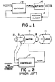
- a DC motor drives a load, a tachometer, and a rotary position feedback element.
- the tachometer produces a signal proportional to the rotational velocity of the shaft, and the controller uses the signal from the tachometer to measure the velocity of the load.
- a rotary position feedback element allows the controller to determine the position of the load and the controller accepts, commands and controls the speed or position of the load.
- the controller given a desired position, determines the position error by taking the difference between the desired position and the actual position as measured by the rotary position feedback element. The controller uses this position error to generate a desired velocity. That is, as the position error decreases, so does the desired velocity. The controller then uses the desired velocity and the tachometer velocity feedback signal to determine the value of the motor actuation signal. Motion control systems using a control strategy such as this are used in a myriad of industrial process control applications.
- Some servo control designers have tried to eliminate the velocity feedback element. Their rationale has been that the tachometer is expensive and requires circuitry which handles the analog signal which tachometers produce. The controller must therefore contain a great deal of analog circuitry, and such circuitry increases the cost and complexity of the controller. The analog circuitry must also be adjusted carefully. Furthermore, these controller designers saw that the velocity is available by differentiating the position information. This is, if the position of the load is noted at two known times, the two position measurements may be subtracted and divided by the time interval in order to give the velocity.
- the prior art method can produce a precise velocity. For example, assume that a motion system, which we will call an "axis", is moving at one million (1,000,000) counts per second. Assume that a count is the smallest element of distance which the controller can measure. If the controller samples the position every millisecond (0.001 second), then the velocity may be found by dividing the change in distance by the time.
- the precision with which the velocity is measured can be found if the velocity is expressed in counts per sample millisecond (1000/msec.). Since a change of one position count can be distinguished, velocity measurement, is precise to one part in one thousand or a possible error of no more than 0.1%, assuming that there is significantly smaller error in timing the sampling of position. This precision is quite good for motion-control systems.
- the velocity measurement precision is found by expressing the velocity in counts per sample period or counts per millisecond.
- the velocity is one count per millisecond (I/msec.).
- the precisiion is therefore only within one part in one or 100%. A possible error of 100% is poor in any motion control system.
- a unique combination of hardware and microprocessor-driven software can comprise a machine using a very different principle from the prior art, a principle which is capable of substantially better measurement of velocity at low velocities.
- the system of this invention measures velocities over five orders of magnitude (a factor of 100,000) with a maximum steady state error of 0.l%.
- the invention also makes it possible to increase the number of axes on a single circuit board by a factor of three or more.
- the solution to the problem of building a servo controller which does not include a tachometer is to measure the time between groups of subsequent quadrature transitions.
- the invention employs a rotary-position sensor which produces what is known as "discrete quadrature", which is a two-bit digital signal in Gray code. As the rotary-position sensor rotates through a fixed angle, the quadrature signal changes.
- quadrature transition is used to refer to the movement of the rotary-position sensor through a sufficient angle for the sensor's quadrature output to advance to the subsequent Gray code pattern.
- a group of quadrature transitions is two or more quadrature transitions.
- count or "position count” means the rotary-position sensor's shaft angle between subsequent quadrature transitions.
- position means the number of position counts from a reference zero count.
- velocity then means the number of counts per second at which the rotary-position sensor is turning.
- the invention thus includes a method for measuring the velocity of a servo shaft driven cyclically by a motor, without employing a tachometer.
- the method begins by producing from movement of the shaft (axis) a pair of signals in quadrature with transitions expressible in Gray code for each cycle as 00, 01, 11, 10 and then back to 00. It also produces, as from a clock, a large number of evenly spaced pulses per group of quadrature transitions at all speeds of the shaft.
- the method continues by reading the number of clock pulses between two selected quadrature transitions, and then determines the velocity by dividing the total number of quadrature transitions between the selected transitions by the total number of clock pulses during the same time.
- the method comprises reading through a FIFO (first-in, first-out) memory a first time when a selected quadrature transition occurred, subtracting from said first time a second time of a preceding selected quadrature tansition in order to obtain the number of clock pulses between two selected quadrature transitions.
- FIFO first-in, first-out
- the method includes dividing the number of quadrature transitions by a suitable factor before routing them to the FIFO memory in order to avoid having the computer fall behind said FIFO memory.
- the same factor is subsequently used as a multiplier at the computer.
- the computer determines the factor and controls its application.
- the method When applying the method to a plurality of different servo shafts, the method provides for multiplexing the input quadrature and latching in the FIFO the identity of each shaft to the counts and quadrature identities applying to it.
- the method applies both to a rotating shaft and a reciprocating shaft, and it includes determining from the sequence of the Gray code transitions the direction of shaft movement.
- the apparatus of the invention basically comprises quadrature means for producing from movement of the shaft a pair of signals in quadrature with transitions expressible in Gray code for one cycle as 00, 01, 11, 10 and then back to 00, clock means for providing a large number of evenly spaced counts per group of quadrature transitions at all speeds of the shaft, reading means for determining the number of counts between two selected quadrature transitions, and computer means for dividing the total number of quadrature transitions between the selected transitions by the total number of counts during the same time.
- the apparatus may include FIFO memory means for receiving the number of counts and sending this number to the computer means. Also, there is preferably programmable dividing means preceding the FIFO memory means for dividing the number of quadrature transitions (counts) by a selected factor in order to enable the computer to keep current with the output from the FIFO memory means.
- This computer means preferably includes means for determining when such factor is needed and what the factor should be, and for supplying the factor to the programmable divider means and the reciprocal thereof to the portion of the computer performing its own dividing step.
- the apparatus When the apparatus is used with a plurality of shafts, it includes multiplexing means for sending appropriate signals from each shaft and latching means in the FIFO memory means for linking the appropriate data with the correct shaft.
- the systems also have direction determining means in the computer actuated by the cyclic order of the Gray code for determining the direction of movement of the shaft.
- the precision was shown to be one part in one or a possible error of 100%.
- the precision is the precision with which the time between the selected quadrature transitions is measured. If the time is, for example, measured in microseconds and sampled every millisecond, the error is reduced to one part in one thousand or 0. %.
- quadrature transition means the movement of the rotary-position sensor through a sufficient angle for the sensor's quadrature output to advance to the subsequent Gray code pattern.
- count or "position count” mean the rotary-position sensor's shaft angle between subsequent quadrature transitions.
- position means the number of position counts from a reference zero count.
- velocity means the number of counts per second at which the rotary-position sensor is turning.
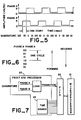
- FIG. 7 exemplifies a simplified form of the invention.
- the quadrature apparatus of Figure 4 is here termed a front end processor-20 and it is linked to a microprocessor or computer 21.
- the computer 21 maintains overall control of the front end processor 20. Because the front end processor 20 can process quadrature transitions faster than can the computer 21, a buffer is placed between the front end processor 20 and the computer 21. This buffer is a first-in-first-out memory 22 which is known as a FIFO.
- the FIFO 22 is capable of being written to by the front end processor 20 for a short period of time at a rate faster than the computer 21 can read from the FIFO 22.
- the nature of the front end processor 20 is such that the capacity of the FIFO 22 will not be exceeded.
- a time source 23 supplies the time to the FIFO 22.
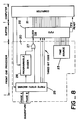
- FIG 8 shows a preferred embodiment of a single axis circuit utilising the present art.
- This circuit includes the front end processor 20 and a computer or microprocessor 21.
- the computer 21 When coupled to the front end processor 20, the computer 21 is able to determine the position and velocity of a single axis of quadrature. It is important to note that the front end processor 20 does not itself maintain the position of the axis nor does it measure the velocity. Only in conjunction with the computer 21 does the front end processor 20 enable the computer 21 to measure position and velocity.
- the prior art typically contains dedicated circuitry which maintains the current position, and if a computer is used, the computer merely reads the position count from this dedicated circuitry.
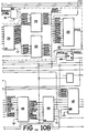
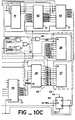
- Figure 8 is slightly simpler than the circuit diagram which was used for the system reduced to practise (see Figures IOA, IOB, and IOC), since incorporation of several integrated circuits into a single diagram block eases the understanding of the concept.
- Figure 8 includes the essential parts of the concept, and accurately describes the invention.
- a finite state machine 25 provides the logic 19 but accepts as inputs the quadrature from an axis of servo.
- the finite state machine 25 detects transitions of the quadrature and responds to every transition of the quadrature. The method in which it responds is dependent upon both the type of quadrature transition which occurs and also the input it receives from the computer 21.
- the FIFO 22 accepts inputs from the finite state machine 25 and the time source 23.
- a programmable divider 26 accepts inputs from the finite state machine 25, and sends its output via an OR gate 27 to a clock 28 of the FIFO 22, the FIFO 22 latches the time presented by the time source 23 as well as the signals from the finite state machine 25.
- the computer 21 instructs the finite state machine 25 to report all transitions of the quadrature directly to the FIFO 22 and not by way of the programmable divider 26.
- the finite state machine 25 produces a three-bit code which indicates that the event which is to be written into the FIFO 22 is a "normal, non-divider transition".
- the finite state machine 25 causes the FIFO 22 to latch or record the three-bit code as well as the current time as presented by the time source 23.
- the finite state machine 25 causes the latching by sending a signal to the FIFO 22 via direct passage to the OR gate 27.
- a ready signal becomes true and informs the computer 21 that a value exists to be read from the FIFO 22.
- the computer 21 reads the FIFO 22, it checks the three-bit code and determines that the event in the FIFO 22 is a "normal, non-divider" transition.
- the computer 21 adds one to the current axis position if the axis is moving in a positive direction and subtracts one if it is moving in a negative direction.
- the computer 21 then subtracts from the time value read from the FIFO 22 the time of the last transition. This difference is the period of the axis.
- the computer 21 programs the programmable divider 26 to divide by two.
- the computer 21 then instructs the finite state machine 25 to route all further transitions to the programmable divider 26 and not directly to the FIFO 22.
- the finite state machine 25 now uses a different code from that used in Condition 1.
- the finite state machine 25 sends the three-bit code to the FIFO 22 which is "normal transition, divider".
- the finite state machine 25 routes the transition to the programmable divider 26. Since the programmable divider has been programmed to divide by two, every other transition will cause the output of the programmable divider 26 to send a transition via the OR gate 27 to the FIFO 22. The FIFO 22 is caused to latch the current time from the time source 23 as well as the three-bit code generated by the finite state machine 25 which is "normal transition, divider".
- the computer 21 senses that a value was latched into the FIFO 22 by means of the ready line.
- the computer 21 reads the FIFO 22 and determines from the three-bit code that this event is a "normal transition, divider".
- the computer 21 adds two (the value of the divider) to an internal variable which represents the current axis position if the axis is moving in the positive direction and subtracts two if it is moving in the negative direction.
- the computer 21 subtracts from the time value read from the FIFO 22 the time of the last transition.
- the computer 21 must re-adjust the programmable divider 26.
- the computer 21 first instructs the finite state machine 25 to route all further transitions directly to the FIFO 22.
- the computer 21 next reads from the programmable divider 26 the remainder of the programmed count.
- the computer 21 then adjusts the axis position by the remainder of the programmable divider 26.
- the remainder of the programmable divider 26 is the count of all transitions which were routed to the programmable divider 26 since the last output of the programmable divider 26.
- the computer 21 next programs the programmable divider 26 with the new value which in this case is three.
- the computer 21 next instructs the finite state machine 25 to route all further transitions of the quadrature to the programmable divider 26 and not directly to the FIFO 22.
- the use of the FIFO 22 to accept all transitions of the quadrature during the time in which the computer 21 changes the divisor of the programmable divider 26 demonstrates what was stated earlier, that the FIFO 22 is an important circuit element when the front end processor is subjected to quadrature rates which are in excess of the rate at which the computer 21 can remove transitions from the FIFO 22. For example, if the rate of transitions or the velocity of the axis is one million counts per second (1,000,000/sec) and the process of changing the divider takes ten microseconds (10 ⁇ sec), we expect that ten transitions will be placed in the FIFO 22 during the time in which the computer 21 is changing the divisor of the programmable divider 26. Because these transitions must be counted in order to maintain accuracy of position, the FIFO 22 is an essential component of the preferred embodiment.
- the function of the FIFO 22 could be provided in other circuit forms, especially if implemented with custom integrated circuits.
- Conditions I, 2, and 3 show a trend of increasing velocities. The trend may be extended to the limit of the resolution of the time source 23 or the circuit speeds of the finite state machine 25 or the FIFO 22.
- the programmable divider 26 is not used, and the remainder of the programmable divider 26 is applied to the axis position as was done in Condition 3.
- axis direction Assume that the front end processor 20 is functioning as in Condition I. Then assume that the axis slows to a stop and then begins turning in the opposite direction. Upon the first quadrature transition in the opposite direction, the finite state machine 25 will detect the reversal and change the code which it presents to the FIFO 22 under this condition from "normal, non-divider event" to "direction change".
- the computer 21 When the computer 21 reads this transition from the FIFO 22, the computer will change its record of the axis direction. Upon the next transition, therefore, the computer will correctly apply the transition to the axis position.
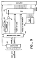
- FIG. 9 shows that the quadrature from eight axes of servo is applied to a multiplexer 30 which allows the finite state machine 25 to examine one of the eight axes by causing the multiplexer 30 to select the desired axis.
- the finite state machine 25 produces a three-bit axis number which is routed to the FIFO 22.
- the computer 21 is thus able to read a value from the FIFO 22 and deduce to which axis the transition in the FIFO 22 refers.
- a ten-bit counter 38 (e.g. 74LS49I) is clocked at I MHz and produces a ten-bit word which is routed to the FIFO portions 36 and 37.
- the finite-state machine 25 contains a clock driver 40 (e.g. 74S74) which divides a 20MHz signal and produces a 10MHz signal and its complement. These signals are used throughout the circuit.
- the axis number is used by several circuit elements. The axis number is produced by a counter 41 (e.g. 74LS162) and latched by a latch 42 (e.g. 74S374).
- a multiplexer 43 e.g. 74S257) is also used to choose between the current axis number and the previous axis number.
- the core of the finite-state machine 25 is made up of a read-only memory (ROM) 45 (e.g. 27S29) and two read-write memories (RAM) 46 and 47 (both, e.g. 27S07A).
- the ROM 45 is presented with the current machine state from one RAM 46 via a latch 48 (e.g. 74S374).
- the ROM 45 is also presented with the current quadrature state from the multiplexer 30 also via the latch 48.
- the ROM 45 is also presented with two bits which may be written by the computer 21 and enabled by a counter 50 (e.g. 74LS 168), a flip-flop 51 (e.g. 74S74), and gates 52, 53 and 54. These two bits allow the computer 21 to command the front-end processor 20 to route quadrature transitions either through the programmable divider 26 or directly to the FIFO 22.
- the ROM 45 is also presented with a bit which indicates that the time source counter 38 is about to roll over.
- the ROM 45 uses the state information as an address and produces an eight-bit data word which represents the next state. (A listing of the contents of the ROM 45 is included hereinafter as appendix A).
- This next state is latched by a latch 55 (e.g. 74S374).
- Four bits are fed back to the RAM 46 which is addressed by the axis number.
- Four bits of the next state are fed forward to the second RAM 47 which feeds a latch 56.
- the output of the latch 56 (e.g. 74S374) is a four-bit word of which three-bits are the code and one bit indicates whether an event should be recorded in the FIFO 36 and 37.
- An AND/OR gate 57 uses the signal from a flip-flop 58 (e.g. 74S 175) to determine whether the programmable divider 26 or the RAM 56 should determine whether an event is recorded in the FIFOs 36 and 37.
- the output of the AND/OR gate 57 is routed to a NOR gate 60 which acts to sychronize the closing of the FIFOs 36 and 37 with the 10MHz clock.
- a flip-flop 61 (e.g. 74S175) and gates 62 and 63 serve to cause the FIFO 36 and 37 to record an event which indicates that the time source counter 38 is about to roll over. If this event where not recorded and the rolling over of the time source counter 38 were not recorded, the computer 21 could not properly determine the time elapsed between quadrature transitions.
Landscapes
- Engineering & Computer Science (AREA)
- General Physics & Mathematics (AREA)
- Physics & Mathematics (AREA)
- Manufacturing & Machinery (AREA)
- Automation & Control Theory (AREA)
- Human Computer Interaction (AREA)
- Computer Hardware Design (AREA)
- Microelectronics & Electronic Packaging (AREA)
- Control Of Position Or Direction (AREA)
- Transmission And Conversion Of Sensor Element Output (AREA)
- Control Of Velocity Or Acceleration (AREA)
- Control Of Electric Motors In General (AREA)
- Measurement Of Velocity Or Position Using Acoustic Or Ultrasonic Waves (AREA)
Priority Applications (1)
| Application Number | Priority Date | Filing Date | Title |
|---|---|---|---|
| AT85102402T ATE54762T1 (de) | 1984-03-05 | 1985-03-04 | Verfahren und vorrichtung zum messen der geschwindigkeit und der position in einem servomechanismus. |
Applications Claiming Priority (2)
| Application Number | Priority Date | Filing Date | Title |
|---|---|---|---|
| US586250 | 1984-03-05 | ||
| US06/586,250 US4639884A (en) | 1984-03-05 | 1984-03-05 | Method and apparatus for measuring velocity and position in servo systems |
Publications (3)
| Publication Number | Publication Date |
|---|---|
| EP0157191A2 true EP0157191A2 (de) | 1985-10-09 |
| EP0157191A3 EP0157191A3 (en) | 1987-04-22 |
| EP0157191B1 EP0157191B1 (de) | 1990-07-18 |
Family
ID=24344960
Family Applications (1)
| Application Number | Title | Priority Date | Filing Date |
|---|---|---|---|
| EP85102402A Expired - Lifetime EP0157191B1 (de) | 1984-03-05 | 1985-03-04 | Verfahren und Vorrichtung zum Messen der Geschwindigkeit und der Position in einem Servomechanismus |
Country Status (5)
| Country | Link |
|---|---|
| US (1) | US4639884A (de) |
| EP (1) | EP0157191B1 (de) |
| JP (1) | JP2661896B2 (de) |
| AT (1) | ATE54762T1 (de) |
| DE (1) | DE3578677D1 (de) |
Cited By (2)
| Publication number | Priority date | Publication date | Assignee | Title |
|---|---|---|---|---|
| EP0218036A1 (de) * | 1985-08-10 | 1987-04-15 | Target Industries Limited | Steuerungskreise, insbesondere für Servomechanismen |
| CN105717843A (zh) * | 2016-03-23 | 2016-06-29 | 苏州市正步机器制造有限公司 | 一种双伺服同步控制方法以及系统 |
Families Citing this family (35)
| Publication number | Priority date | Publication date | Assignee | Title |
|---|---|---|---|---|
| EP0281616A4 (de) * | 1986-09-04 | 1989-01-26 | North Atlantic Industries | Servosystem. |
| US4896288A (en) * | 1987-02-09 | 1990-01-23 | Allen-Bradley Company, Inc. | Programmable controller input module |
| US4933881A (en) * | 1987-07-30 | 1990-06-12 | Universal Recording Corporation | Variable speed film transport interlock system |
| US4815013A (en) * | 1987-07-30 | 1989-03-21 | Universal Recording Corporation | Variable speed film transport interlock system and method using same |
| US4831510A (en) * | 1987-09-17 | 1989-05-16 | Allen-Bradley Company, Inc. | Encoder and resolver signal processing circuit |
| US4990840A (en) * | 1988-02-19 | 1991-02-05 | The Cross Company | Method and system for controlling a machine tool such as a turning machine |
| US5062064A (en) * | 1989-09-01 | 1991-10-29 | Berkeley Process Control, Inc. | Method and apparatus for measuring velocity in servo systems |
| US5237521A (en) * | 1990-08-20 | 1993-08-17 | Xerox Corporation | High resolution position measurement system |
| JPH06511212A (ja) * | 1991-05-09 | 1994-12-15 | ヌ−テック アンド エンジニアリング インコーポレイテッド | 乗用車用の計器表示方法とシステム |
| US5432421A (en) * | 1991-10-26 | 1995-07-11 | Brose Fahrzeugteile Gmbh & Co. Kg | Process for detecting the position, direction of movement and dynamic characteristic values of remote-controlled displacement of an adjustable object |
| JP2833401B2 (ja) * | 1993-03-23 | 1998-12-09 | 三菱電機株式会社 | 駆動制御装置 |
| EP0727059B1 (de) * | 1994-09-01 | 2001-10-17 | Koninklijke Philips Electronics N.V. | Antrieb und röntgengerät mit einem solchen antrieb |
| US5999168A (en) * | 1995-09-27 | 1999-12-07 | Immersion Corporation | Haptic accelerator for force feedback computer peripherals |
| US6374255B1 (en) * | 1996-05-21 | 2002-04-16 | Immersion Corporation | Haptic authoring |
| US6256011B1 (en) * | 1997-12-03 | 2001-07-03 | Immersion Corporation | Multi-function control device with force feedback |
| US6704683B1 (en) | 1998-04-28 | 2004-03-09 | Immersion Corporation | Direct velocity estimation for encoders using nonlinear period measurement |
| US6529114B1 (en) * | 1998-05-27 | 2003-03-04 | Honeywell International Inc. | Magnetic field sensing device |
| US6275742B1 (en) * | 1999-04-16 | 2001-08-14 | Berkeley Process Control, Inc. | Wafer aligner system |
| US6564168B1 (en) * | 1999-09-14 | 2003-05-13 | Immersion Corporation | High-resolution optical encoder with phased-array photodetectors |
| US6693626B1 (en) * | 1999-12-07 | 2004-02-17 | Immersion Corporation | Haptic feedback using a keyboard device |
| US6563280B2 (en) * | 2000-03-06 | 2003-05-13 | Whedco, Inc. | Pulse based servo motor controlled labeler |
| US7084854B1 (en) * | 2000-09-28 | 2006-08-01 | Immersion Corporation | Actuator for providing tactile sensations and device for directional tactile sensations |
| US6937033B2 (en) * | 2001-06-27 | 2005-08-30 | Immersion Corporation | Position sensor with resistive element |
| US6904823B2 (en) * | 2002-04-03 | 2005-06-14 | Immersion Corporation | Haptic shifting devices |
| US8917234B2 (en) | 2002-10-15 | 2014-12-23 | Immersion Corporation | Products and processes for providing force sensations in a user interface |
| US8992322B2 (en) * | 2003-06-09 | 2015-03-31 | Immersion Corporation | Interactive gaming systems with haptic feedback |
| JP4567989B2 (ja) * | 2004-02-06 | 2010-10-27 | 日立ビアメカニクス株式会社 | 移動体のサーボ制御装置及びレーザ加工装置 |
| US7082823B1 (en) * | 2005-01-14 | 2006-08-01 | Honeywell International, Inc. | Digital signal processing back biased hall effect muzzle velocity measurement system |
| US7825903B2 (en) * | 2005-05-12 | 2010-11-02 | Immersion Corporation | Method and apparatus for providing haptic effects to a touch panel |
| US8157650B2 (en) | 2006-09-13 | 2012-04-17 | Immersion Corporation | Systems and methods for casino gaming haptics |
| US9486292B2 (en) | 2008-02-14 | 2016-11-08 | Immersion Corporation | Systems and methods for real-time winding analysis for knot detection |
| US9104791B2 (en) * | 2009-05-28 | 2015-08-11 | Immersion Corporation | Systems and methods for editing a model of a physical system for a simulation |
| JP5943671B2 (ja) * | 2012-03-28 | 2016-07-05 | 日本電産サンキョー株式会社 | エンコーダ装置および位置データの生成方法 |
| US9866924B2 (en) | 2013-03-14 | 2018-01-09 | Immersion Corporation | Systems and methods for enhanced television interaction |
| US10320594B2 (en) * | 2016-07-20 | 2019-06-11 | Texas Instruments Incorporated | Method of determining a direction of rotation and valid transitions of quadrature pulses |
Family Cites Families (18)
| Publication number | Priority date | Publication date | Assignee | Title |
|---|---|---|---|---|
| US4245297A (en) * | 1964-07-27 | 1981-01-13 | Bunker Ramo Corporation | Positioning control system |
| JPS5022416B1 (de) * | 1969-05-14 | 1975-07-30 | ||
| US3710265A (en) * | 1971-04-01 | 1973-01-09 | Howe Richardson Scale Co | Quadrature-to-serial pulse converter |
| US3728565A (en) * | 1971-07-21 | 1973-04-17 | Eaton Corp | Device for sensing the direction and speed of a shaft |
| DE2150397B1 (de) * | 1971-10-09 | 1973-03-01 | Licentia Gmbh | Numerische Arbeitsmaschinensteuerung |
| US3767902A (en) * | 1972-12-12 | 1973-10-23 | Essex International Inc | Engine member position predictor |
| US4040026A (en) * | 1974-05-08 | 1977-08-02 | Francois Gernelle | Channel for exchanging information between a computer and rapid peripheral units |
| US4094371A (en) * | 1976-02-04 | 1978-06-13 | Ferrell Herbert W | Digital display for weighing scales |
| JPS5311860A (en) * | 1976-07-20 | 1978-02-02 | Asahi Chemical Ind | Method of welding titanium or zirconium clad plates |
| DE2828285C3 (de) * | 1978-06-28 | 1982-06-09 | Diehl GmbH & Co, 8500 Nürnberg | Verfahren und Vorrichtung zur Erzeugung und Verarbeitung elektrischer Impulse |
| US4214193A (en) * | 1978-10-10 | 1980-07-22 | Hewlett-Packard Company | Digital servo anti-hunt circuit |
| JPS55160859A (en) * | 1979-06-04 | 1980-12-15 | Hitachi Ltd | Method for detecting speed of vehicle |
| US4331917A (en) * | 1979-12-13 | 1982-05-25 | Caterpillar Tractor Co. | Speed and direction sensing circuit |
| EP0045761A1 (de) * | 1980-02-14 | 1982-02-17 | Zeus International Trading Co. Limited | Verfahren und system zur positionssteuerung |
| US4434470A (en) * | 1981-02-09 | 1984-02-28 | The Bendix Corporation | Speed measurement system with means for calculating the exact time period of a known quantity of speed pulses |
| JPS57169611A (en) * | 1981-04-13 | 1982-10-19 | Tokyo Optical Co Ltd | Measuring device for angular displacement |
| US4429267A (en) * | 1981-06-22 | 1984-01-31 | Manhattan Engineering Company, Inc. | Digital positioning systems having high accuracy |
| US4520781A (en) * | 1981-09-16 | 1985-06-04 | Mitsubishi Denki Kabushiki Kaisha | Ignition control system of internal combustion engine |
-
1984
- 1984-03-05 US US06/586,250 patent/US4639884A/en not_active Expired - Lifetime
-
1985
- 1985-03-04 DE DE8585102402T patent/DE3578677D1/de not_active Expired - Lifetime
- 1985-03-04 EP EP85102402A patent/EP0157191B1/de not_active Expired - Lifetime
- 1985-03-04 JP JP60041364A patent/JP2661896B2/ja not_active Expired - Lifetime
- 1985-03-04 AT AT85102402T patent/ATE54762T1/de not_active IP Right Cessation
Cited By (2)
| Publication number | Priority date | Publication date | Assignee | Title |
|---|---|---|---|---|
| EP0218036A1 (de) * | 1985-08-10 | 1987-04-15 | Target Industries Limited | Steuerungskreise, insbesondere für Servomechanismen |
| CN105717843A (zh) * | 2016-03-23 | 2016-06-29 | 苏州市正步机器制造有限公司 | 一种双伺服同步控制方法以及系统 |
Also Published As
| Publication number | Publication date |
|---|---|
| EP0157191A3 (en) | 1987-04-22 |
| DE3578677D1 (de) | 1990-08-23 |
| JPS60228965A (ja) | 1985-11-14 |
| EP0157191B1 (de) | 1990-07-18 |
| US4639884A (en) | 1987-01-27 |
| JP2661896B2 (ja) | 1997-10-08 |
| ATE54762T1 (de) | 1990-08-15 |
Similar Documents
| Publication | Publication Date | Title |
|---|---|---|
| US4639884A (en) | Method and apparatus for measuring velocity and position in servo systems | |
| US3781490A (en) | Web tension and speed control in a reel-to-reel web transport | |
| ES469977A1 (es) | Un aparato de transporte de cinta de carrete a carrete. | |
| EP0164256A1 (de) | Motorsteuergerät für Bandantriebssystem mit Spulen | |
| EP0201605A1 (de) | System zum regeln der geschwindigkeit eines servomotors | |
| EP0176301A2 (de) | Verfahren und Gerät zum Transport eines Aufzeichnungsträgers mit einem anpassbaren Geschwindigkeitsänderungs-Profil | |
| EP0051417B1 (de) | Verfahren und Gerät zur Verwendung beim Justieren eines Schaltelements in einer numerisch gesteuerten Maschine | |
| US4809094A (en) | Method of accessing data recorded on a disk at a high speed | |
| JPS6364594A (ja) | ロ−タの昇降装置 | |
| WO1991013388A1 (en) | Improvements in or relating to actuator control | |
| WO2001054264A1 (fr) | Procede de production du chlore | |
| JPS60112106A (ja) | 移動機構の駆動制御方法 | |
| JP2674407B2 (ja) | 磁気記録再生装置 | |
| JPS613378A (ja) | ヘツド駆動方式 | |
| JPS63304307A (ja) | 速度制御装置 | |
| JPS62150409A (ja) | デジタルサ−ボ制御における速度制御方法 | |
| JPS58179954A (ja) | テ−プ巻取り装置 | |
| JPH02144606A (ja) | 高速アクセス制御方式 | |
| JPH02257456A (ja) | モータ駆動制御回路 | |
| JP2803416B2 (ja) | 磁気記録再生装置 | |
| JP2701253B2 (ja) | テープ状記録媒体再生装置 | |
| JPS63193213A (ja) | パルスエンコ−ダを有するデイジタルサ−ボシステムの速度制御装置 | |
| JPH01165059A (ja) | 磁気テープ再生装置 | |
| JPH02187970A (ja) | 磁気ディスク装置 | |
| JPH04282710A (ja) | 速度制御方式 |
Legal Events
| Date | Code | Title | Description |
|---|---|---|---|
| PUAI | Public reference made under article 153(3) epc to a published international application that has entered the european phase |
Free format text: ORIGINAL CODE: 0009012 |
|
| AK | Designated contracting states |
Designated state(s): AT BE CH DE FR GB IT LI LU NL SE |
|
| PUAL | Search report despatched |
Free format text: ORIGINAL CODE: 0009013 |
|
| AK | Designated contracting states |
Kind code of ref document: A3 Designated state(s): AT BE CH DE FR GB IT LI LU NL SE |
|
| 17P | Request for examination filed |
Effective date: 19871007 |
|
| 17Q | First examination report despatched |
Effective date: 19881122 |
|
| GRAA | (expected) grant |
Free format text: ORIGINAL CODE: 0009210 |
|
| AK | Designated contracting states |
Kind code of ref document: B1 Designated state(s): AT BE CH DE FR GB IT LI LU NL SE |
|
| PG25 | Lapsed in a contracting state [announced via postgrant information from national office to epo] |
Ref country code: SE Effective date: 19900718 Ref country code: BE Effective date: 19900718 Ref country code: AT Effective date: 19900718 |
|
| REF | Corresponds to: |
Ref document number: 54762 Country of ref document: AT Date of ref document: 19900815 Kind code of ref document: T |
|
| ITF | It: translation for a ep patent filed | ||
| REF | Corresponds to: |
Ref document number: 3578677 Country of ref document: DE Date of ref document: 19900823 |
|
| ET | Fr: translation filed | ||
| ITTA | It: last paid annual fee | ||
| PG25 | Lapsed in a contracting state [announced via postgrant information from national office to epo] |
Ref country code: LU Free format text: LAPSE BECAUSE OF NON-PAYMENT OF DUE FEES Effective date: 19910331 |
|
| PLBE | No opposition filed within time limit |
Free format text: ORIGINAL CODE: 0009261 |
|
| STAA | Information on the status of an ep patent application or granted ep patent |
Free format text: STATUS: NO OPPOSITION FILED WITHIN TIME LIMIT |
|
| 26N | No opposition filed | ||
| REG | Reference to a national code |
Ref country code: GB Ref legal event code: IF02 |
|
| PGFP | Annual fee paid to national office [announced via postgrant information from national office to epo] |
Ref country code: GB Payment date: 20040303 Year of fee payment: 20 |
|
| PGFP | Annual fee paid to national office [announced via postgrant information from national office to epo] |
Ref country code: FR Payment date: 20040309 Year of fee payment: 20 |
|
| PGFP | Annual fee paid to national office [announced via postgrant information from national office to epo] |
Ref country code: NL Payment date: 20040310 Year of fee payment: 20 |
|
| PGFP | Annual fee paid to national office [announced via postgrant information from national office to epo] |
Ref country code: DE Payment date: 20040311 Year of fee payment: 20 |
|
| PGFP | Annual fee paid to national office [announced via postgrant information from national office to epo] |
Ref country code: CH Payment date: 20040317 Year of fee payment: 20 |
|
| PG25 | Lapsed in a contracting state [announced via postgrant information from national office to epo] |
Ref country code: LI Free format text: LAPSE BECAUSE OF EXPIRATION OF PROTECTION Effective date: 20050303 Ref country code: GB Free format text: LAPSE BECAUSE OF EXPIRATION OF PROTECTION Effective date: 20050303 Ref country code: CH Free format text: LAPSE BECAUSE OF EXPIRATION OF PROTECTION Effective date: 20050303 |
|
| PG25 | Lapsed in a contracting state [announced via postgrant information from national office to epo] |
Ref country code: NL Free format text: LAPSE BECAUSE OF EXPIRATION OF PROTECTION Effective date: 20050304 |
|
| REG | Reference to a national code |
Ref country code: GB Ref legal event code: PE20 |
|
| REG | Reference to a national code |
Ref country code: CH Ref legal event code: PL |
|
| NLV7 | Nl: ceased due to reaching the maximum lifetime of a patent |
Effective date: 20050304 |