EP0155643B1 - Vorrichtung zur Bedampfung - Google Patents
Vorrichtung zur Bedampfung Download PDFInfo
- Publication number
- EP0155643B1 EP0155643B1 EP85102965A EP85102965A EP0155643B1 EP 0155643 B1 EP0155643 B1 EP 0155643B1 EP 85102965 A EP85102965 A EP 85102965A EP 85102965 A EP85102965 A EP 85102965A EP 0155643 B1 EP0155643 B1 EP 0155643B1
- Authority
- EP
- European Patent Office
- Prior art keywords
- vacuum
- steel band
- evaporation
- roll
- sealing
- Prior art date
- Legal status (The legal status is an assumption and is not a legal conclusion. Google has not performed a legal analysis and makes no representation as to the accuracy of the status listed.)
- Expired - Lifetime
Links
Images


Classifications
-
- C—CHEMISTRY; METALLURGY
- C23—COATING METALLIC MATERIAL; COATING MATERIAL WITH METALLIC MATERIAL; CHEMICAL SURFACE TREATMENT; DIFFUSION TREATMENT OF METALLIC MATERIAL; COATING BY VACUUM EVAPORATION, BY SPUTTERING, BY ION IMPLANTATION OR BY CHEMICAL VAPOUR DEPOSITION, IN GENERAL; INHIBITING CORROSION OF METALLIC MATERIAL OR INCRUSTATION IN GENERAL
- C23C—COATING METALLIC MATERIAL; COATING MATERIAL WITH METALLIC MATERIAL; SURFACE TREATMENT OF METALLIC MATERIAL BY DIFFUSION INTO THE SURFACE, BY CHEMICAL CONVERSION OR SUBSTITUTION; COATING BY VACUUM EVAPORATION, BY SPUTTERING, BY ION IMPLANTATION OR BY CHEMICAL VAPOUR DEPOSITION, IN GENERAL
- C23C14/00—Coating by vacuum evaporation, by sputtering or by ion implantation of the coating forming material
- C23C14/22—Coating by vacuum evaporation, by sputtering or by ion implantation of the coating forming material characterised by the process of coating
- C23C14/24—Vacuum evaporation
- C23C14/26—Vacuum evaporation by resistance or inductive heating of the source
-
- C—CHEMISTRY; METALLURGY
- C23—COATING METALLIC MATERIAL; COATING MATERIAL WITH METALLIC MATERIAL; CHEMICAL SURFACE TREATMENT; DIFFUSION TREATMENT OF METALLIC MATERIAL; COATING BY VACUUM EVAPORATION, BY SPUTTERING, BY ION IMPLANTATION OR BY CHEMICAL VAPOUR DEPOSITION, IN GENERAL; INHIBITING CORROSION OF METALLIC MATERIAL OR INCRUSTATION IN GENERAL
- C23C—COATING METALLIC MATERIAL; COATING MATERIAL WITH METALLIC MATERIAL; SURFACE TREATMENT OF METALLIC MATERIAL BY DIFFUSION INTO THE SURFACE, BY CHEMICAL CONVERSION OR SUBSTITUTION; COATING BY VACUUM EVAPORATION, BY SPUTTERING, BY ION IMPLANTATION OR BY CHEMICAL VAPOUR DEPOSITION, IN GENERAL
- C23C14/00—Coating by vacuum evaporation, by sputtering or by ion implantation of the coating forming material
- C23C14/22—Coating by vacuum evaporation, by sputtering or by ion implantation of the coating forming material characterised by the process of coating
- C23C14/56—Apparatus specially adapted for continuous coating; Arrangements for maintaining the vacuum, e.g. vacuum locks
- C23C14/562—Apparatus specially adapted for continuous coating; Arrangements for maintaining the vacuum, e.g. vacuum locks for coating elongated substrates
Definitions
- the present invention relates generally to an improvement in or relating to a vacuum evaporator, and more particularly to an improved vacuum evaporation equipment for the continuous evaporation of such metals as zinc under the vacuum environment onto a band or hoop of steel products.
- the metal such as zinc evaporated upon the steel band product would possibly be caused to be re-evaporated therefrom and then deposited onto the interior wall surfaces of the evaporation chamber and the vacuum sealing station held at the relatively low pressure levels while passing therethrough, which deposition would then grow to an excessive extent, after a long running operation.
- This would eventually be a substantial cause of reduction in the operating efficiency of the vacuum evaporation line, such as an extra shut-down of the whole production line for removing thus-deposited zinc from the evaporation chamber and the vacuum sealing station.
- the quantity of re-evaporated zinc will have to be scrapped, which is an immediate and substantial loss of material in the normal operation.
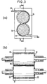
- Fig. 2(a) shows a schematic cut-away view showing in cross section the conventional construction of a vacuum sealing device of pinch roll type
- Fig. 2(b) is a cross-sectional view taken along the line A-A in Fig. 2(a), in which there is shown a pair of upper and lower rolls 01, 01 disposed rotatably in a casing 06, having a web of steel 05 pinched in the sandwiched relationship therebetween.
- the opposite end faces of these paired rolls 01, 01 are placed facing the side wall surfaces of the casing 06 having close gaps 02 therewith, in such a manner that the gaps 02 may be made as small as possible, while allowing a gas to pass therethrough, so that there may be obtained a substantial grade of vacuum within the casing 06. Also, it is arranged such that the casing 06 may be in communication with a vacuum pump, not shown, through an exhaust duct.
- Fig. 3(a) is a schematic side elevational view showing, partly cut away, a vacuum sealing station of bridle type
- Fig. 3(b) is a longitudinal cross-sectional view taken along the line B-B in Fig. 3(a), in which it is seen that the steel band 05 is threaded in the wrapped-around fashion across a pair of upper and lower rolls 01, 01, and that there are a pair of covers 04 of arcuate shape disposed in complementary relationship with the running path of the steel band on the rolls 01, 01.
- the similar problem of deposition of metals in this type sealing station may also be observed the similar problem of deposition of metals in this type sealing station to the case as noted above.
- a vacuum evaporation equipment of the kind defined by the precharacterizing features of claim 1 is known from the CH-A-288 438.
- the steel band to be deposited with evaporated metal is lead through a gap formed in a treatment chamber to which the evaporation vessel is connected and the inner surfaces of this treatment chamber are heated to a higher temperature than the evaporation temperature of the metal to be deposited in order to avoid deposition of the evaporated metal to said surfaces, thereby avoiding dripping of evaporated metal from said surfaces to the steel band.
- Metal vapor re-evaporated from the treated steel band leaving the depositing port may deposit on the inner surfaces of the vacuum vessel and drip down to the treated steel band, thereby causing a deposition layer thereon of minor quality as well as a pollution of the inner surfaces of the vacuum vessel.
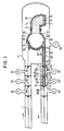
- a strip or band of steel 1 is introduced into a vacuum vessel 2 held at a relatively low pressure in sequence through vacuum block or sealing stations 31, 33 and 34 disposed in serial fashion on the inlet part of the vacuum evaporation process, and the steel band 1 is then deposited with a vapor of metal, for example, zinc which is evaporated from an evaporation vessel 4, while guided along by way of a roll 3, thereafter the steel band 1 is then redirected towards another station in line of a higher pressure in sequence through a series of vacuum sealing stations 6, 29 and 30.
- a vapor of metal for example, zinc
- the steel band 1 which was deposited with solid zinc is surrounded thoroughly by the extension of the heated inner duct 12 so that the re-evaporated vapor of zinc may effectively be prevented from depositing upon the inner duct 12 because of its heat, thus resulting in a vapor of re-evaporated zinc 8 drifting around in the interior of the inner duct 12, which would not deposit any longer upon the steel band 1 as the current component of the vapor of zinc reaches its pressure of saturated vapor P 1 at the current temperature of re-evaporation T, of the solid zinc deposited on the surface of the steel band 1.
- the evaporation vessel 4 is heated to the melting point of zinc by way of a heater 15.
- Molten zinc 14 heated up to the temperature from 430 to 580°C is then put to purge the atmospheric gas, for example, nitrogen therefrom by using a vacuum pump 21, and when the atmosphere in the vacuum vessel reaches the pressure level from 1 to 0.0001 Torr., it will then start evaporation.
- evaporated vapor of zinc 5 guided along with the channel 9, which is also a heated hood is deposited continuously onto the surface of the steel band 1 wrapped around the roll 3.
- a heater 19 extending along the inner circumference of the roll 3.
- the outer surface temperatures of the roll 3 and of the discs on the opposite ends thereof are heated to a point higher than the re-evaporation temperature of the vapor of zinc 5 at the current vapor pressure thereof, for example, 580°C at the pressure level of 1 Torr., or 230°C at the level of 0.0001 Torr.
- an arc-shaped cover member 25 to be heated by using a heater 17 on the entrance side of the steel band 1 existing around the circumference of the roll 3 and also an arc-shaped cover member 10 to be heated by the heater 17 on the outlet side of the roll 3 in such a manner that a substantial volume of zinc vapor 5 may be held from flowing out into the vacuum vessel 2 while being guided along the channel 9, and that the outer surfaces of these cover members 25 and 10 may be heated to such a temperature level as higher than the current re-evaporation temperature of the vapor of zinc 5 at the current vapor pressure thereof, for example, to the level of from 230 to 580°C under the vapor pressure of from 1 to 0.0001 Torr.
- it is ensured to such an advantage that there may occur no deposition of re-evaporated zinc vapor onto the surfaces of the roll 3 as well as the arc-shaped cover members 25 and 10, respectively.
- a similar arcuate cover member 11 having a heater 18 on the side opposite the one where the steel band 1 passes around the circumference of the roll 3 in such a manner that it may be heated by that heater 18 at a point higher than the re-evaporation temperature of the vapor of zinc 5 so that the zinc vapor may be prevented from depositing upon the inner surface of that cover member 11, accordingly.
- a gap 27 defined between this cover member 11 and the roll 3 is made as small as possible to such an extent that there is no contact between the roll 3 and the cover member 11 when installed together, so that the re-evaporated vapor of zinc 8 existing in the inner duct 12 may efficiently be prevented from espacing out into the vacuum vessel 2 owing to a possible pressure loss generated in the extension of gap 27, accordingly.
- the inner duch 12 is operatively connected at its one end to these cover members 10 and 11, while being connected at the opposite end with an expansion allowance to the sealing bar 13 of the vacuum sealing station 6, and also designed to be heated in its longitudinal extension by using a heater 20.
- the vacuum sealing stations 6 and 34 are comprised of a vacuum pump 22, the vacuum sealing stations 29 and 33 are of a vacuum pump 23, and that the vacuum sealing stations 31 and 31 are of a vacuum pump 24, respectively, each of which is evacuated to a vacuum state, and which are designed to give a stepwise reduction of pressures while passing the steel band 1 in sequence therethrough from the atmospheric pressure of 760 Torr., down to the level of 1 to 0.0001 Torr. in the interior of the vacuum vessel 2 where the steel band 1 is subjected to the vacuum evaporation operation.
- heaters in the interior of pairs of sealing rolls 28 at each of the vacuum sealing stations 6, 29, 30 for the purpose of heating the outer circumferential surfaces of these rolls to a point equal to or higherthan the re-evaporation temperature of solid zinc which was deposited upon the steel band 1 so that the vapor of re-evaporated zinc 8 is efficiently prevented from depositing upon these rolls.
- a heater not shown, in each of the sealing bars 13 for heating them to the same temperature level as that of the sealing rolls 28, so that the vapor of re-evaporated zinc 8 may well be prevented from depositing thereupon, accordingly.
- the steel band 1 finished with vacuum evaporation procedure is fed out of the roll 3, passing through the inner duct 12 heated with the heater 20 with the possibility that a re-evaporaton of solid zinc may occur from the deposited surface of the steel band 1.
- inner ducts 32 and 32' with an appropriate expansion allowance between the vacuum sealing stations 6 and 29 and between the vacuum sealing stations 29 and 30 under vacuum condition, which inner ducts are heated by way of the heater 20 for the prevention of re-evaporation of solid zinc during the equipment operation.
- the inner duct per se is formed from a sheet of stainless steel or of ordinary steel, and this duct has its outer surface insulated by using heat insulating material (not shown) so that it may be heated with a small power consumption.
- FIG. 4 there is shown a schematic side elevational view showing, partly cut-away, the general construction of the vacuum sealing station according to the present invention, while Fig. 5 is a fragmentary cross-sectional view taken along the line C-C in Fig. 4.
- the vacuum sealing stations are of pinch-roll type, and in this construction, there are provided pairs of upper and lower rolls 51, only two pairs seen in Fig. 4, mounted rotatably for carrying a band of steel 57 in the sandwiched relationship therebetween in the interior of a casing 56. It is also shown that each of such rolls 51 is designed to be hollow for incorporating a heating unit 52 therein so as to have itself heated thereby.
- Fig. 5 there is shown extending rotating shafts 51a from the opposite ends of each roll 51 outwardly through the side walls of the casing 56, and that there is provided a shaft seal 64 on the outer circumference of each of the rotating shafts 51a in the sliding contact fashion.
- a dust boot of bellow type designated at the reference numeral 63 in Fig. 5.
- side panels 61 formed from carbon or carbon fiber lining of high heat-seizure resisting property on the opposite side ends of the roll 51 in such a manner that they are held resiliently in position against the roll side ends by aid of springs 62.
- a heating unit 55 in the vicinity of the sealing bar 53 for heating the same. It is to be noted that the hollow space in the interior of the casing 56 is in intercommunication with a vacuum pump, not shown, by way of an exhaust duct 58.
- a substantial advantage achieved by the disclosed embodiments of the invention is that the undesired re-evaporation of solid zinc deposited on the product surface may efficiently be prevented from occurring, the quantity of re-evaporated zinc may be held to a minimum, and the undesired deposition of re-evaporated zinc onto the vacuum vessel, the vacuum sealing stations, or the like may well be prevented as far as possible, by virtue of the provision of the inner ducts heated to control according to the invention, thus contributing to the substantial improvement in the operating efficiency, and hence in the productivity of the entire production line.
- the undesired deposition of the metal to be evaporated onto the rolls and the gaps between the rolls and relevant cover members thereto may be efficiently prevented from occurring, by virtue of the provision of the side panels shiftable longitudinally along the axes of the rolls and mounted resiliently on the opposite sides of the rolls, and which are heated to the point higher than the re-evaporation temperature of the metal to be evaporated, thus ensuring the continued normal smooth rotating motion of the rolls, eliminating the adverse effect upon the products, and thus providing the high degree of vacuum in the components involved in the vacuum evaporation equipment, which would eventually enable a vacuum pump of as small as possible capacity to be adapted, accordingly.
Landscapes
- Chemical & Material Sciences (AREA)
- Chemical Kinetics & Catalysis (AREA)
- Engineering & Computer Science (AREA)
- Materials Engineering (AREA)
- Mechanical Engineering (AREA)
- Metallurgy (AREA)
- Organic Chemistry (AREA)
- Physical Vapour Deposition (AREA)
Claims (5)
Applications Claiming Priority (4)
| Application Number | Priority Date | Filing Date | Title |
|---|---|---|---|
| JP51141/84 | 1984-03-19 | ||
| JP5114184A JPS60197876A (ja) | 1984-03-19 | 1984-03-19 | 真空蒸着装置 |
| JP86169/84 | 1984-05-01 | ||
| JP59086169A JPS60234964A (ja) | 1984-05-01 | 1984-05-01 | 真空シ−ル装置 |
Publications (3)
| Publication Number | Publication Date |
|---|---|
| EP0155643A2 EP0155643A2 (de) | 1985-09-25 |
| EP0155643A3 EP0155643A3 (en) | 1987-11-25 |
| EP0155643B1 true EP0155643B1 (de) | 1990-06-27 |
Family
ID=26391672
Family Applications (1)
| Application Number | Title | Priority Date | Filing Date |
|---|---|---|---|
| EP85102965A Expired - Lifetime EP0155643B1 (de) | 1984-03-19 | 1985-03-14 | Vorrichtung zur Bedampfung |
Country Status (6)
| Country | Link |
|---|---|
| US (1) | US4649860A (de) |
| EP (1) | EP0155643B1 (de) |
| KR (1) | KR890004043B1 (de) |
| AU (1) | AU553239B2 (de) |
| CA (1) | CA1233016A (de) |
| DE (2) | DE3578437D1 (de) |
Families Citing this family (12)
| Publication number | Priority date | Publication date | Assignee | Title |
|---|---|---|---|---|
| US4829189A (en) * | 1986-07-18 | 1989-05-09 | Sando Iron Works Co., Ltd. | Apparatus for low-temperature plasma treatment of sheet material |
| SE465321B (sv) * | 1988-02-09 | 1991-08-26 | Nisshin Steel Co Ltd | Foerfarande foer framstaellning av zink-legeringsplaeterad titantaetad staalplaat samt anvaendning av densamma |
| AU2710099A (en) * | 1998-03-27 | 1999-10-18 | Empa Eidgenossische Materialprufungs- Und Forschungsanstalt | Vacuum strip coating installation |
| US9017480B2 (en) * | 2006-04-06 | 2015-04-28 | First Solar, Inc. | System and method for transport |
| WO2011065999A1 (en) * | 2008-12-18 | 2011-06-03 | Veeco Instruments Inc. | Linear deposition source |
| US20100159132A1 (en) * | 2008-12-18 | 2010-06-24 | Veeco Instruments, Inc. | Linear Deposition Source |
| US20100282167A1 (en) * | 2008-12-18 | 2010-11-11 | Veeco Instruments Inc. | Linear Deposition Source |
| JP5597722B2 (ja) * | 2009-12-24 | 2014-10-01 | ポスコ | 鋼板通板装置とこれを含む鋼板表面処理装置及び鋼板の表面処理方法 |
| FR2992978B1 (fr) * | 2012-07-06 | 2014-07-11 | Commissariat Energie Atomique | Dispositif de generation de cibles a base d'hydrogene et/ou de deuterium solide |
| UA116262C2 (uk) | 2013-08-01 | 2018-02-26 | Арселорміттал | Сталевий лист з цинковим покриттям |
| UA117592C2 (uk) | 2013-08-01 | 2018-08-27 | Арселорміттал | Пофарбований оцинкований сталевий лист та спосіб його виготовлення |
| JP6801887B2 (ja) * | 2018-10-18 | 2020-12-16 | 株式会社クリエイティブコーティングス | 成膜装置 |
Family Cites Families (5)
| Publication number | Priority date | Publication date | Assignee | Title |
|---|---|---|---|---|
| CH288438A (de) * | 1950-10-23 | 1953-01-31 | Alois Dr Vogt | Verfahren zum Aufbringen von Metallüberzügen auf langgestrecktes Arbeitsgut, sowie Einrichtung zur Durchführung des Verfahrens. |
| US3278331A (en) * | 1965-07-26 | 1966-10-11 | Pennsalt Chemicals Corp | Process for coating steel with zinc |
| GB1355798A (en) * | 1970-05-28 | 1974-06-05 | Bekaert Sa Nv | Process for the deposition of metal coatings on to metal elements and on apparatus therefor |
| US3989862A (en) * | 1970-10-13 | 1976-11-02 | Jones & Laughlin Steel Corporation | Method and apparatus for vapor-depositing coatings on substrates |
| US3788877A (en) * | 1972-07-20 | 1974-01-29 | Steel Corp | Method for producing adherent,ductile zinc coating on ferrous substrates by vacuum deposition |
-
1985
- 1985-03-14 EP EP85102965A patent/EP0155643B1/de not_active Expired - Lifetime
- 1985-03-14 DE DE8585102965T patent/DE3578437D1/de not_active Expired - Lifetime
- 1985-03-14 DE DE198585102965T patent/DE155643T1/de active Pending
- 1985-03-15 AU AU40012/85A patent/AU553239B2/en not_active Ceased
- 1985-03-19 US US06/713,743 patent/US4649860A/en not_active Expired - Lifetime
- 1985-03-19 CA CA000476897A patent/CA1233016A/en not_active Expired
- 1985-03-19 KR KR1019850001760A patent/KR890004043B1/ko not_active Expired
Also Published As
| Publication number | Publication date |
|---|---|
| AU553239B2 (en) | 1986-07-10 |
| EP0155643A3 (en) | 1987-11-25 |
| KR850006551A (ko) | 1985-10-14 |
| AU4001285A (en) | 1985-09-26 |
| CA1233016A (en) | 1988-02-23 |
| DE155643T1 (de) | 1986-01-30 |
| DE3578437D1 (de) | 1990-08-02 |
| KR890004043B1 (ko) | 1989-10-18 |
| US4649860A (en) | 1987-03-17 |
| EP0155643A2 (de) | 1985-09-25 |
Similar Documents
| Publication | Publication Date | Title |
|---|---|---|
| EP0155643B1 (de) | Vorrichtung zur Bedampfung | |
| US4934444A (en) | Device and method for cooling rolls | |
| US4552092A (en) | Vacuum vapor deposition system | |
| EP0995807B1 (de) | Verfahren und Vorrichtung zur Abdichtung in einem Durchlaufwärmebehandlungsofen | |
| US3868106A (en) | Vacuum chamber seal | |
| US4537243A (en) | Method of and apparatus for steam preheating endless flexible casting belt | |
| US4242154A (en) | Preheat and cleaning system | |
| KR900001092B1 (ko) | 금속스트립의 냉각장치 | |
| US4681536A (en) | Charging sluice for annealing oven | |
| JPS6353262B2 (de) | ||
| CA1182618A (en) | Steam preheating the endless flexible casting belt in a continuous casting machine | |
| JPH07116580B2 (ja) | 冷却機能付き保持帯を有する合金化炉 | |
| US4524821A (en) | Apparatus to improve casting band life | |
| US5431755A (en) | Method of and arrangement for thermal treatment of continuously moving metal bands | |
| JPS624865A (ja) | 真空処理装置のシ−ル装置 | |
| JP3757402B2 (ja) | 真空シール装置 | |
| RU2006100290A (ru) | Способ и установка для охлаждения металлической ленты при ее протягивании | |
| CA1221232A (en) | Vacuum vapor deposition system | |
| JPS63238273A (ja) | ヒ−トパイプロ−ル | |
| GB2085779A (en) | Steam preheating and endless flexible casting belt in a continuous casting machine | |
| JPS63179066A (ja) | 巻付けロ−ル | |
| JPS63179064A (ja) | 巻付けロ−ル | |
| JPS63179063A (ja) | 巻付けロ−ル | |
| JPH01184270A (ja) | 真空蒸着装置 | |
| JPS63179065A (ja) | 巻付けロ−ル |
Legal Events
| Date | Code | Title | Description |
|---|---|---|---|
| PUAI | Public reference made under article 153(3) epc to a published international application that has entered the european phase |
Free format text: ORIGINAL CODE: 0009012 |
|
| 17P | Request for examination filed |
Effective date: 19850411 |
|
| AK | Designated contracting states |
Designated state(s): BE DE FR GB |
|
| EL | Fr: translation of claims filed | ||
| DET | De: translation of patent claims | ||
| PUAL | Search report despatched |
Free format text: ORIGINAL CODE: 0009013 |
|
| AK | Designated contracting states |
Kind code of ref document: A3 Designated state(s): BE DE FR GB |
|
| 17Q | First examination report despatched |
Effective date: 19890320 |
|
| GRAA | (expected) grant |
Free format text: ORIGINAL CODE: 0009210 |
|
| AK | Designated contracting states |
Kind code of ref document: B1 Designated state(s): BE DE FR GB |
|
| ET | Fr: translation filed | ||
| REF | Corresponds to: |
Ref document number: 3578437 Country of ref document: DE Date of ref document: 19900802 |
|
| PLBE | No opposition filed within time limit |
Free format text: ORIGINAL CODE: 0009261 |
|
| STAA | Information on the status of an ep patent application or granted ep patent |
Free format text: STATUS: NO OPPOSITION FILED WITHIN TIME LIMIT |
|
| 26N | No opposition filed | ||
| PGFP | Annual fee paid to national office [announced via postgrant information from national office to epo] |
Ref country code: GB Payment date: 19970305 Year of fee payment: 13 |
|
| PGFP | Annual fee paid to national office [announced via postgrant information from national office to epo] |
Ref country code: FR Payment date: 19970313 Year of fee payment: 13 |
|
| PGFP | Annual fee paid to national office [announced via postgrant information from national office to epo] |
Ref country code: DE Payment date: 19970321 Year of fee payment: 13 |
|
| PGFP | Annual fee paid to national office [announced via postgrant information from national office to epo] |
Ref country code: BE Payment date: 19970521 Year of fee payment: 13 |
|
| PG25 | Lapsed in a contracting state [announced via postgrant information from national office to epo] |
Ref country code: GB Free format text: LAPSE BECAUSE OF NON-PAYMENT OF DUE FEES Effective date: 19980314 |
|
| PG25 | Lapsed in a contracting state [announced via postgrant information from national office to epo] |
Ref country code: FR Free format text: THE PATENT HAS BEEN ANNULLED BY A DECISION OF A NATIONAL AUTHORITY Effective date: 19980331 Ref country code: BE Free format text: LAPSE BECAUSE OF NON-PAYMENT OF DUE FEES Effective date: 19980331 |
|
| BERE | Be: lapsed |
Owner name: NISSHIN STEEL CO. LTD Effective date: 19980331 Owner name: MITSUBISHI JUKOGYO K.K. Effective date: 19980331 |
|
| GBPC | Gb: european patent ceased through non-payment of renewal fee |
Effective date: 19980314 |
|
| PG25 | Lapsed in a contracting state [announced via postgrant information from national office to epo] |
Ref country code: DE Free format text: LAPSE BECAUSE OF NON-PAYMENT OF DUE FEES Effective date: 19981201 |
|
| REG | Reference to a national code |
Ref country code: FR Ref legal event code: ST |