EP0155643B1 - Vacuum evaporation equipment - Google Patents
Vacuum evaporation equipment Download PDFInfo
- Publication number
- EP0155643B1 EP0155643B1 EP85102965A EP85102965A EP0155643B1 EP 0155643 B1 EP0155643 B1 EP 0155643B1 EP 85102965 A EP85102965 A EP 85102965A EP 85102965 A EP85102965 A EP 85102965A EP 0155643 B1 EP0155643 B1 EP 0155643B1
- Authority
- EP
- European Patent Office
- Prior art keywords
- vacuum
- steel band
- evaporation
- roll
- sealing
- Prior art date
- Legal status (The legal status is an assumption and is not a legal conclusion. Google has not performed a legal analysis and makes no representation as to the accuracy of the status listed.)
- Expired - Lifetime
Links
- 238000007738 vacuum evaporation Methods 0.000 title claims description 36
- 229910052725 zinc Inorganic materials 0.000 claims description 74
- 239000011701 zinc Substances 0.000 claims description 74
- HCHKCACWOHOZIP-UHFFFAOYSA-N Zinc Chemical compound [Zn] HCHKCACWOHOZIP-UHFFFAOYSA-N 0.000 claims description 73
- 229910000831 Steel Inorganic materials 0.000 claims description 72
- 239000010959 steel Substances 0.000 claims description 72
- 238000007789 sealing Methods 0.000 claims description 59
- 238000001704 evaporation Methods 0.000 claims description 52
- 229910052751 metal Inorganic materials 0.000 claims description 31
- 239000002184 metal Substances 0.000 claims description 31
- 238000000151 deposition Methods 0.000 claims description 26
- 230000008020 evaporation Effects 0.000 claims description 22
- 238000010438 heat treatment Methods 0.000 claims description 8
- 238000004891 communication Methods 0.000 claims description 2
- 238000002844 melting Methods 0.000 claims description 2
- 230000008018 melting Effects 0.000 claims description 2
- 239000006185 dispersion Substances 0.000 claims 2
- 230000008021 deposition Effects 0.000 description 18
- 239000007787 solid Substances 0.000 description 18
- 238000010276 construction Methods 0.000 description 14
- 238000000034 method Methods 0.000 description 11
- 150000002739 metals Chemical class 0.000 description 5
- IJGRMHOSHXDMSA-UHFFFAOYSA-N Atomic nitrogen Chemical compound N#N IJGRMHOSHXDMSA-UHFFFAOYSA-N 0.000 description 4
- 230000000694 effects Effects 0.000 description 4
- 229920006395 saturated elastomer Polymers 0.000 description 4
- 239000007789 gas Substances 0.000 description 3
- 238000004519 manufacturing process Methods 0.000 description 3
- 238000002474 experimental method Methods 0.000 description 2
- -1 for example Substances 0.000 description 2
- 230000002265 prevention Effects 0.000 description 2
- 150000003751 zinc Chemical class 0.000 description 2
- OKTJSMMVPCPJKN-UHFFFAOYSA-N Carbon Chemical compound [C] OKTJSMMVPCPJKN-UHFFFAOYSA-N 0.000 description 1
- 229920000049 Carbon (fiber) Polymers 0.000 description 1
- 230000002411 adverse Effects 0.000 description 1
- 229910052799 carbon Inorganic materials 0.000 description 1
- 239000004917 carbon fiber Substances 0.000 description 1
- 230000000295 complement effect Effects 0.000 description 1
- 238000001816 cooling Methods 0.000 description 1
- 239000000498 cooling water Substances 0.000 description 1
- 238000011161 development Methods 0.000 description 1
- 230000018109 developmental process Effects 0.000 description 1
- 229910001873 dinitrogen Inorganic materials 0.000 description 1
- 239000000428 dust Substances 0.000 description 1
- 239000011796 hollow space material Substances 0.000 description 1
- 239000011810 insulating material Substances 0.000 description 1
- 239000000463 material Substances 0.000 description 1
- VNWKTOKETHGBQD-UHFFFAOYSA-N methane Chemical compound C VNWKTOKETHGBQD-UHFFFAOYSA-N 0.000 description 1
- 229910052757 nitrogen Inorganic materials 0.000 description 1
- 238000007747 plating Methods 0.000 description 1
- 238000012545 processing Methods 0.000 description 1
- 238000010926 purge Methods 0.000 description 1
- 238000012552 review Methods 0.000 description 1
- 229910001220 stainless steel Inorganic materials 0.000 description 1
- 239000010935 stainless steel Substances 0.000 description 1
- 238000012360 testing method Methods 0.000 description 1
- 239000002699 waste material Substances 0.000 description 1
- XLYOFNOQVPJJNP-UHFFFAOYSA-N water Substances O XLYOFNOQVPJJNP-UHFFFAOYSA-N 0.000 description 1
Images


Classifications
-
- C—CHEMISTRY; METALLURGY
- C23—COATING METALLIC MATERIAL; COATING MATERIAL WITH METALLIC MATERIAL; CHEMICAL SURFACE TREATMENT; DIFFUSION TREATMENT OF METALLIC MATERIAL; COATING BY VACUUM EVAPORATION, BY SPUTTERING, BY ION IMPLANTATION OR BY CHEMICAL VAPOUR DEPOSITION, IN GENERAL; INHIBITING CORROSION OF METALLIC MATERIAL OR INCRUSTATION IN GENERAL
- C23C—COATING METALLIC MATERIAL; COATING MATERIAL WITH METALLIC MATERIAL; SURFACE TREATMENT OF METALLIC MATERIAL BY DIFFUSION INTO THE SURFACE, BY CHEMICAL CONVERSION OR SUBSTITUTION; COATING BY VACUUM EVAPORATION, BY SPUTTERING, BY ION IMPLANTATION OR BY CHEMICAL VAPOUR DEPOSITION, IN GENERAL
- C23C14/00—Coating by vacuum evaporation, by sputtering or by ion implantation of the coating forming material
- C23C14/22—Coating by vacuum evaporation, by sputtering or by ion implantation of the coating forming material characterised by the process of coating
- C23C14/24—Vacuum evaporation
- C23C14/26—Vacuum evaporation by resistance or inductive heating of the source
-
- C—CHEMISTRY; METALLURGY
- C23—COATING METALLIC MATERIAL; COATING MATERIAL WITH METALLIC MATERIAL; CHEMICAL SURFACE TREATMENT; DIFFUSION TREATMENT OF METALLIC MATERIAL; COATING BY VACUUM EVAPORATION, BY SPUTTERING, BY ION IMPLANTATION OR BY CHEMICAL VAPOUR DEPOSITION, IN GENERAL; INHIBITING CORROSION OF METALLIC MATERIAL OR INCRUSTATION IN GENERAL
- C23C—COATING METALLIC MATERIAL; COATING MATERIAL WITH METALLIC MATERIAL; SURFACE TREATMENT OF METALLIC MATERIAL BY DIFFUSION INTO THE SURFACE, BY CHEMICAL CONVERSION OR SUBSTITUTION; COATING BY VACUUM EVAPORATION, BY SPUTTERING, BY ION IMPLANTATION OR BY CHEMICAL VAPOUR DEPOSITION, IN GENERAL
- C23C14/00—Coating by vacuum evaporation, by sputtering or by ion implantation of the coating forming material
- C23C14/22—Coating by vacuum evaporation, by sputtering or by ion implantation of the coating forming material characterised by the process of coating
- C23C14/56—Apparatus specially adapted for continuous coating; Arrangements for maintaining the vacuum, e.g. vacuum locks
- C23C14/562—Apparatus specially adapted for continuous coating; Arrangements for maintaining the vacuum, e.g. vacuum locks for coating elongated substrates
Definitions
- the present invention relates generally to an improvement in or relating to a vacuum evaporator, and more particularly to an improved vacuum evaporation equipment for the continuous evaporation of such metals as zinc under the vacuum environment onto a band or hoop of steel products.
- the metal such as zinc evaporated upon the steel band product would possibly be caused to be re-evaporated therefrom and then deposited onto the interior wall surfaces of the evaporation chamber and the vacuum sealing station held at the relatively low pressure levels while passing therethrough, which deposition would then grow to an excessive extent, after a long running operation.
- This would eventually be a substantial cause of reduction in the operating efficiency of the vacuum evaporation line, such as an extra shut-down of the whole production line for removing thus-deposited zinc from the evaporation chamber and the vacuum sealing station.
- the quantity of re-evaporated zinc will have to be scrapped, which is an immediate and substantial loss of material in the normal operation.
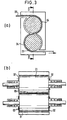
- Fig. 2(a) shows a schematic cut-away view showing in cross section the conventional construction of a vacuum sealing device of pinch roll type
- Fig. 2(b) is a cross-sectional view taken along the line A-A in Fig. 2(a), in which there is shown a pair of upper and lower rolls 01, 01 disposed rotatably in a casing 06, having a web of steel 05 pinched in the sandwiched relationship therebetween.
- the opposite end faces of these paired rolls 01, 01 are placed facing the side wall surfaces of the casing 06 having close gaps 02 therewith, in such a manner that the gaps 02 may be made as small as possible, while allowing a gas to pass therethrough, so that there may be obtained a substantial grade of vacuum within the casing 06. Also, it is arranged such that the casing 06 may be in communication with a vacuum pump, not shown, through an exhaust duct.
- Fig. 3(a) is a schematic side elevational view showing, partly cut away, a vacuum sealing station of bridle type
- Fig. 3(b) is a longitudinal cross-sectional view taken along the line B-B in Fig. 3(a), in which it is seen that the steel band 05 is threaded in the wrapped-around fashion across a pair of upper and lower rolls 01, 01, and that there are a pair of covers 04 of arcuate shape disposed in complementary relationship with the running path of the steel band on the rolls 01, 01.
- the similar problem of deposition of metals in this type sealing station may also be observed the similar problem of deposition of metals in this type sealing station to the case as noted above.
- a vacuum evaporation equipment of the kind defined by the precharacterizing features of claim 1 is known from the CH-A-288 438.
- the steel band to be deposited with evaporated metal is lead through a gap formed in a treatment chamber to which the evaporation vessel is connected and the inner surfaces of this treatment chamber are heated to a higher temperature than the evaporation temperature of the metal to be deposited in order to avoid deposition of the evaporated metal to said surfaces, thereby avoiding dripping of evaporated metal from said surfaces to the steel band.
- Metal vapor re-evaporated from the treated steel band leaving the depositing port may deposit on the inner surfaces of the vacuum vessel and drip down to the treated steel band, thereby causing a deposition layer thereon of minor quality as well as a pollution of the inner surfaces of the vacuum vessel.
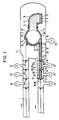
- a strip or band of steel 1 is introduced into a vacuum vessel 2 held at a relatively low pressure in sequence through vacuum block or sealing stations 31, 33 and 34 disposed in serial fashion on the inlet part of the vacuum evaporation process, and the steel band 1 is then deposited with a vapor of metal, for example, zinc which is evaporated from an evaporation vessel 4, while guided along by way of a roll 3, thereafter the steel band 1 is then redirected towards another station in line of a higher pressure in sequence through a series of vacuum sealing stations 6, 29 and 30.
- a vapor of metal for example, zinc
- the steel band 1 which was deposited with solid zinc is surrounded thoroughly by the extension of the heated inner duct 12 so that the re-evaporated vapor of zinc may effectively be prevented from depositing upon the inner duct 12 because of its heat, thus resulting in a vapor of re-evaporated zinc 8 drifting around in the interior of the inner duct 12, which would not deposit any longer upon the steel band 1 as the current component of the vapor of zinc reaches its pressure of saturated vapor P 1 at the current temperature of re-evaporation T, of the solid zinc deposited on the surface of the steel band 1.
- the evaporation vessel 4 is heated to the melting point of zinc by way of a heater 15.
- Molten zinc 14 heated up to the temperature from 430 to 580°C is then put to purge the atmospheric gas, for example, nitrogen therefrom by using a vacuum pump 21, and when the atmosphere in the vacuum vessel reaches the pressure level from 1 to 0.0001 Torr., it will then start evaporation.
- evaporated vapor of zinc 5 guided along with the channel 9, which is also a heated hood is deposited continuously onto the surface of the steel band 1 wrapped around the roll 3.
- a heater 19 extending along the inner circumference of the roll 3.
- the outer surface temperatures of the roll 3 and of the discs on the opposite ends thereof are heated to a point higher than the re-evaporation temperature of the vapor of zinc 5 at the current vapor pressure thereof, for example, 580°C at the pressure level of 1 Torr., or 230°C at the level of 0.0001 Torr.
- an arc-shaped cover member 25 to be heated by using a heater 17 on the entrance side of the steel band 1 existing around the circumference of the roll 3 and also an arc-shaped cover member 10 to be heated by the heater 17 on the outlet side of the roll 3 in such a manner that a substantial volume of zinc vapor 5 may be held from flowing out into the vacuum vessel 2 while being guided along the channel 9, and that the outer surfaces of these cover members 25 and 10 may be heated to such a temperature level as higher than the current re-evaporation temperature of the vapor of zinc 5 at the current vapor pressure thereof, for example, to the level of from 230 to 580°C under the vapor pressure of from 1 to 0.0001 Torr.
- it is ensured to such an advantage that there may occur no deposition of re-evaporated zinc vapor onto the surfaces of the roll 3 as well as the arc-shaped cover members 25 and 10, respectively.
- a similar arcuate cover member 11 having a heater 18 on the side opposite the one where the steel band 1 passes around the circumference of the roll 3 in such a manner that it may be heated by that heater 18 at a point higher than the re-evaporation temperature of the vapor of zinc 5 so that the zinc vapor may be prevented from depositing upon the inner surface of that cover member 11, accordingly.
- a gap 27 defined between this cover member 11 and the roll 3 is made as small as possible to such an extent that there is no contact between the roll 3 and the cover member 11 when installed together, so that the re-evaporated vapor of zinc 8 existing in the inner duct 12 may efficiently be prevented from espacing out into the vacuum vessel 2 owing to a possible pressure loss generated in the extension of gap 27, accordingly.
- the inner duch 12 is operatively connected at its one end to these cover members 10 and 11, while being connected at the opposite end with an expansion allowance to the sealing bar 13 of the vacuum sealing station 6, and also designed to be heated in its longitudinal extension by using a heater 20.
- the vacuum sealing stations 6 and 34 are comprised of a vacuum pump 22, the vacuum sealing stations 29 and 33 are of a vacuum pump 23, and that the vacuum sealing stations 31 and 31 are of a vacuum pump 24, respectively, each of which is evacuated to a vacuum state, and which are designed to give a stepwise reduction of pressures while passing the steel band 1 in sequence therethrough from the atmospheric pressure of 760 Torr., down to the level of 1 to 0.0001 Torr. in the interior of the vacuum vessel 2 where the steel band 1 is subjected to the vacuum evaporation operation.
- heaters in the interior of pairs of sealing rolls 28 at each of the vacuum sealing stations 6, 29, 30 for the purpose of heating the outer circumferential surfaces of these rolls to a point equal to or higherthan the re-evaporation temperature of solid zinc which was deposited upon the steel band 1 so that the vapor of re-evaporated zinc 8 is efficiently prevented from depositing upon these rolls.
- a heater not shown, in each of the sealing bars 13 for heating them to the same temperature level as that of the sealing rolls 28, so that the vapor of re-evaporated zinc 8 may well be prevented from depositing thereupon, accordingly.
- the steel band 1 finished with vacuum evaporation procedure is fed out of the roll 3, passing through the inner duct 12 heated with the heater 20 with the possibility that a re-evaporaton of solid zinc may occur from the deposited surface of the steel band 1.
- inner ducts 32 and 32' with an appropriate expansion allowance between the vacuum sealing stations 6 and 29 and between the vacuum sealing stations 29 and 30 under vacuum condition, which inner ducts are heated by way of the heater 20 for the prevention of re-evaporation of solid zinc during the equipment operation.
- the inner duct per se is formed from a sheet of stainless steel or of ordinary steel, and this duct has its outer surface insulated by using heat insulating material (not shown) so that it may be heated with a small power consumption.
- FIG. 4 there is shown a schematic side elevational view showing, partly cut-away, the general construction of the vacuum sealing station according to the present invention, while Fig. 5 is a fragmentary cross-sectional view taken along the line C-C in Fig. 4.
- the vacuum sealing stations are of pinch-roll type, and in this construction, there are provided pairs of upper and lower rolls 51, only two pairs seen in Fig. 4, mounted rotatably for carrying a band of steel 57 in the sandwiched relationship therebetween in the interior of a casing 56. It is also shown that each of such rolls 51 is designed to be hollow for incorporating a heating unit 52 therein so as to have itself heated thereby.
- Fig. 5 there is shown extending rotating shafts 51a from the opposite ends of each roll 51 outwardly through the side walls of the casing 56, and that there is provided a shaft seal 64 on the outer circumference of each of the rotating shafts 51a in the sliding contact fashion.
- a dust boot of bellow type designated at the reference numeral 63 in Fig. 5.
- side panels 61 formed from carbon or carbon fiber lining of high heat-seizure resisting property on the opposite side ends of the roll 51 in such a manner that they are held resiliently in position against the roll side ends by aid of springs 62.
- a heating unit 55 in the vicinity of the sealing bar 53 for heating the same. It is to be noted that the hollow space in the interior of the casing 56 is in intercommunication with a vacuum pump, not shown, by way of an exhaust duct 58.
- a substantial advantage achieved by the disclosed embodiments of the invention is that the undesired re-evaporation of solid zinc deposited on the product surface may efficiently be prevented from occurring, the quantity of re-evaporated zinc may be held to a minimum, and the undesired deposition of re-evaporated zinc onto the vacuum vessel, the vacuum sealing stations, or the like may well be prevented as far as possible, by virtue of the provision of the inner ducts heated to control according to the invention, thus contributing to the substantial improvement in the operating efficiency, and hence in the productivity of the entire production line.
- the undesired deposition of the metal to be evaporated onto the rolls and the gaps between the rolls and relevant cover members thereto may be efficiently prevented from occurring, by virtue of the provision of the side panels shiftable longitudinally along the axes of the rolls and mounted resiliently on the opposite sides of the rolls, and which are heated to the point higher than the re-evaporation temperature of the metal to be evaporated, thus ensuring the continued normal smooth rotating motion of the rolls, eliminating the adverse effect upon the products, and thus providing the high degree of vacuum in the components involved in the vacuum evaporation equipment, which would eventually enable a vacuum pump of as small as possible capacity to be adapted, accordingly.
Description
- The present invention relates generally to an improvement in or relating to a vacuum evaporator, and more particularly to an improved vacuum evaporation equipment for the continuous evaporation of such metals as zinc under the vacuum environment onto a band or hoop of steel products.
- It is generally known that when evaporating a certain metal such as zinc in continuation onto a band or hoop of steel product, the steel product is introduced into the evaporation chamber under the vacuum environment in sequence through the vacuum block or sealing station from the atmospheric pressure of 760 Torr. It is the general practice that the extent of vacuum provided in the atmosphere of the evaporation chamber for the evaporation operation of zinc, for instance, is set to be in an order from 1 to 0.0001 Torr. After the vacuum evaporation process is finished, the steel band is then put back under the atmospheric pressure of 760 Torr, passing through the vacuum sealing station. During this process, however, it is known that the metal such as zinc evaporated upon the steel band product would possibly be caused to be re-evaporated therefrom and then deposited onto the interior wall surfaces of the evaporation chamber and the vacuum sealing station held at the relatively low pressure levels while passing therethrough, which deposition would then grow to an excessive extent, after a long running operation. This would eventually be a substantial cause of reduction in the operating efficiency of the vacuum evaporation line, such as an extra shut-down of the whole production line for removing thus-deposited zinc from the evaporation chamber and the vacuum sealing station. In addition, the quantity of re-evaporated zinc will have to be scrapped, which is an immediate and substantial loss of material in the normal operation.
- In consideration of such circumstances as noted above, it has long been a desire that the re-evaporation of such deposition metals as zinc in the vacuum evaporation operation is prevented from occurring, and thereby improving the yield in the deposition of zinc, and that a due efficiency in the running operation of the vacuum evaporation line is to be attained from the prevention of such re-evaporation of metals to be deposited, whereby an eventual cost reduction of metal plating may be afforded, accordingly.
- In the conventional vacuum evaporation equipment, the use of the vacuum block or sealing station of such construction as typically shown in Figs. 2 and 3 is the generally known practice. Fig. 2(a) shows a schematic cut-away view showing in cross section the conventional construction of a vacuum sealing device of pinch roll type, and Fig. 2(b) is a cross-sectional view taken along the line A-A in Fig. 2(a), in which there is shown a pair of upper and
lower rolls casing 06, having a web ofsteel 05 pinched in the sandwiched relationship therebetween. It is arranged that the opposite end faces of these pairedrolls casing 06 havingclose gaps 02 therewith, in such a manner that thegaps 02 may be made as small as possible, while allowing a gas to pass therethrough, so that there may be obtained a substantial grade of vacuum within thecasing 06. Also, it is arranged such that thecasing 06 may be in communication with a vacuum pump, not shown, through an exhaust duct. - With such a general arrangement, it is noted that when the paired
rolls casing 06 expand with heat involved during the operation, theclose gaps 02 are caused to be greater, thus making it necessary to have an operating capacity of the vacuum pump for the air exhaustion increased accordingly. In order to meet this situation, therefore, it is arranged according to the conventional measure of practice that therolls casing 06 are prevented from being expanded with heat by way of the water cooling system so that theclose gaps 02 may be held to constant. - However, taking for instance the case that the
steel band 05 is vacuum evaporated with a certain metal such as zinc, this zinc once deposited on thesteel band 05 is caused to be re-evaporated therefrom in the form of zinc vapor, part of which vapor would come to deposit upon the surfaces of the pairedrolls 01 or the like held at a relatively low temperature, and also would deposit in the small gap provided between theserolls 01 and thesealing bars 03, which would then become an obstacle to the normal rotating motion of therolls 01. Also there is a possibility such that thus-deposited zinc would depart from the gap and drop onto the surface of thesteel band 05 as it passes therethrough, which would turn to be a lump of metal deposited on the steel band surface so as to be translated over to the roll surfaces of the vacuum sealing station, thus dowelled thereupon, which would very possibly give rise to the risk of damages to be rendered upon the surfaces of the steel band, as it passes therethrough during the operation. - Fig. 3(a) is a schematic side elevational view showing, partly cut away, a vacuum sealing station of bridle type, and Fig. 3(b) is a longitudinal cross-sectional view taken along the line B-B in Fig. 3(a), in which it is seen that the
steel band 05 is threaded in the wrapped-around fashion across a pair of upper andlower rolls covers 04 of arcuate shape disposed in complementary relationship with the running path of the steel band on therolls - A vacuum evaporation equipment of the kind defined by the precharacterizing features of claim 1 is known from the CH-A-288 438. The steel band to be deposited with evaporated metal is lead through a gap formed in a treatment chamber to which the evaporation vessel is connected and the inner surfaces of this treatment chamber are heated to a higher temperature than the evaporation temperature of the metal to be deposited in order to avoid deposition of the evaporated metal to said surfaces, thereby avoiding dripping of evaporated metal from said surfaces to the steel band. Metal vapor re-evaporated from the treated steel band leaving the depositing port, however, may deposit on the inner surfaces of the vacuum vessel and drip down to the treated steel band, thereby causing a deposition layer thereon of minor quality as well as a pollution of the inner surfaces of the vacuum vessel.
- It is therefore the object of the invention to improve a vacuum evaporation equipment as defined by the precharacterizing features of claim 1 so that the possibility of re-evaporation of metal once deposited to the steel band therefrom in order to avoid pollution of the vacuum vessel and in order to produce high quality depositions on the steel band.
- This object is attained by the characterizing features of claim 1. The subclaims are directed to advantageous developments of the invention.
- The principle, nature and details of the present invention will, as well as advantages thereof, become more apparent from the following detailed description by way of a preferred embodiment of the invention, when read in conjunction with the accompanying drawings, in which like parts are designated at like reference numerals.
- In the drawings:
- Fig. 1 is a schematic general view showing, in longitudinal cross-section, the construction of a vacuum evaporation equipment by way of a preferred embodiment of the present invention;
- Fig. 2(a) is a schematic side elevational view showing, in cross-section, the general construction of a vacuum sealing station of pinch-roll type;
- Fig. 2(b) is a schematic cross-sectional view taken along the line A-A in Fig. 2(b);
- Fig. 3(a) is a schematic side elevational view showing, in cross-section, the construction of a vacuum sealing station of bridle-roll type;
- Fig. 3(b) is a schematic cross-sectional view taken along the line B-B in Fig. 3(a);
- Fig. 4 is a fragmentary schematic view showing, partly cut-away, the construction of a vacuum sealing device according to the present invention; and
- Fig. 5 is a fragmentary cross-sectional view taken along the line C-C in Fig. 4.
- The present invention will now be described in detail by way of example on a preferred embodiment thereof in conjunction with the accompanying drawings, as follows.
- Now, referring to Fig. 1, there is shown, by way of a preferred embodiment of the present invention, the general construction of a vacuum evaporation equipment. In Fig. 1, it is seen that a strip or band of steel 1 is introduced into a vacuum vessel 2 held at a relatively low pressure in sequence through vacuum block or
sealing stations evaporation vessel 4, while guided along by way of aroll 3, thereafter the steel band 1 is then redirected towards another station in line of a higher pressure in sequence through a series of vacuum sealing stations 6, 29 and 30. - It is known that zinc now in the state of solid deposited upon the surface of the steel band 1 is generally likely to be re-evaporated in an environment of a relatively low pressure or vacuum. This is the phenomenon called re-evaporation of metals in the general vacuum evaporation process. This specific trend of re-evaporation would generally decrease as the pressure of an atmosphere grows higher, and it is actually questionable in the engineering of such vacuum evaporation process with the extent of vacuum ranging from 10 to 20 Torr. It is generally notable that there may be observed a greater extent of re-evaporation especially on the part in the evaporation line that is held at a relatively low pressure.
- It is commonly known to those skilled in the art that solid zinc will continue to re-evaporate from the deposited surface of the steel band 1 till it reaches its pressure of saturated vapor prevailing at the current temperature of solid zinc. In this connection, therefore, when such devices which the steel band 1 deposited with zinc passes through, for example, a series of vacuum sealing stations 6, 29, 30 on the outlet side of the vacuum vessel 2, and a middle duct 7 connecting each of these stations are held at the normal temperature, the then re-evaporated vapor of
zinc 8 is now to be deposited onto each of such devices. More specifically, this re-evaporation may continuously occur from the surface of solid zinc deposited on the steel band 1 onto such devices as noted above, upon which such deposition is observed eventually. Thus-deposited solid zinc should be removed at a regular interval, which would naturally result in an obstruction against the productivity of the vacuum evaporation line, accordingly. - There is deposited a vapor of zinc 5 upon the steel band 1 in the process where the vapor is introduced toward the
roll 3 along with a channel 9, which is the completion of zinc deposition step, thereafter the steel band 1 is carried outwardly departing from the circumference of theroll 3. There is seen provided aninner duct 12, which is heated by way of a heater, extending in the tangential manner from a set ofarcuate cover members roll 3, and connected with a series ofsealing bars 13 in the vacuum sealing station 6. In this connection, it is specifically arranged that the steel band 1 which was deposited with solid zinc is surrounded thoroughly by the extension of the heatedinner duct 12 so that the re-evaporated vapor of zinc may effectively be prevented from depositing upon theinner duct 12 because of its heat, thus resulting in a vapor of re-evaporatedzinc 8 drifting around in the interior of theinner duct 12, which would not deposit any longer upon the steel band 1 as the current component of the vapor of zinc reaches its pressure of saturated vapor P1 at the current temperature of re-evaporation T, of the solid zinc deposited on the surface of the steel band 1. Upon the reach at the pressure of saturated vapor P1, even if a larger extension of the steel band 1 finished with vacuum evaporation will continue to pass through theinner duct 12, as the re-evaporation of solid zinc is effectively held from occurring, a substantial improvement in the yield of zinc during the evaporation operation may well be attained, accordingly. In addition, by virtue of the efficient control in restraint of the vapor ofre-evaporated zinc 8, there may be attained the substantial improvement in the operability of the entire evaporation line with less frequent shut-downs, thus resulting in an increase in the productivity of the entire line, after all. - Referring more specifically to the construction shown in Fig. 1 by way of the preferred embodiment of the invention, the
evaporation vessel 4 is heated to the melting point of zinc by way of aheater 15. Moltenzinc 14 heated up to the temperature from 430 to 580°C is then put to purge the atmospheric gas, for example, nitrogen therefrom by using avacuum pump 21, and when the atmosphere in the vacuum vessel reaches the pressure level from 1 to 0.0001 Torr., it will then start evaporation. Thus evaporated vapor of zinc 5 guided along with the channel 9, which is also a heated hood, is deposited continuously onto the surface of the steel band 1 wrapped around theroll 3. There is provided aheater 19 extending along the inner circumference of theroll 3. With this arrangement, the outer surface temperatures of theroll 3 and of the discs on the opposite ends thereof are heated to a point higher than the re-evaporation temperature of the vapor of zinc 5 at the current vapor pressure thereof, for example, 580°C at the pressure level of 1 Torr., or 230°C at the level of 0.0001 Torr. - There are provided an arc-
shaped cover member 25 to be heated by using aheater 17 on the entrance side of the steel band 1 existing around the circumference of theroll 3 and also an arc-shaped cover member 10 to be heated by theheater 17 on the outlet side of theroll 3 in such a manner that a substantial volume of zinc vapor 5 may be held from flowing out into the vacuum vessel 2 while being guided along the channel 9, and that the outer surfaces of thesecover members roll 3 as well as the arc-shaped cover members - It is also arranged there there is defined an as small as
possible gap 26 between theroll 3 and the arc-shaped cover members shaped cover members gap 26 around the outer circumferential surface of theroll 3 as allowed by the dimensions of the equipment so that the vapor of zinc 5 may efficiently be held from escaping into the areas of the vacuum vessel 2 and theinner duct 12 owing to a possible loss of pressure during the passage along with the extension ofgap 26. - Also, there is provided a similar
arcuate cover member 11 having aheater 18 on the side opposite the one where the steel band 1 passes around the circumference of theroll 3 in such a manner that it may be heated by thatheater 18 at a point higher than the re-evaporation temperature of the vapor of zinc 5 so that the zinc vapor may be prevented from depositing upon the inner surface of thatcover member 11, accordingly. It is also notable that agap 27 defined between thiscover member 11 and theroll 3 is made as small as possible to such an extent that there is no contact between theroll 3 and thecover member 11 when installed together, so that the re-evaporated vapor ofzinc 8 existing in theinner duct 12 may efficiently be prevented from espacing out into the vacuum vessel 2 owing to a possible pressure loss generated in the extension ofgap 27, accordingly. - Also, it is arranged such that the
inner duch 12 is operatively connected at its one end to thesecover members sealing bar 13 of the vacuum sealing station 6, and also designed to be heated in its longitudinal extension by using aheater 20. - It is noted that the
vacuum sealing stations 6 and 34 are comprised of avacuum pump 22, thevacuum sealing stations 29 and 33 are of avacuum pump 23, and that thevacuum sealing stations vacuum pump 24, respectively, each of which is evacuated to a vacuum state, and which are designed to give a stepwise reduction of pressures while passing the steel band 1 in sequence therethrough from the atmospheric pressure of 760 Torr., down to the level of 1 to 0.0001 Torr. in the interior of the vacuum vessel 2 where the steel band 1 is subjected to the vacuum evaporation operation. And, as the steel band 1 passes in the stroke turning out of the vacuum evaporation process through the stages of such vacuum sealing stations with stepwise increasing level of pressures up to the atmospheric pressure of 760 Torr., thus all through with the vacuum evaporation procedures in the processing line. - There are provided heaters (not shown) in the interior of pairs of sealing rolls 28 at each of the vacuum sealing stations 6, 29, 30 for the purpose of heating the outer circumferential surfaces of these rolls to a point equal to or higherthan the re-evaporation temperature of solid zinc which was deposited upon the steel band 1 so that the vapor of
re-evaporated zinc 8 is efficiently prevented from depositing upon these rolls. Also provided is a heater, not shown, in each of the sealing bars 13 for heating them to the same temperature level as that of the sealing rolls 28, so that the vapor ofre-evaporated zinc 8 may well be prevented from depositing thereupon, accordingly. - Now, referring to the operation of the present vacuum evaporation equipment according to the present invention, it is noted that the steel band 1 finished with vacuum evaporation procedure is fed out of the
roll 3, passing through theinner duct 12 heated with theheater 20 with the possibility that a re-evaporaton of solid zinc may occur from the deposited surface of the steel band 1. There exist nitrogen (N2) and a vapor ofre-evaporated zinc 8 dispersed commonly in the interior of theinner duct 12. Under such a condition, there may continue re-evaporation of solid zinc from the surface of the steel band 1, till the current partial pressure of zinc vapor from the re-evaporation ofzinc 8 reaches the pressure of saturated vapor P, of zinc at the re-evaporation temperature T, of solid zinc deposited on the surface of the steel band 1. - In this case, however, with the temperature of the surface of the
inner duct 12 where the steel band 1 faces while passing therethrough heated by theheater 20 to a point equal to or higher than the current re-evaporation temperature of solid zinc existing on the steel band 1, it is notable that there is no deposition of the vapor ofre-evaporated zinc 8 onto the inner wall surface of theinner duct 12, at all. - In this manner, it is eventually ensured with such an advantageous result that no deposition of zinc is observed upon the surfaces of the steel band 1 while passing the vacuum vessel and through the sequence of vacuum sealing stations 6,29 and 30, thus making it feasible in practice to obtain the continued vacuum evaporation process free from deposition of zinc throughout the entire vacuum evaporation line, thus providing the flawless product of evaporation, accordingly.
- On the other hand, after the partial pressure of the vapor of
re-evaporated zinc 8 reached the current pressure of saturated zinc vapor P, prevailing at the re-evaporation temperature T, of solid zinc existing on the surface of the steel band 1 within theinner duct 12, there will not occur any further re-evaporation of zinc, thus contributing to a substantial reduction in the waste zinc vapor, otherwise lost in the re-evaporation of solid zinc deposited on the steel band 1 at all. - There are also provided
inner ducts 32 and 32' with an appropriate expansion allowance between the vacuum sealing stations 6 and 29 and between the vacuum sealing stations 29 and 30 under vacuum condition, which inner ducts are heated by way of theheater 20 for the prevention of re-evaporation of solid zinc during the equipment operation. - It is known that the extent of reduced pressure or degree of vacuum that requires the due control of re-evaporation in the process is up to approx. 20 Torr. or so, and in this connection, it is essential that there is extended the inner duct from the vacuum vessel 2 to the vacuum sealing stations under the reduced pressure of approx. 20 Torr., which inner duct is to be heated by way of a heating device incorporated. The inner duct per se is formed from a sheet of stainless steel or of ordinary steel, and this duct has its outer surface insulated by using heat insulating material (not shown) so that it may be heated with a small power consumption.
- When a total pressure nitrogen gas (N2) and the vapor
re-evaporated zinc 8 existing in the inside of theinner duct 12 is not equal with the pressure level of atmosphere in the vacuum vessel 2, there may occur evaporation ofmolten zinc 14 in theevaporation vessel 4, which would then block the vacuum evaporation onto the steel band 1. In consideration of such condition, there are provided small openings (not shown) in theinner ducts re-evaporated zinc 8 in theinner ducts - In this construction as noted above, it is to be noted that there is only an as small as negligible quantity of vapor of
re-evaporated zinc 8 dispersing outwardly from such openings provided in the inner ducts. - Next, referring to Fig. 4, there is shown a schematic side elevational view showing, partly cut-away, the general construction of the vacuum sealing station according to the present invention, while Fig. 5 is a fragmentary cross-sectional view taken along the line C-C in Fig. 4.
- As seen in these figures, the vacuum sealing stations are of pinch-roll type, and in this construction, there are provided pairs of upper and
lower rolls 51, only two pairs seen in Fig. 4, mounted rotatably for carrying a band ofsteel 57 in the sandwiched relationship therebetween in the interior of acasing 56. It is also shown that each ofsuch rolls 51 is designed to be hollow for incorporating aheating unit 52 therein so as to have itself heated thereby. In Fig. 5, there is shown extendingrotating shafts 51a from the opposite ends of eachroll 51 outwardly through the side walls of thecasing 56, and that there is provided ashaft seal 64 on the outer circumference of each of therotating shafts 51a in the sliding contact fashion. There is also shown a dust boot of bellow type designated at thereference numeral 63 in Fig. 5. - Also, as shown in Fig. 5, there are provided
side panels 61 formed from carbon or carbon fiber lining of high heat-seizure resisting property on the opposite side ends of theroll 51 in such a manner that they are held resiliently in position against the roll side ends by aid ofsprings 62. In connection with this construction, there are formedclose gaps lower rolls side panel 61 and the inner circumference of thecasing 56, respectively. - On the other hand, there is provided a sealing
bar 53 with aclose gap 54 with each of therolls 51 in such a manner that it can be shifted slidably along the direction of forward travelling motion of the steel band 57 (shown by an arrow in Fig. 4), so that thegap 54 may be adjusted by shifting the location of the sealingbar 53 in the longitudinal direction, as desired. There is also shown provided aheating unit 55 in the vicinity of the sealingbar 53 for heating the same. It is to be noted that the hollow space in the interior of thecasing 56 is in intercommunication with a vacuum pump, not shown, by way of anexhaust duct 58. - With such construction, it is noted that when the sealing rolls 51 and the sealing bars 53 are heated by using the
heating units steel band 57, an undesired deposition of metal to be evaporated, otherwise observed at the sealing rolls 51 and the sealing bars 53, as well as at thegap 54, may efficiently be prevented from occurring, thus resulting in an ensured smooth rotating motion of therolls 51, and eliminating the risks of damages or flaws on the finished surface of thesteel band 57, and thus ensuring the eventual excellent quality of the products. - In addition, by virtue of the employment of the
side panels 61 mounted constantly with resiliency against the side walls of therolls 51, it is now possible in practice to have an optimal gap that may constantly be maintained to a minimum between the sealing rolls 51 and thecasing 56 irrespectively of the current extent of heat expansion of these members involved, and with such an advantageous effect, it is practicably possible to apply a vacuum pump of a smallest possible capacity for the same scale of a production line, thus contributing to a substantial curtailment in the initial investment and the subsequent running exhaust operation cost of a vacuum evaporation plant, accordingly. - The present invention was fully explained hereinbefore, and a further review will now be given by way of a typical experiment of the invention, as follows.
- There was conducted a series of evaporation works on the equipment shown in Fig. 1 under the following conditions.
- Specification of Steel Band:
- 0.6 mm thickx300 mm wide normal steel sheet Velocity of Steel Sheet:
- 15 m/min.
- Temp. of Steel Sheet:
- 250°C, before vacuum evaporation operation
- Vacuum Operating Conditions:
- Pressure of Vacuum Vessel:
- 0.07 Torr.
- Pressure of Vacuum Seal 6:
- 1.00 Torr.
- Pressure of Vacuum Seal 29:
- 10.00 Torr.
- Pressure of Vacuum Seal 30:
- 70.00 Torr.
- Temp. of Inner Walls of Inner
-
Ducts - 300°C.
- Temp. of Molten Zinc 14:
- 480°C.
- Temp. of Inner Walls of Arc-shaped
Cover Members - 480°C.
- Temp. of Outer Surface of Roll 3:
- 480°C.
- Surface Temp. of Seal Roll 28 and Sealing Bar 13:
- 300°C.
- Thickness of Deposited Metal:
- 40 gr/m2.
- As the result of experiments of vacuum evaporation operation under such conditions as raised above, no deposition of re-evaporated zinc was observed on the inner wall surfaces of the
inner ducts inner ducts inner ducts - There was either observed no deposition of zinc upon the surfaces of the sealing rolls and sealing bars in the evaporation test plant in practice of the present invention. Also, it was confirmed that the sealing performance of these sealing stations exhibited substantially higher than the case wherein the rolls are cooled off with cooling water.
- Now, according to such a unique construction of the vacuum evaporation equipment as adaptable to the general vacuum evaporation line as typically shown by way of the preferred embodiment of the present invention, a substantial advantage achieved by the disclosed embodiments of the invention is that the undesired re-evaporation of solid zinc deposited on the product surface may efficiently be prevented from occurring, the quantity of re-evaporated zinc may be held to a minimum, and the undesired deposition of re-evaporated zinc onto the vacuum vessel, the vacuum sealing stations, or the like may well be prevented as far as possible, by virtue of the provision of the inner ducts heated to control according to the invention, thus contributing to the substantial improvement in the operating efficiency, and hence in the productivity of the entire production line.
- Also, it is the advantageous effect afforded by the present invention that the undesired deposition of the metal to be evaporated onto the rolls and the gaps between the rolls and relevant cover members thereto may be efficiently prevented from occurring, by virtue of the provision of the side panels shiftable longitudinally along the axes of the rolls and mounted resiliently on the opposite sides of the rolls, and which are heated to the point higher than the re-evaporation temperature of the metal to be evaporated, thus ensuring the continued normal smooth rotating motion of the rolls, eliminating the adverse effect upon the products, and thus providing the high degree of vacuum in the components involved in the vacuum evaporation equipment, which would eventually enable a vacuum pump of as small as possible capacity to be adapted, accordingly.
Claims (5)
Applications Claiming Priority (4)
| Application Number | Priority Date | Filing Date | Title |
|---|---|---|---|
| JP5114184A JPS60197876A (en) | 1984-03-19 | 1984-03-19 | Vacuum deposition device |
| JP51141/84 | 1984-03-19 | ||
| JP59086169A JPS60234964A (en) | 1984-05-01 | 1984-05-01 | Vacuum sealing device |
| JP86169/84 | 1984-05-01 |
Publications (3)
| Publication Number | Publication Date |
|---|---|
| EP0155643A2 EP0155643A2 (en) | 1985-09-25 |
| EP0155643A3 EP0155643A3 (en) | 1987-11-25 |
| EP0155643B1 true EP0155643B1 (en) | 1990-06-27 |
Family
ID=26391672
Family Applications (1)
| Application Number | Title | Priority Date | Filing Date |
|---|---|---|---|
| EP85102965A Expired - Lifetime EP0155643B1 (en) | 1984-03-19 | 1985-03-14 | Vacuum evaporation equipment |
Country Status (6)
| Country | Link |
|---|---|
| US (1) | US4649860A (en) |
| EP (1) | EP0155643B1 (en) |
| KR (1) | KR890004043B1 (en) |
| AU (1) | AU553239B2 (en) |
| CA (1) | CA1233016A (en) |
| DE (2) | DE3578437D1 (en) |
Families Citing this family (11)
| Publication number | Priority date | Publication date | Assignee | Title |
|---|---|---|---|---|
| US4829189A (en) * | 1986-07-18 | 1989-05-09 | Sando Iron Works Co., Ltd. | Apparatus for low-temperature plasma treatment of sheet material |
| GB2216904B (en) * | 1988-02-09 | 1992-04-29 | Nisshin Steel Co Ltd | Process for preparing alloyed-zinc-plated titanium-killed steel sheet having excellent deep-drawability |
| DE59908893D1 (en) * | 1998-03-27 | 2004-04-22 | Empa | VACUUM BAND COATING LINE |
| US9017480B2 (en) * | 2006-04-06 | 2015-04-28 | First Solar, Inc. | System and method for transport |
| US20100159132A1 (en) * | 2008-12-18 | 2010-06-24 | Veeco Instruments, Inc. | Linear Deposition Source |
| WO2011065998A1 (en) * | 2008-12-18 | 2011-06-03 | Veeco Instruments Inc. | Linear deposition source |
| WO2011065999A1 (en) * | 2008-12-18 | 2011-06-03 | Veeco Instruments Inc. | Linear deposition source |
| KR101180246B1 (en) * | 2009-12-24 | 2012-09-05 | 주식회사 포스코 | Strip Passing Apparatus and Apparatus for Treating Surface of The Strip using The Same, and Method for Treating Surface of The Strip |
| FR2992978B1 (en) * | 2012-07-06 | 2014-07-11 | Commissariat Energie Atomique | DEVICE FOR GENERATING TARGETS BASED ON HYDROGEN AND / OR SOLID DEUTERIUM |
| UA117592C2 (en) | 2013-08-01 | 2018-08-27 | Арселорміттал | PAINTED GALVANIZED STEEL SHEET AND METHOD OF MANUFACTURING |
| JP6801887B2 (en) * | 2018-10-18 | 2020-12-16 | 株式会社クリエイティブコーティングス | Film deposition equipment |
Family Cites Families (7)
| Publication number | Priority date | Publication date | Assignee | Title |
|---|---|---|---|---|
| CH288438A (en) * | 1950-10-23 | 1953-01-31 | Alois Dr Vogt | Method for applying metal coatings to elongated work items, as well as device for carrying out the method. |
| US3278331A (en) * | 1965-07-26 | 1966-10-11 | Pennsalt Chemicals Corp | Process for coating steel with zinc |
| GB1355798A (en) * | 1970-05-28 | 1974-06-05 | Bekaert Sa Nv | Process for the deposition of metal coatings on to metal elements and on apparatus therefor |
| US3989862A (en) * | 1970-10-13 | 1976-11-02 | Jones & Laughlin Steel Corporation | Method and apparatus for vapor-depositing coatings on substrates |
| US3788877A (en) * | 1972-07-20 | 1974-01-29 | Steel Corp | Method for producing adherent,ductile zinc coating on ferrous substrates by vacuum deposition |
| JPS54110143A (en) * | 1978-02-17 | 1979-08-29 | Mitsubishi Heavy Ind Ltd | Zinc vacuum plating method and equipment |
| JPS57152465A (en) * | 1981-03-17 | 1982-09-20 | Mitsubishi Heavy Ind Ltd | Vacuum depositing method for zinc |
-
1985
- 1985-03-14 DE DE8585102965T patent/DE3578437D1/en not_active Expired - Lifetime
- 1985-03-14 EP EP85102965A patent/EP0155643B1/en not_active Expired - Lifetime
- 1985-03-14 DE DE198585102965T patent/DE155643T1/en active Pending
- 1985-03-15 AU AU40012/85A patent/AU553239B2/en not_active Ceased
- 1985-03-19 US US06/713,743 patent/US4649860A/en not_active Expired - Lifetime
- 1985-03-19 CA CA000476897A patent/CA1233016A/en not_active Expired
- 1985-03-19 KR KR1019850001760A patent/KR890004043B1/en not_active IP Right Cessation
Also Published As
| Publication number | Publication date |
|---|---|
| EP0155643A2 (en) | 1985-09-25 |
| KR850006551A (en) | 1985-10-14 |
| DE155643T1 (en) | 1986-01-30 |
| CA1233016A (en) | 1988-02-23 |
| AU553239B2 (en) | 1986-07-10 |
| EP0155643A3 (en) | 1987-11-25 |
| AU4001285A (en) | 1985-09-26 |
| DE3578437D1 (en) | 1990-08-02 |
| KR890004043B1 (en) | 1989-10-18 |
| US4649860A (en) | 1987-03-17 |
Similar Documents
| Publication | Publication Date | Title |
|---|---|---|
| EP0155643B1 (en) | Vacuum evaporation equipment | |
| US4934444A (en) | Device and method for cooling rolls | |
| US4552092A (en) | Vacuum vapor deposition system | |
| US3868106A (en) | Vacuum chamber seal | |
| EP0995807B1 (en) | Sealing apparatus in continuous heat-treatment furnace and sealing method | |
| US4537243A (en) | Method of and apparatus for steam preheating endless flexible casting belt | |
| US4242154A (en) | Preheat and cleaning system | |
| US4681536A (en) | Charging sluice for annealing oven | |
| US2199472A (en) | Method and apparatus for annealing strip | |
| CA1182618A (en) | Steam preheating the endless flexible casting belt in a continuous casting machine | |
| JPS6353262B2 (en) | ||
| JPS5938382A (en) | Vacuum deposition device | |
| JPH07116580B2 (en) | Alloying furnace with holding zone with cooling function | |
| US4524821A (en) | Apparatus to improve casting band life | |
| US5431755A (en) | Method of and arrangement for thermal treatment of continuously moving metal bands | |
| JPS624865A (en) | Sealing device for vacuum treating apparatus | |
| RU2006100290A (en) | METHOD AND INSTALLATION FOR COOLING A METAL TAPE WHEN IT IS PRE-STRESSED | |
| JPS63238273A (en) | Heat pipe roll | |
| GB2085779A (en) | Steam preheating and endless flexible casting belt in a continuous casting machine | |
| JP3757402B2 (en) | Vacuum seal device | |
| JPS63179066A (en) | Winding roll | |
| JPS63179064A (en) | Winding roll | |
| JPS63179063A (en) | Winding roll | |
| JPH01184270A (en) | Vacuum deposition device | |
| JPS63179065A (en) | Winding roll |
Legal Events
| Date | Code | Title | Description |
|---|---|---|---|
| PUAI | Public reference made under article 153(3) epc to a published international application that has entered the european phase |
Free format text: ORIGINAL CODE: 0009012 |
|
| 17P | Request for examination filed |
Effective date: 19850411 |
|
| AK | Designated contracting states |
Designated state(s): BE DE FR GB |
|
| EL | Fr: translation of claims filed | ||
| DET | De: translation of patent claims | ||
| PUAL | Search report despatched |
Free format text: ORIGINAL CODE: 0009013 |
|
| AK | Designated contracting states |
Kind code of ref document: A3 Designated state(s): BE DE FR GB |
|
| 17Q | First examination report despatched |
Effective date: 19890320 |
|
| GRAA | (expected) grant |
Free format text: ORIGINAL CODE: 0009210 |
|
| AK | Designated contracting states |
Kind code of ref document: B1 Designated state(s): BE DE FR GB |
|
| ET | Fr: translation filed | ||
| REF | Corresponds to: |
Ref document number: 3578437 Country of ref document: DE Date of ref document: 19900802 |
|
| PLBE | No opposition filed within time limit |
Free format text: ORIGINAL CODE: 0009261 |
|
| STAA | Information on the status of an ep patent application or granted ep patent |
Free format text: STATUS: NO OPPOSITION FILED WITHIN TIME LIMIT |
|
| 26N | No opposition filed | ||
| PGFP | Annual fee paid to national office [announced via postgrant information from national office to epo] |
Ref country code: GB Payment date: 19970305 Year of fee payment: 13 |
|
| PGFP | Annual fee paid to national office [announced via postgrant information from national office to epo] |
Ref country code: FR Payment date: 19970313 Year of fee payment: 13 |
|
| PGFP | Annual fee paid to national office [announced via postgrant information from national office to epo] |
Ref country code: DE Payment date: 19970321 Year of fee payment: 13 |
|
| PGFP | Annual fee paid to national office [announced via postgrant information from national office to epo] |
Ref country code: BE Payment date: 19970521 Year of fee payment: 13 |
|
| PG25 | Lapsed in a contracting state [announced via postgrant information from national office to epo] |
Ref country code: GB Free format text: LAPSE BECAUSE OF NON-PAYMENT OF DUE FEES Effective date: 19980314 |
|
| PG25 | Lapsed in a contracting state [announced via postgrant information from national office to epo] |
Ref country code: FR Free format text: THE PATENT HAS BEEN ANNULLED BY A DECISION OF A NATIONAL AUTHORITY Effective date: 19980331 Ref country code: BE Free format text: LAPSE BECAUSE OF NON-PAYMENT OF DUE FEES Effective date: 19980331 |
|
| BERE | Be: lapsed |
Owner name: NISSHIN STEEL CO. LTD Effective date: 19980331 Owner name: MITSUBISHI JUKOGYO K.K. Effective date: 19980331 |
|
| GBPC | Gb: european patent ceased through non-payment of renewal fee |
Effective date: 19980314 |
|
| PG25 | Lapsed in a contracting state [announced via postgrant information from national office to epo] |
Ref country code: DE Free format text: LAPSE BECAUSE OF NON-PAYMENT OF DUE FEES Effective date: 19981201 |
|
| REG | Reference to a national code |
Ref country code: FR Ref legal event code: ST |