EP0154134B1 - Thermostatregelung - Google Patents
Thermostatregelung Download PDFInfo
- Publication number
- EP0154134B1 EP0154134B1 EP85100618A EP85100618A EP0154134B1 EP 0154134 B1 EP0154134 B1 EP 0154134B1 EP 85100618 A EP85100618 A EP 85100618A EP 85100618 A EP85100618 A EP 85100618A EP 0154134 B1 EP0154134 B1 EP 0154134B1
- Authority
- EP
- European Patent Office
- Prior art keywords
- lubricant
- heat exchanger
- pass duct
- temperature
- cage
- Prior art date
- Legal status (The legal status is an assumption and is not a legal conclusion. Google has not performed a legal analysis and makes no representation as to the accuracy of the status listed.)
- Expired
Links
Images
Classifications
-
- F—MECHANICAL ENGINEERING; LIGHTING; HEATING; WEAPONS; BLASTING
- F01—MACHINES OR ENGINES IN GENERAL; ENGINE PLANTS IN GENERAL; STEAM ENGINES
- F01M—LUBRICATING OF MACHINES OR ENGINES IN GENERAL; LUBRICATING INTERNAL COMBUSTION ENGINES; CRANKCASE VENTILATING
- F01M5/00—Heating, cooling, or controlling temperature of lubricant; Lubrication means facilitating engine starting
- F01M5/005—Controlling temperature of lubricant
- F01M5/007—Thermostatic control
Definitions
- the invention relates to a method for regulating the lubricant flow and an internal combustion engine equipped with a corresponding device according to the preambles of the independent claims.
- the lubricant used for an internal combustion engine changes its viscosity and consequently its lubricating function due to temperature changes. For example, with a cold internal combustion engine and cold lubricant, its viscosity is high, while with a high lubricant temperature the viscosity becomes lower, so that the lubricating effect decreases significantly.
- control devices are used which keep the temperature of the lubricant and consequently the lubricating effect in an optimum operating range given by the viscosity.
- a disadvantage of a generic method for regulating the lubricant temperature is that in the case of a cold internal combustion engine, the cold lubricant is drawn from the lubricant sump by a lubricant pump and is fed directly to the bearing points of the internal combustion engine via a bypass line, bypassing a heat exchanger (DE-A 1 932 908) .
- the lubricant must first be warmed up by brushing over slowly warming internal combustion engine components before it comes into the range of its good lubricating properties due to the viscosity.
- US-A 2 483 291 shows a control system which has a thermostatic ring coil which can move a valve body in a variety of positions.
- FR-A 2 510 707 shows a thermostat structure of the generic type for independent claim 2, the control characteristic of which essentially corresponds to that of DE-A 1 932 908.
- the valve body closes off the inflow of the lubricant to the bypass line bypassing the heat exchanger on a seat ring connected to the valve housing in the manner of a valve plate.
- the lubricant therefore flows through the rapidly warming heat exchanger, the heat exchanger being designed with a correspondingly strong component to accommodate the pressure surges that occur with cold lubricant. Only when the thermostat is warmed up so far that it lifts the valve body it controls and thus the flange-like extension from the seat ring, does the lubricant pass through an indentation in the valve body into the bypass line bypassing the heat exchanger.
- the lubricant has now been heated to such an extent that it does not require any further heat or cooling. If the lubricant reaches higher temperatures as a result of the load on the internal combustion engine, the thermostat pushes the valve body further out of its basic position and the indentation of the valve body, which continuously widens up to a guide part, increasingly reduces the flow of lubricant into the bypass line. Above a certain limit temperature, for example 80 ° C., the guide part of the valve body, which corresponds with its outer diameter to the inner diameter of the aforementioned seat ring, completely closes the inflow into the bypass line.
- a certain limit temperature for example 80 ° C.
- the plunger cooperating with the thermostat is supported on an adjustable plug screwed into the valve housing.
- the diameter of the sealing plug is so large that the thermostat, valve body, spring and seat ring can be assembled and disassembled through the opening in the housing.
- the sealing plug is provided with a guide cylinder in which the guide part of the valve body can be moved.
- the support ring is advantageously made in one piece with the plug.
- a liquid heat carrier flows through the heat exchanger.
- this can be the corresponding coolant. Since the coolant reaches its operating temperature much faster than the lubricant, but it is lower than that of the lubricant, the coolant can be used for both heating and cooling the lubricant.
- a gaseous heat transfer medium flows through the heat exchanger.
- this can be, for example, the cooling air.
- internal combustion engine exhaust gases can be passed directly through the heat exchanger to heat the lubricant, or preheated cooling air can be passed indirectly into the lubricant heat exchanger via a further heat exchanger.
- the air flowing through the heat exchanger can be infinitely variable in a quantity controlled by a thermostat control heated air and thus its temperature can be regulated.
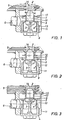
- the thermostat 1 is in its initial position when the lubricant is cold.
- the valve body 4 is pressed by a spring 2, which is supported in a housing, with its flange-like extension 10 onto a seat ring 7 fastened in the housing 11. Furthermore, the valve body 4 is supported in the area of its continuously increasing surface 8 on a shoulder of the thermostat 1 inserted into the valve body 4.
- the basic vote i.e. the extended length of the plunger 3 in this operating state is adjusted so that the thermostat 1 just touches the continuously increasing surface 8 of the valve body 4.
- the depth of insertion of the thermostat control device into the housing 11 can be changed with the adjustable sealing plug 9.
- FIG. 3 the steady state with hot lubricant is shown.
- the thermostat 1 has shifted so far on the tappet 3 that the guide part 13 of the valve body 4 projects with its outer surface exactly into the seat ring 7 and thus prevents the inflow of lubricant to the bypass line 6. This ensures that when the lubricant is hot, it in turn flows solely through the heat exchanger 5 to the internal combustion engine.
Landscapes
- Engineering & Computer Science (AREA)
- Mechanical Engineering (AREA)
- General Engineering & Computer Science (AREA)
- Temperature-Responsive Valves (AREA)
- Lubrication Of Internal Combustion Engines (AREA)
- Glass Compositions (AREA)
- Surgical Instruments (AREA)
- Input Circuits Of Receivers And Coupling Of Receivers And Audio Equipment (AREA)
- Lubricants (AREA)
- Sampling And Sample Adjustment (AREA)
- Crystals, And After-Treatments Of Crystals (AREA)
Description
- Die Erfindung bezieht sich auf ein Verfahren zur Regelung des Schmierstoffflusses und eine mit einer entsprechenden Vorrichtung ausgestatteten Brennkraftmaschine gemäß den Oberbegriffen der unabhängigen Patentansprüche.
- Es ist allgemein bekannt, daß der für eine Brennkraftmaschine verwendete Schmierstoff durch Temperaturänderungen seine Viskosität und demzufolge seine Schmierfunktion ändert. So ist bei kalter Brennkraftmaschine und kaltem Schmierstoff dessen Viskosität hoch, während bei hoher Schmierstofftemperatur die Viskosität geringer wird, so daß die Schmierwirkung deutlich abnimmt.
- Aus diesem Grunde werden Steuereinrichtungen eingesetzt, die die Temperatur des Schmierstoffs und demzufolge die Schmierwirkung in einem durch die Viskosität gegebenen optimalen Betriebsbereich halten.
- Nachteilig an einem gattungsgemäßen Verfahren zur Regelung der Schmierstofftemperatur ist es, daß bei kalter Brennkraftmaschine der kalte Schmierstoff von einer Schmierstoffpumpe aus dem Schmierstoffsumpf angesaugt wird und über eine Bypaßleitung unter Umgehung eines Wärmetauschers den Lagerstellen der Brennkraftmaschine direkt zugeführt wird (DE-A 1 932 908). Demzufolge muß der Schmierstoff erst durch ein Vorbeistreichen an sich langsam erwärmenden Brennkraftmaschinenbauteilen angewärmt werden, bevor er in den Bereich seiner durch die Viskosität bedingten guten Schmiereigenschaften kommt.
- Aus der US-A 4 398 662 ist ein Steuersystem bekannt, das aus mehreren Thermostaten und Ventilkörpern besteht und insgesamt kompliziert und folglich störanfällig aufgebaut ist. Bei kaltem Schmierstoff wird dieser zumindest teilweise der Brennkraftmaschine direkt zugeführt, so daß der Schmierstoff auch hier nur langsam angewärmt wird.
- Die US-A 2 483 291 zeigt ein Steursystem, das eine thermostatisch wirkende Ringspule aufweist, die einen Ventilkörper in eine Vielzahl von Stellungen bewegen kann.
- Die FR-A 2 510 707 zeigt einen zu dem unabhängigen Patentanspruch 2 gattungsgemäßen Thermostataufbau, dessen Steuercharakteristik im wesentlichen der der DE-A 1 932 908 entspricht.
- Aufgabe der vorliegenden Erfindung ist es daher, ein Verfahren zur Regelung des Schmierstoffflusses anzugeben und eine entsprechend ausgerüstete Brennkraftmaschine bereitzustellen, womit eine gegenüber herkömmlichen Steuereinrichtungen kürzere Warmlaufphase für die Brennkraftmaschine ermöglicht wird.
- Der Ventilkörper verschließt im Ausgangszustand des Systems bei kalter Brennkraftmaschine mit einem flanschartigen Ansatz, der auf einem mit dem Ventilgehäuse verbundenen Sitzring nach Art eines Ventiltellers aufliegt den Zufluß des Schmierstoffs zu der den Wärmetauscher umgehenden Bypaßleitung. Der Schmierstoff fließt also nach einem Kaltstart der Brennkraftmaschine durch den sich schnell erwärmenden Wärmetauscher, wobei der Wärmetauscher zur Aufnahme der bei kaltem Schmierstoff auftretenden Druckstöße bauteilmäßig entsprechend stark ausgelegt ist. Erst wenn der Thermostat soweit erwärmt ist, daß er den von ihm beherrschten Ventilkörper und somit den flanschartigen Ansatz von dem Sitzring abhebt, gelangt der Schmierstoff über eine Einbuchtung in dem Ventilkörper in die den Wärmetauscher umgehende Bypaßleitung. Der Schmierstoff ist mittlerweile soweit erwärmt, daß er weder einer weiteren Wärmezufuhr noch einer Kühlung bedarf. Erreicht der Schmierstoff durch die Belastung der Brennkraftmaschine höhere Temperaturen, schiebt der Thermostat den Ventilkörper weiter aus seiner Grundstellung und durch die sich bis zu einem Führungsteil stetig erweiternde Einbuchtung des Ventilkörpers wird der Zufluß von Schmierstoff in die Bypaßleitung zunehmend verringert. Ab einer bestimmten Grenztemperatur, beispielsweise 80 °C, verschließt das Führungsteil des Ventilkörpers, das mit seinem Außendurchmesser dem Innendurchmesser des zuvor genannten Sitzringes entspricht, vollständig den Zufluß in die Bypaßleitung.
- Nach Anspruch 3 stützt sich der mit dem Thermostaten zusammenwirkende Stößel an einem in das Ventilgehäuse verstellbar eingeschraubten Verschlußstopfen ab. Der Verschlußstopfen ist in seinem Durchmesser so groß gewählt, daß die Montage bzw. Demontage von Thermostat, Ventilkörper, Feder und Sitzring durch die entstandene Gehäuseöffnung erfolgen kann. Des Weiteren ist der Verschlußstopfen mit einem Führungszylinder versehen, in dem das Führungsteil des Ventilkörpers verschiebbar ist.
- Nach Anspruch 4 ist der Stützring vorteilhaft einstückig mit dem Verschlußstopfen hergestellt.
- In vorteilhafter Weiterbildung der Erfindung wird der Wärmetauscher von einem flüssigen Wärmeträger durchströmt. Dies kann beispielsweise bei einer flüssigkeitsgekühlten Brennkraftmaschine das entsprechende Kühlmittel sein. Da das Kühlmittel erheblich schneller als der Schmierstoff seine Betriebstemperatur erreicht, die aber niedriger als die des Schmierstoffs ist, kann das Kühlmittel sowohl zur Erwärmung als auch zur Kühlung des Schmierstoffs herangezogen werden.
- In Weiterbildung der Erfindung wird der Wärmetauscher von einem gasförmigen Wärmeträger durchströmt. Dies kann bei einer luftgekühlten Brennkraftmaschine beispielsweise die Kühlluft sein. Dabei können während der Warmlaufphase der Brennkraftmaschine zusätzlich Brennkraftmachinenabgase direkt zum Erwärmen des Schmierstoffs durch den Wärmetauscher geleitet werden, oder indirekt über einen weiteren Wärmetauscher vorgewärmte Kühlluft in den Schmierstoffwärmetauscher geleitet werden. Bei der direkten als auch bei der indirekten Schmierstoffanwärmung kann die den Wärmetauscher durchströmende Luft stufenlos über eine Thermostatregelung in ihren Mengenanteilen von erwärmter und nicht erwärmter Luft und somit in ihrer Temperatur geregelt werden.
- Im folgenden wird die Erfindung anhand eines bevorzugten Ausführungsbeispiels näher erläutert.
- Es stellen dar:
- Fig. einen Querschnitt durch die erfindungsgemäße Thermostatregeleinrichtung bei kaltem Schmierstoff,
- Fig. 2 einen Querschnitt durch die Thermostatregeleinrichtung bei warmem Schmierstoff und
- Fig. 3 einen Querschnitt durch die Thermostatregeleinrichtung bei heißem Schmierstoff.
- In Fig. 1 befindet sich der Thermostat 1 in seiner Ausgangsstellung bei kaltem Schmierstoff. Der Ventilkörper 4 wird von einer Feder 2, die sich in einem Gehäuse abstützt, mit seinem flanschartigen Ansatz 10 auf einen in dem Gehäuse 11 befestigten Sitzring 7 gepreßt. Desweiteren stützt der Ventilkörper 4 sich im Bereich seiner stetig vergrößernden Oberfläche 8 auf einem Absatz des in den Ventilkörper 4 eingeschobenen Thermostaten 1 ab. Dabei ist die Grundabstimmung, d.h. die in diesem Betriebszustand ausgefahrene Länge des Stößels 3 so abgestimmt, daß der Thermostat 1 die sich stetig vergrößernde Oberfläche 8 des Ventilkörpers 4 gerade berührt. Weiterhin kann mit dem verstellbaren Verschlußstopfen 9 die Einragtiefe der Thermostatregeleinrichtung in das Gehäuse 11 verändert werden.
- In dem in Fig. 1 dargestellten stationären Regelzustand fließt der über die Eintrittsöffnung 14 in die Regeleinrichtung gelangende Schmierstoff durch den Wärmetauscher 5 weiter zu der Brennkraftmaschine.
- In Fig. 2 ist der stationäre Regelzustand bei warmem Schmierstoff dargestellt. Der Thermostat 1 hat sich soweit erwärmt, daß er sich auf dem feststehenden Stößel 3 abstützend soweit bewegt hat, daß der flanschartige Ansatz 10 von dem Sitzring 7 abgehoben hat. Dadurch gelangt der in die Regeleinrichtung einfließende Schmierstoff über die Einbuchtung 8 in dem Ventilkörper 4 in die Bypaßleitung 6. Der wesentliche Anteil des Schmierstoffs wird also folglich infolge des geringeren Strömungswiderstandes der Bypaßleitung gegenüber den durch die engen Querschnitte bedingten hohen Strömungswiderstand des Wärmetauschers durch die Bypaßleitung zu der Brennkraftmaschine gelangen.
- In Fig. 3 schließlich ist der stationäre Regeizustand bei heißem Schmierstoff dargestellt. Der Thermostat 1 hat sich soweit auf dem Stößel 3 verschoben, daß der Führungsteil 13 des Ventilkörpers 4 mit seiner Außenfläche genau in den Sitzring 7 hineinragt und somit den Zufluß von Schmierstoff zu der Bypaßleitung 6 unterbindet. Damit ist gewährleistet, daß bei heißem Schmierstoff dieser wiederum alleinig durch den Wärmetauscher 5 zu der Brennkraftmaschine fließt.
Claims (6)
Priority Applications (1)
| Application Number | Priority Date | Filing Date | Title |
|---|---|---|---|
| AT85100618T ATE48890T1 (de) | 1984-03-05 | 1985-01-22 | Thermostatregelung. |
Applications Claiming Priority (2)
| Application Number | Priority Date | Filing Date | Title |
|---|---|---|---|
| DE19843408024 DE3408024A1 (de) | 1984-03-05 | 1984-03-05 | Thermostatregelung |
| DE3408024 | 1984-03-05 |
Publications (3)
| Publication Number | Publication Date |
|---|---|
| EP0154134A2 EP0154134A2 (de) | 1985-09-11 |
| EP0154134A3 EP0154134A3 (en) | 1986-12-30 |
| EP0154134B1 true EP0154134B1 (de) | 1989-12-20 |
Family
ID=6229594
Family Applications (1)
| Application Number | Title | Priority Date | Filing Date |
|---|---|---|---|
| EP85100618A Expired EP0154134B1 (de) | 1984-03-05 | 1985-01-22 | Thermostatregelung |
Country Status (3)
| Country | Link |
|---|---|
| EP (1) | EP0154134B1 (de) |
| AT (1) | ATE48890T1 (de) |
| DE (2) | DE3408024A1 (de) |
Cited By (2)
| Publication number | Priority date | Publication date | Assignee | Title |
|---|---|---|---|---|
| DE19943294A1 (de) * | 1999-09-10 | 2001-03-15 | Mahle Filtersysteme Gmbh | Strömungseinrichtung innerhalb eines Ölkreislaufes eines Verbrennungsmotors |
| DE102005035533A1 (de) * | 2005-07-29 | 2007-02-08 | Mahle International Gmbh | Strömungseinrichtung innerhalb eines Ölkreislaufs eines Verbrennungsmotors |
Families Citing this family (5)
| Publication number | Priority date | Publication date | Assignee | Title |
|---|---|---|---|---|
| GB2198809A (en) * | 1986-12-16 | 1988-06-22 | Leslie Blake | Thermostat |
| DE4139328A1 (de) * | 1991-11-29 | 1993-06-03 | Behr Thomson Dehnstoffregler | Ringschieberthermostateinsatz |
| DE9204611U1 (de) * | 1992-04-03 | 1993-08-05 | Behr-Thomson Dehnstoffregler Gmbh & Co, 70806 Kornwestheim | Deckel für ein Gehäusethermostat |
| DE4330215A1 (de) * | 1993-09-07 | 1995-03-09 | Behr Thomson Dehnstoffregler | Kühlanlage für einen Verbrennungsmotor eines Kraftfahrzeuges mit einem Ventil |
| DE19753551C2 (de) * | 1997-12-03 | 1999-10-14 | Ford Global Tech | Thermostatventil zur Regelung der Temperatur einer Druck- und Steuerflüssigkeit über eine By-Pass Verbindung |
Family Cites Families (13)
| Publication number | Priority date | Publication date | Assignee | Title |
|---|---|---|---|---|
| US2133514A (en) * | 1936-09-30 | 1938-10-18 | Gen Motors Corp | Engine cooling system |
| US2483291A (en) * | 1941-10-07 | 1949-09-27 | Glenn L Martin Co | Method of oil temperature control |
| US2419630A (en) * | 1943-01-07 | 1947-04-29 | United Aircraft Prod | Thermostatic surge valve |
| GB572807A (en) * | 1943-05-13 | 1945-10-24 | British Thermostat Co Ltd | An improved safety device for thermostatic oil cooler valves |
| US2540629A (en) * | 1946-01-04 | 1951-02-06 | Glenn L Martin Co | Oil temperature control valve and cooler |
| GB1179703A (en) * | 1966-06-10 | 1970-01-28 | Ahmad Aziz | Improvements in or relating to Lubrication Systems of Internal Combustion Engines |
| DE1932908A1 (de) * | 1968-07-03 | 1970-03-26 | Toyo Kogyo Company Ltd | Vorrichtung zum Steuern der Schmiermitteltemperatur in einer Brennkraftmaschine |
| DE2617948C2 (de) * | 1976-04-24 | 1986-05-28 | Webasto-Werk W. Baier GmbH & Co, 8035 Gauting | Vorrichtung zum Anwärmen des Schmieröls einer Brennkraftmaschine |
| DE2854762C2 (de) * | 1978-12-19 | 1983-01-05 | Bayerische Motoren Werke AG, 8000 München | Vorrichtung zum Steuern des Schmieröl- Druckumlaufsystemes bei einer Brennkraftmaschine |
| DE2928281A1 (de) * | 1979-07-13 | 1981-01-29 | Kloeckner Humboldt Deutz Ag | Vorrichtung zum anwaermen des schmieroels einer luftgekuehlten brennkraftmaschine |
| IT1194059B (it) * | 1981-07-31 | 1988-09-14 | Iao Industrie Riunite Spa | Valvola termostatica di controllo del flusso del liquido in un circuito di raffreddamento di un motore a combustione interna |
| US4398662A (en) * | 1981-10-16 | 1983-08-16 | Modine Manufacturing Company | Oil temperature regulator |
| US4512300A (en) * | 1984-04-17 | 1985-04-23 | Cummins Engine Company, Inc. | Oil temperature control system for internal combustion engine |
-
1984
- 1984-03-05 DE DE19843408024 patent/DE3408024A1/de not_active Withdrawn
-
1985
- 1985-01-22 DE DE8585100618T patent/DE3574897D1/de not_active Expired - Fee Related
- 1985-01-22 EP EP85100618A patent/EP0154134B1/de not_active Expired
- 1985-01-22 AT AT85100618T patent/ATE48890T1/de active
Cited By (2)
| Publication number | Priority date | Publication date | Assignee | Title |
|---|---|---|---|---|
| DE19943294A1 (de) * | 1999-09-10 | 2001-03-15 | Mahle Filtersysteme Gmbh | Strömungseinrichtung innerhalb eines Ölkreislaufes eines Verbrennungsmotors |
| DE102005035533A1 (de) * | 2005-07-29 | 2007-02-08 | Mahle International Gmbh | Strömungseinrichtung innerhalb eines Ölkreislaufs eines Verbrennungsmotors |
Also Published As
| Publication number | Publication date |
|---|---|
| EP0154134A3 (en) | 1986-12-30 |
| DE3408024A1 (de) | 1985-09-12 |
| EP0154134A2 (de) | 1985-09-11 |
| DE3574897D1 (en) | 1990-01-25 |
| ATE48890T1 (de) | 1990-01-15 |
Similar Documents
| Publication | Publication Date | Title |
|---|---|---|
| DE69305446T2 (de) | Kühlanlage für Kraftwagenbrennkraftmaschine | |
| DE2546273A1 (de) | Vorrichtung zur regelung der kolbenoelkuehlung fuer eine kolbenbrennkraftmaschine | |
| DE19814252B4 (de) | Thermostatventil | |
| DE69411467T2 (de) | Temperaturregelanlage für eine Brennkraftmaschine | |
| DE102004020588A1 (de) | Motorkühlsystem | |
| DE2029289A1 (de) | Thermostatisches Element fur Kraft fahrzeug Klimaanlagen | |
| EP0376150B1 (de) | Brennkraftmaschine mit zwei hydraulischen Flüssigkeitskreisläufen | |
| DE102007056949A1 (de) | Thermostat für ein Motorkühlsystem | |
| DE102004020589A1 (de) | Temperaturabhängige Strömungsregelventile für Motorkühlsysteme | |
| DE3317454A1 (de) | Kuehlsystem fuer eine fluessigkeitsgekuehlte brennkraftmaschine, insbesondere fuer kraftfahrzeuge | |
| DE102005048286B4 (de) | Verfahren zum Betrieb eines Kühlsystems für eine Verbrennungskraftmaschine | |
| DE102008059806A1 (de) | Auf Temperatur ansprechendes Stromregelventil für eine Motorkühlanlage | |
| DE102004009713A1 (de) | Fahrzeugkühleinrichtung | |
| DE102009003894A1 (de) | Flüssigkeitskühlsystem für einen Motor mit innerer Verbrennung | |
| DE69014339T2 (de) | Wachspelletthermostat. | |
| EP0154134A2 (de) | Thermostatregelung | |
| EP2551569B1 (de) | Thermostatventil | |
| DE2523436A1 (de) | Fluessigkeitskuehlsystem fuer eine brennkraftmaschine | |
| DE2337476A1 (de) | Fluessigkeitsgekuehlte brennkraftmaschine mit schmiermittel-kuehlung | |
| EP0379542A1 (de) | Einrichtung zum kühlen einer aufgeladenen kolbenbrennkraftmaschine. | |
| DE3622378A1 (de) | Kuehlfluessigkeitssystem fuer eine brennkraftmaschine | |
| DE3924494A1 (de) | Oeltemperaturregelung | |
| DE69725363T2 (de) | Kühlungssystem für Verbrennungsmotoren | |
| EP0262598B1 (de) | Brennkraftmaschine | |
| DE2527872C2 (de) | Flüssigkeitskühlsystem für eine Brennkraftmaschine |
Legal Events
| Date | Code | Title | Description |
|---|---|---|---|
| PUAI | Public reference made under article 153(3) epc to a published international application that has entered the european phase |
Free format text: ORIGINAL CODE: 0009012 |
|
| AK | Designated contracting states |
Designated state(s): AT DE FR GB IT NL |
|
| PUAL | Search report despatched |
Free format text: ORIGINAL CODE: 0009013 |
|
| RHK1 | Main classification (correction) |
Ipc: F01M 5/00 |
|
| AK | Designated contracting states |
Kind code of ref document: A3 Designated state(s): AT DE FR GB IT NL |
|
| 17P | Request for examination filed |
Effective date: 19861113 |
|
| 17Q | First examination report despatched |
Effective date: 19870706 |
|
| GRAA | (expected) grant |
Free format text: ORIGINAL CODE: 0009210 |
|
| AK | Designated contracting states |
Kind code of ref document: B1 Designated state(s): AT DE FR GB IT NL |
|
| PG25 | Lapsed in a contracting state [announced via postgrant information from national office to epo] |
Ref country code: NL Effective date: 19891220 Ref country code: IT Free format text: LAPSE BECAUSE OF FAILURE TO SUBMIT A TRANSLATION OF THE DESCRIPTION OR TO PAY THE FEE WITHIN THE PRESCRIBED TIME-LIMIT;WARNING: LAPSES OF ITALIAN PATENTS WITH EFFECTIVE DATE BEFORE 2007 MAY HAVE OCCURRED AT ANY TIME BEFORE 2007. THE CORRECT EFFECTIVE DATE MAY BE DIFFERENT FROM THE ONE RECORDED. Effective date: 19891220 |
|
| REF | Corresponds to: |
Ref document number: 48890 Country of ref document: AT Date of ref document: 19900115 Kind code of ref document: T |
|
| ET | Fr: translation filed | ||
| PG25 | Lapsed in a contracting state [announced via postgrant information from national office to epo] |
Ref country code: AT Effective date: 19900122 |
|
| REF | Corresponds to: |
Ref document number: 3574897 Country of ref document: DE Date of ref document: 19900125 |
|
| GBT | Gb: translation of ep patent filed (gb section 77(6)(a)/1977) | ||
| NLV1 | Nl: lapsed or annulled due to failure to fulfill the requirements of art. 29p and 29m of the patents act | ||
| PLBE | No opposition filed within time limit |
Free format text: ORIGINAL CODE: 0009261 |
|
| STAA | Information on the status of an ep patent application or granted ep patent |
Free format text: STATUS: NO OPPOSITION FILED WITHIN TIME LIMIT |
|
| 26N | No opposition filed | ||
| PGFP | Annual fee paid to national office [announced via postgrant information from national office to epo] |
Ref country code: FR Payment date: 19901210 Year of fee payment: 7 |
|
| PGFP | Annual fee paid to national office [announced via postgrant information from national office to epo] |
Ref country code: GB Payment date: 19901212 Year of fee payment: 7 |
|
| PGFP | Annual fee paid to national office [announced via postgrant information from national office to epo] |
Ref country code: DE Payment date: 19910117 Year of fee payment: 7 |
|
| PG25 | Lapsed in a contracting state [announced via postgrant information from national office to epo] |
Ref country code: GB Effective date: 19920122 |
|
| REG | Reference to a national code |
Ref country code: GB Ref legal event code: PCNP |
|
| PG25 | Lapsed in a contracting state [announced via postgrant information from national office to epo] |
Ref country code: FR Effective date: 19920930 |
|
| PG25 | Lapsed in a contracting state [announced via postgrant information from national office to epo] |
Ref country code: DE Effective date: 19921001 |
|
| REG | Reference to a national code |
Ref country code: FR Ref legal event code: ST |