EP0150835A2 - Verfahren zur Oxydation von flüssigen organischen Stoffen - Google Patents
Verfahren zur Oxydation von flüssigen organischen Stoffen Download PDFInfo
- Publication number
- EP0150835A2 EP0150835A2 EP19850100791 EP85100791A EP0150835A2 EP 0150835 A2 EP0150835 A2 EP 0150835A2 EP 19850100791 EP19850100791 EP 19850100791 EP 85100791 A EP85100791 A EP 85100791A EP 0150835 A2 EP0150835 A2 EP 0150835A2
- Authority
- EP
- European Patent Office
- Prior art keywords
- liquid
- tubular reactor
- gas
- oxidation
- reaction
- Prior art date
- Legal status (The legal status is an assumption and is not a legal conclusion. Google has not performed a legal analysis and makes no representation as to the accuracy of the status listed.)
- Granted
Links
Images

Classifications
-
- C—CHEMISTRY; METALLURGY
- C07—ORGANIC CHEMISTRY
- C07C—ACYCLIC OR CARBOCYCLIC COMPOUNDS
- C07C51/00—Preparation of carboxylic acids or their salts, halides or anhydrides
- C07C51/16—Preparation of carboxylic acids or their salts, halides or anhydrides by oxidation
- C07C51/21—Preparation of carboxylic acids or their salts, halides or anhydrides by oxidation with molecular oxygen
- C07C51/255—Preparation of carboxylic acids or their salts, halides or anhydrides by oxidation with molecular oxygen of compounds containing six-membered aromatic rings without ring-splitting
- C07C51/265—Preparation of carboxylic acids or their salts, halides or anhydrides by oxidation with molecular oxygen of compounds containing six-membered aromatic rings without ring-splitting having alkyl side chains which are oxidised to carboxyl groups
-
- B—PERFORMING OPERATIONS; TRANSPORTING
- B01—PHYSICAL OR CHEMICAL PROCESSES OR APPARATUS IN GENERAL
- B01J—CHEMICAL OR PHYSICAL PROCESSES, e.g. CATALYSIS OR COLLOID CHEMISTRY; THEIR RELEVANT APPARATUS
- B01J19/00—Chemical, physical or physico-chemical processes in general; Their relevant apparatus
- B01J19/24—Stationary reactors without moving elements inside
- B01J19/2415—Tubular reactors
- B01J19/2425—Tubular reactors in parallel
-
- B—PERFORMING OPERATIONS; TRANSPORTING
- B01—PHYSICAL OR CHEMICAL PROCESSES OR APPARATUS IN GENERAL
- B01J—CHEMICAL OR PHYSICAL PROCESSES, e.g. CATALYSIS OR COLLOID CHEMISTRY; THEIR RELEVANT APPARATUS
- B01J19/00—Chemical, physical or physico-chemical processes in general; Their relevant apparatus
- B01J19/24—Stationary reactors without moving elements inside
- B01J19/245—Stationary reactors without moving elements inside placed in series
-
- B—PERFORMING OPERATIONS; TRANSPORTING
- B01—PHYSICAL OR CHEMICAL PROCESSES OR APPARATUS IN GENERAL
- B01J—CHEMICAL OR PHYSICAL PROCESSES, e.g. CATALYSIS OR COLLOID CHEMISTRY; THEIR RELEVANT APPARATUS
- B01J19/00—Chemical, physical or physico-chemical processes in general; Their relevant apparatus
- B01J19/24—Stationary reactors without moving elements inside
- B01J19/2455—Stationary reactors without moving elements inside provoking a loop type movement of the reactants
- B01J19/2465—Stationary reactors without moving elements inside provoking a loop type movement of the reactants externally, i.e. the mixture leaving the vessel and subsequently re-entering it
-
- C—CHEMISTRY; METALLURGY
- C07—ORGANIC CHEMISTRY
- C07C—ACYCLIC OR CARBOCYCLIC COMPOUNDS
- C07C67/00—Preparation of carboxylic acid esters
- C07C67/39—Preparation of carboxylic acid esters by oxidation of groups which are precursors for the acid moiety of the ester
-
- B—PERFORMING OPERATIONS; TRANSPORTING
- B01—PHYSICAL OR CHEMICAL PROCESSES OR APPARATUS IN GENERAL
- B01J—CHEMICAL OR PHYSICAL PROCESSES, e.g. CATALYSIS OR COLLOID CHEMISTRY; THEIR RELEVANT APPARATUS
- B01J2219/00—Chemical, physical or physico-chemical processes in general; Their relevant apparatus
- B01J2219/00049—Controlling or regulating processes
- B01J2219/00051—Controlling the temperature
- B01J2219/00074—Controlling the temperature by indirect heating or cooling employing heat exchange fluids
- B01J2219/00076—Controlling the temperature by indirect heating or cooling employing heat exchange fluids with heat exchange elements inside the reactor
- B01J2219/00085—Plates; Jackets; Cylinders
-
- B—PERFORMING OPERATIONS; TRANSPORTING
- B01—PHYSICAL OR CHEMICAL PROCESSES OR APPARATUS IN GENERAL
- B01J—CHEMICAL OR PHYSICAL PROCESSES, e.g. CATALYSIS OR COLLOID CHEMISTRY; THEIR RELEVANT APPARATUS
- B01J2219/00—Chemical, physical or physico-chemical processes in general; Their relevant apparatus
- B01J2219/00049—Controlling or regulating processes
- B01J2219/00051—Controlling the temperature
- B01J2219/00074—Controlling the temperature by indirect heating or cooling employing heat exchange fluids
- B01J2219/00087—Controlling the temperature by indirect heating or cooling employing heat exchange fluids with heat exchange elements outside the reactor
- B01J2219/00103—Controlling the temperature by indirect heating or cooling employing heat exchange fluids with heat exchange elements outside the reactor in a heat exchanger separate from the reactor
-
- B—PERFORMING OPERATIONS; TRANSPORTING
- B01—PHYSICAL OR CHEMICAL PROCESSES OR APPARATUS IN GENERAL
- B01J—CHEMICAL OR PHYSICAL PROCESSES, e.g. CATALYSIS OR COLLOID CHEMISTRY; THEIR RELEVANT APPARATUS
- B01J2219/00—Chemical, physical or physico-chemical processes in general; Their relevant apparatus
- B01J2219/00049—Controlling or regulating processes
- B01J2219/00051—Controlling the temperature
- B01J2219/00074—Controlling the temperature by indirect heating or cooling employing heat exchange fluids
- B01J2219/00105—Controlling the temperature by indirect heating or cooling employing heat exchange fluids part or all of the reactants being heated or cooled outside the reactor while recycling
- B01J2219/0011—Controlling the temperature by indirect heating or cooling employing heat exchange fluids part or all of the reactants being heated or cooled outside the reactor while recycling involving reactant liquids
Definitions
- the invention relates to a process for the oxidation of liquid organic substances, in particular of mixtures of para-xylene and para-tolyl acid methyl ester with oxygen-containing gases.
- the reactors used here are elongated, vertically or horizontally arranged cylindrical containers with cooling tubes flowed longitudinally or transversely to remove the heat of reaction by means of a suitable cooling medium (for example US Pat. No. 3,065,061 and DE-OS 2,250,431). From DE-PS 28 05 915 it is also known to divide the reactor into several successive reaction chambers.
- the invention makes it its task in the method of the type specified in the preamble of claim 1, taking into account the numerous important factors such as, for example, thermal capacity of the liquid, duration of the residence time, size of the absorption coefficient, type of chemical reaction, pressure and temperature, the disadvantages to avoid the known methods and thereby achieve a higher yield with lower investment costs and less space.
- the measure according to the invention not only enables precise product management with regard to the amount of liquid and liquid composition, as well as exact gas metering with respect to the amount and composition, but also significantly improved reaction management and a significant reduction in the amount of catalyst required due to a substantially increased mass transfer area between liquid, gas and catalyst achieved. Accurate temperature control is also possible through direct and effective removal of the enthalpy of reaction and precise control of the residence time which counteracts the undesired formation of by-products.
- the tubular reactor 1 has the pulse space 2 at its upper end and the product discharge zone 3 at its lower end. Between these are the tubes 4, the spaces between which are closed to the pulse space 2 and to the product discharge zone 3 by means of the bottoms 5 and 6 as the cooling zone 12 and are connected to the lines 7 and 8 for the purpose of supplying and removing cooling medium.
- the tubular reactor jet nozzle 9 is arranged opening into the pulse space 2. This is via the lines 10 and 10 a with the liquid phase delivered by a pump, not shown, and set to the required temperature in a heat exchanger, also not shown, as the central motive jet and via the lines 10 and 10 b as an annular secondary jet, and via the line 11 in feeds an annular space (not shown) formed between the motive jet and the secondary jet with the gas phase, which is also conveyed, for example, also via a pump and optimally tempered in a heat exchanger (not shown).
- the liquid and gas phases in the pulse space 2 are mixed intimately and go directly into the cooling zone 12.
- the oxidation product is passed on by the pump 13 via the heat exchanger 14 and the pipeline 15.
- the residual gas which essentially consists of inert constituents, is conducted via line 16 to the vapor condenser 17, where the water of reaction formed during the reaction is separated off, and, after expansion, passes into an exhaust air purification system, not shown.
- the control 19 is provided in the exhaust air line 18 to control the pressure in the system.
- the oxidation process can be controlled in a wide range. Appropriate control and regulating valves are provided for this in the pipelines.
- Appropriate control and regulating valves are provided for this in the pipelines.
- the purpose of the connecting line 22 between the pulse space 2 and line 11 with a control or regulating valve is to achieve that a more or less large part of the gas phase is kept in the oxidation cycle for a longer or shorter time.
- the method described above for oxidation in only one tube reactor can be combined significantly improve several such tubular reactors.
- the process can be optimally designed with regard to the concentration of the reactants, quantitative ratios, temperature ratios and dissipation of the heat of reaction, as a result of which the reaction can be controlled in all essential parameters and thus the yield and selectivity are significantly improved compared to the known processes.
- the amount of oxidation product conveyed by the pump 23 via the heat exchanger 24 through the lines 10, 10 ′, 10 ′′ and the circulation quantity of the oxidation product conveyed by the pumps 13, 13 ′, 13 ′′ via the line 20, 20 ′, 20 ′′ can be controlled and regulating organs can be varied in any ratio, so that both pure starting product and any mixture of starting product and oxidation product can be oxidized in each stage.
- the arrangement and design can be made such that the various stages can be operated in any combination with one another can, ie that individual stages can also be switched off.
- the reactor 1 can be charged with starting product and oxidized to the target product via the reactors 1 ', 1''etc.
- the oxidation gas can be conducted in countercurrent, ie the greatest 0 - concentration is offered in the last stage and reduced to the first stage or, depending on the 0 2 content, directly into the cleaning after each stage plant managed.
- Each stage in its' oxidation process can be adjusted by separate addition of fresh gas, the individual stages being adjustable to the most favorable concentration by mixing the fresh product and the circulating product.
- the oxygen-containing gas used for the oxidation can be either a more or less large inert gas or pure oxygen, the control or regulation of the course of the oxidation process being adapted without difficulty in the manner required in each case can.
- the use of pure oxygen as the reaction gas has the advantage that the amount of exhaust gas is at least significantly reduced, possibly. can even be avoided entirely.
- the heat of reaction is dissipated directly at the point of its generation, namely in the cooling zones 12, 12 ', 12 "and in the external heat exchangers 14, 14', 14", etc.
- cooling zones and heat exchangers are designed to be individually controllable local overheating is avoided, as it were, in the manner of a piston flow.
- the exhaust air from the last reactor can serve as the reaction gas in the preceding stage. If necessary, the 0 2 concentration can be raised with fresh gas, the exhaust gas of this previous stage can be fed in the same way again after condensing the water of reaction to the previous stage etc., whereby the 02 content with fresh gas can be set in each previous stage, until finally the exhaust gas of the first stage is led into the cleaning system after the reaction water has been condensed out.
- the invention provides for an ionizer in the form of a radioactive source, in particular an ⁇ -emitter, to be arranged in the pulse space of each tubular reactor.
Landscapes
- Chemical & Material Sciences (AREA)
- Organic Chemistry (AREA)
- Chemical Kinetics & Catalysis (AREA)
- Engineering & Computer Science (AREA)
- Oil, Petroleum & Natural Gas (AREA)
- Physical Or Chemical Processes And Apparatus (AREA)
- Organic Low-Molecular-Weight Compounds And Preparation Thereof (AREA)
- Treatment Of Water By Oxidation Or Reduction (AREA)
Abstract
Description
- Die Erfindung bezieht sich auf ein Verfahren zur Oxydation von flüssigen organischen Stoffen, insbesondere von Gemischen aus Para-Xylol und Para-Tolylsäuremethylester mit sauerstoffhaltigen Gasen.
- Bei den bisherigen Verfahren zur Oxydation von flüssigen organischen Stoffen ist es üblich, die Größe der Stoffaustauschfläche durch mechanische Maßnahmen wie etwa Rühren oder auch durch Verteilung des Gases mittels Düsen zu beeinflussen. Das Gas wird dabei in die Flüssigkeit eingeleitet und von dieser mehr oder weniger stark absorbiert.
- Bei den dabei verwendeten Reaktoren handelt es sich um längliche vertikal oder auch horizontal angeordnete zylindrische Behälter mit längs oder quer angeströmten Kühlrohren zur Abfuhr der Reaktionswärme mittels eines geeigneten Kühlmediums (beispielsweise US-PS 30 65 061 und DE-OS 22 50 431). Durch die DE-PS 28 05 915 ist es auch bekannt, den Reaktor in mehrere aufeinanderfolgende Reaktionskammern zu unterteilen.
- Infolge der undefinierten Strömungsverhältnisse sowohl der Gasphase als auch der Flüssigkeit ist bei diesen Einrichtungen weder eine definierte Verweil- und Reaktionszeit noch eine exakte Temperaturführung zu erreichen, so daß es - insbesondere auch wegen des schlechten Wärmeübergangs bei längs wie quer angeordneten Kühlrohren - zu örtlichen, die thermische Belastbarkeit der Flüssigkeit übersteigenden, Erhitzungen kommt. Die verhältnismäßig geringe vorhandene Stoffaust-auschfläche hat darüber hinaus den Nachteil eines hohen erforderlichen Aufwandes an Reaktionsgas und damit an Energie und führt in Verbindung mit dem undefinierten und praktisch nicht beeinflußbaren Verhalten des Reaktionsgases beim Durchgang durch die Flüssigkeitssäule zu verhältnismäßig großvolumigen, ein großes Totvolumen aufweisenden und großen Platzbedarf sowie hohe Investitionskosten erfordernden Reaktoren.
- Die Erfindung macht es sich zur Aufgabe, bei dem Verfahren der im Oberbegriff des Anspruchs 1 angegebenen Art unter Berücksichtigung der zahlreichen bedeutsamen Faktoren wie beispielsweise thermische Belastbarkeit der Flüssigkeit, Dauer der Verweilzeit, Größe des Absorbtionskoeffizienten, Art der chemischen Reaktion, Druck und Temperatur die Nachteile der bekannten Verfahren zu vermeiden und dadurch bei geringeren Investitionskosten und geringerem Platzbedarf eine höhere Ausbeute zu erzielen.
- Diese Aufgabe wird erfindungsgemäß gelöst durch die Verwendung wenigstens eines vertikal angeordneten Rohrreaktors mit an dessem oberen Ende ausgebildetem Impulsraum und auf dem Rohrreaktor angeordneter an die Flüssigphase und an die Gasphase angeschlossener in den Impulsraum mündender Rohrreaktorstrahldüse.
- Durch die erfindungsgemäße Maßnahme wird nicht nur eine exakte Produktführung bezüglich Flüssigkeitsmenge und Flüssigkeitszusammensetzung sowie eine exakte Gasdosierung bezüglich Menge und Zusammensetzung ermöglicht, sondern durch eine wesentlich vergrößerte Stoffaustauschfläche zwischen Flüssigkeit, Gas und Katalysator auch eine wesentlich verbesserte Reaktionsführung sowie eine erhebliche Verringerung der benötigten Menge des Katalysators erzielt. Auch ist eine genaue Temperaturführung durch direkte und wirksame Abführung der Reaktionsenthalpie sowie eine der ungewollten Bildung von Nebenprodukten entgegenwirkende genaue Steuerung der Verweilzeit möglich.
- Die Erfindung ist in der Zeichnung in Ausführungsbeispielen gezeigt und wird anhand dieser nachfolgend beschrieben. Es zeigen
- Figur 1 in schematischer Darstellung einen Rohrreaktor mit Rohrreaktorstrahldüse
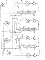
- Figur 2 mehrere Rohrreaktoren mit Rohrreaktorstrahldüse in Hintereinanderschaltung.
- In Figur 1 weist der Rohrreaktor 1 an seinem oberen Ende den Impulsraum 2 und an seinem unteren Ende die Produktabführungszone 3 auf. Zwischen diesen befinden sich die Rohre 4, deren Zwischenräume zum Impulsraum 2 und zur Produktabführungszone 3 hin mittels der Böden 5 und 6 als Kühlzone 12 verschlossen sind und zwecks Zu- und Abfuhr von Kühlmedium an die Leitungen 7 und 8 angeschlossen sind.
- Auf dem Rohrreaktor 1 ist in den Impulsraum 2 mündend die Rohrreaktorstrahldüse 9 angeordnet. Diese wird über die Leitungen 10 und 10 a mit der von einer nicht gezeigten Pumpe geförderten und in einem ebenfalls nicht gezeigten Wärmeaustauscher auf die erforderliche Temperatur eingestellten Flüssigphase als zentralem Treibstrahl und über die Leitungen 10 und 10 b als ringförmigem Nebenstrahl sowie über die Leitung 11 in einen zwischen dem Treibstrahl und dem Nebenstrahl gebildeten nicht gezeigten Ringraum mit der beispielsweise ebenfalls über eine Pumpe geförderten und in einem nicht gezeigten Wärmeaustauscher optimal temperierten Gasphase beschickt. Nach Durchströmen der Rohrreaktorstrahldüse 9 werden Flüssig- und Gasphase im Impulsraum 2 innig vermischt und gelangen unmittelbar in die Kühlzone 12. Das Oxydationsprodukt wird von der Pumpe 13 über den Wärmetauscher 14 und die Rohrleitung 15 weitergeleitet.
- Das im wesentlichen aus inerten Bestandteilen bestehende Restgas wird über die Leitung 16 zum Brüden-Kondensator 17 geleitet, wo das während der Reaktion sich gebildete Reaktionswasser abgeschieden wird, und gelangt nach Entspannung in eine nicht gezeigte Abluftreinigung. Zur Steuerung des Druckes im System ist in der Abluftleitung 18 die Regelung 19 vorgesehen.
- Der Oxydationsvorgang kann in weiten Bereichen gesteuert werden. Dazu werden in den Rohrleitungen entsprechende Steuer- und Regelventile vorgesehen. Durch die Verbindung der Produktabfuhrleitung 15 mit der Leitung 10 mittels der Leitung 20 und Anordnung eines Steuer- bzw. Regelventils an der Verbindungsstelle 21 kann bezweckt und erreicht werden, daß ein mehr oder weniger großer Teil des Oxydationsproduktes für einen beliebig festlegbaren Zeitraum im Oxydationskreislauf gehalten wird. Ebenso kann durch die Verbindungsleitung 22 zwischen Impulsraum 2 und Leitung 11 mit nicht gezeigtem Steuer- bzw. Regelventil bezweckt und erreicht werden, daß ein mehr oder weniger großer Teil der Gasphase mehr oder weniger lange im Oxydationskreislauf gehalten wird.
- Da im Rohrreaktor 1 keinerlei Toträume vorhanden sind und eine einstellbare hohe Strömungsgeschwindigkeit herrscht, wird die Reaktionswärme sowohl in der Kühlzone 12 als auch durch den außenliegenden Wärmetauscher 14 schnell und wirksam abgeführt. Dabei erweist es sich im Sinne einer optimalen Kühlwirkung als besonders vorteilhaft, die Steuerung bzw. Regelung des Prozeßablaufs so zu treffen, daß sich der Flüssigkeitsspiegel im Rohrreaktor möglichst genau in Höhe des oberen Endes der Rohre 4 bzw. des oberen Bodens 5 befindet.
- Das im Vorstehenden beschriebene Verfahren zur Oxydation in nur einem Rohrreaktor läßt sich durch die Kombination mehrerer solcher Rohrreaktoren wesentlich verbessern. So läßt sich durch mehrere Reaktionsstufen der Prozeß bezüglich Konzentration der Reaktionspartner, Mengenverhältnisse, Temperaturverhältnisse sowie Abführen der Reaktionswärme optimal gestalten, wodurch die Reaktion in allen wesentlichen Parametern beherrschbar wird und damit Ausbeute und Selektivität gegenüber den bekannten Verfahren wesentlich verbessert wird.
- Bei der in Figur 2 gezeigten Anwendung mehrerer Oxydatoren im mehrstufigen Prozeß sind gleiche Teile wieder mit den gleichen Bezugszeichen versehen.
- Die von der Pumpe 23 über den Wärmetauscher 24 durch die Leitungen 10, 10', 10" und die von den Pumpen 13, 13', 13" über die Leitung 20, 20', 20" geförderte Kreislaufmenge an Oxydationsprodukt können durch nicht gezeigte Steuer-und Regelorgane in beliebigen Verhältnissen variiert werden, so daß in jeder Stufe sowohl reines Ausgangsprodukt wie auch jede beliebige Mischung von Ausgangsprodukt und Oxydationsprodukt oxydiert werden kann. Vorteilhaft kann die Anordnung und Ausbildung so getroffen werden, daß die verschiedenen Stufen in beliebiger Kombination miteinander betrieben werden können, d.h. daß einzelne Stufen auch ausgeschaltet werden können.
- Die Möglichkeit der beliebigen Variation ist auch bezüglich der Menge und Zusammensetzung des Reaktionsgases gegeben, dessen Temperierung im Wärmeaustauscher 25 erfolgt. Beispielsweise kann der Reaktor 1 mit Ausgangsprodukt beschickt und über die Reaktoren 1', 1'' usw. zum Zielprodukt oxydiert werden. Das Oxydationsgas kann dabei im Gegenstrom geführt werden, d.h. die größte 0--Konzentration wird in der letzten Stufe angeboten und zur ersten Stufe hin abgebaut oder aber je nach 02-Gehalt nach jeder Stufe direkt in die Reinigungsanlage geleitet. Durch separate Frischgasbeimengung kann jede Stufe in ihrem 'Oxydationsablauf eingestellt werden, wobei die einzelnen Stufen durch Mischen von Frischprodukt und Umlaufprodukt auf günstigste Konzentration regulierbar sind.
- Bei dem für die Oxydation verwendeten sauerstoffhaltigen Gas kann es sich sowohl um ein mehr oder weniger große inerte Anteile aufweisendes Gas als auch um reinen Sauerstoff handeln, wobei die Steuerung bzw. Regelung des Ablaufs des Oxydations-Prozesses ohne Schwierigkeit in der jeweils erforderlichen Weise angepaßt werden kann. Bei entsprechender Prozeßführung hat die Verwendung reinen Sauerstoffes als Reaktionsgas den Vorteil, daß sich die Abgasmenge zumindest wesentlich verringern, u.U. sogar ganz vermeiden läßt.
- Die Reaktionswärme wird unmittelbar am Ort ihrer Entstehung, nämlich in den Kühlzonen 12, 12', 12" sowie in den außenliegenden Wärmeaustauschern 14, 14', 14'' usw. abgeführt. Kühlzonen und Wärmeaustauscher werden selbstverständlich einzeln regulierbar ausgebildet. Da sie vom Produkt gleichsam nach Art einer Kolbenströmung durchflossen werden, werden örtliche Überhitzungen vermieden.
- Die Abluft des letzten Reaktors kann, nachdem das Reaktionswasser auskondensiert ist, der vorhergehenden Stufe als Reaktionsgas dienen. Die 02-Konzentration kann dazu erforderlichenfalls mit Frischgas angehoben werden, das Abgas dieser vorhergehenden Stufe kann in gleicher Weise wiederum nach Auskondensieren des Reaktionswassers der ihr vorhergehenden Stufe zugeführt werden usw., wobei in jeder vorhergehenden Stufe der 02 Gehalt mit Frischgas eingestellt werden kann, bis schließlich das Abgas der ersten Stufe nach Auskondensieren des Reaktionswassers in die Reinigungsanlage geführt wird.
- Wie bei den bisher gebräuchlichen Oxydatoren kann auch bei dem hier beschriebenen Verfahren die Bildung explosiver Gemische in der Gasphase nicht unbedingt ausgeschlossen werden. Das Volumen des Gasraumes beträgt hier jedoch nur einen Bruchteil des Gasvolumens der bisher eingesetzten Apparaturen, wodurch die Gefahr schon erheblich gemindert ist. Um einen vollständigen Explosionsschutz zu gewährleisten, ist erfindungsgemäß vorgesehen, im Impulsraum eines jeden Rohrreaktors einen Ionisator in Form einer radioaktiven Quelle, insbesondere eines α-Strahlers anzuordnen.
Claims (2)
Priority Applications (1)
| Application Number | Priority Date | Filing Date | Title |
|---|---|---|---|
| AT85100791T ATE66911T1 (de) | 1984-01-27 | 1985-01-26 | Verfahren zur oxydation von fluessigen organischen stoffen. |
Applications Claiming Priority (2)
| Application Number | Priority Date | Filing Date | Title |
|---|---|---|---|
| DE3402807 | 1984-01-27 | ||
| DE3402807A DE3402807C2 (de) | 1984-01-27 | 1984-01-27 | Verfahren zur Oxydation von flüssigen organischen Stoffen |
Publications (3)
| Publication Number | Publication Date |
|---|---|
| EP0150835A2 true EP0150835A2 (de) | 1985-08-07 |
| EP0150835A3 EP0150835A3 (en) | 1987-04-08 |
| EP0150835B1 EP0150835B1 (de) | 1991-09-04 |
Family
ID=6226071
Family Applications (1)
| Application Number | Title | Priority Date | Filing Date |
|---|---|---|---|
| EP85100791A Expired - Lifetime EP0150835B1 (de) | 1984-01-27 | 1985-01-26 | Verfahren zur Oxydation von flüssigen organischen Stoffen |
Country Status (3)
| Country | Link |
|---|---|
| EP (1) | EP0150835B1 (de) |
| AT (1) | ATE66911T1 (de) |
| DE (2) | DE3402807C2 (de) |
Cited By (3)
| Publication number | Priority date | Publication date | Assignee | Title |
|---|---|---|---|---|
| GR1002882B (el) * | 1997-01-23 | 1998-03-24 | . | Μεθοδος και διαταξη επιβαλλομενης παλλομενης ροης σε στηλες με πληρωτικο υλικο |
| FR2818922A1 (fr) * | 2000-12-28 | 2002-07-05 | Atofina | Procede et dispositif pour la mise en oeuvre d'une reaction en milieu liquide avec degagement gazeux |
| CN119971918A (zh) * | 2025-02-14 | 2025-05-13 | 天津大学 | 用于乙苯液相过氧化的环路反应器系统及方法 |
Families Citing this family (2)
| Publication number | Priority date | Publication date | Assignee | Title |
|---|---|---|---|---|
| DE19543503C2 (de) * | 1995-11-22 | 2000-01-05 | Nukem Gmbh | Verfahren und Vorrichtung zum Bestrahlen von Flüssigkeiten mit energiereicher Strahlung sowie Verwendung der Vorrichtung |
| DE102008000785A1 (de) * | 2008-03-20 | 2009-09-24 | Evonik Röhm Gmbh | Verfahren zur Herstellung von Methacrylsäure |
Family Cites Families (6)
| Publication number | Priority date | Publication date | Assignee | Title |
|---|---|---|---|---|
| DE1767047U (de) * | 1958-03-18 | 1958-05-22 | Imhausen Werke G M B H | Oxydations-apparat mit innerem kuehlsystem fuer die luftoxydation von alkylsubstituierten aromatischen kohlenwasserstoffen zur abfuehrung der reaktionswaerme. |
| GB1013888A (en) * | 1963-03-12 | 1965-12-22 | Power Gas Ltd | Improvements in or relating to methods of and apparatus for reacting of fluids |
| US3534090A (en) * | 1966-11-04 | 1970-10-13 | Mobil Oil Corp | Hydrocarbon oxidation |
| US3590058A (en) * | 1968-06-07 | 1971-06-29 | Elmer J Lemaster | Atomized hydrocarbon oxygenation reaction process and apparatus therefor |
| DE2805915C3 (de) * | 1978-02-13 | 1981-11-05 | Dynamit Nobel Ag, 5210 Troisdorf | Reaktor zur Oxidation von Gemischen aus p-Xylol und p-Toluylsäuremethylester mit sauerstoffhaltigen Gasen in flüssiger Phase |
| DE3206661A1 (de) * | 1982-02-25 | 1983-09-01 | Basf Ag, 6700 Ludwigshafen | Verfahren zur vermeidung einer explosiblen gasphase bei gas/fluessig-reaktionen |
-
1984
- 1984-01-27 DE DE3402807A patent/DE3402807C2/de not_active Expired
-
1985
- 1985-01-26 AT AT85100791T patent/ATE66911T1/de not_active IP Right Cessation
- 1985-01-26 EP EP85100791A patent/EP0150835B1/de not_active Expired - Lifetime
- 1985-01-26 DE DE8585100791T patent/DE3583948D1/de not_active Expired - Lifetime
Cited By (6)
| Publication number | Priority date | Publication date | Assignee | Title |
|---|---|---|---|---|
| GR1002882B (el) * | 1997-01-23 | 1998-03-24 | . | Μεθοδος και διαταξη επιβαλλομενης παλλομενης ροης σε στηλες με πληρωτικο υλικο |
| FR2818922A1 (fr) * | 2000-12-28 | 2002-07-05 | Atofina | Procede et dispositif pour la mise en oeuvre d'une reaction en milieu liquide avec degagement gazeux |
| WO2002053277A1 (fr) * | 2000-12-28 | 2002-07-11 | Atofina | Procede et dispositif pour la mise en oeuvre d'une reaction en milieu liquide avec degagement gazeux |
| US7144568B2 (en) | 2000-12-28 | 2006-12-05 | Arkema France | Method and device for carrying out a reaction in liquid medium with gas evolution |
| EP2283921A1 (de) * | 2000-12-28 | 2011-02-16 | Arkema France | Vorrichtung zur Durchführung einer Reaktion in einem flüssigen Milieu mit Gasfreisetzung |
| CN119971918A (zh) * | 2025-02-14 | 2025-05-13 | 天津大学 | 用于乙苯液相过氧化的环路反应器系统及方法 |
Also Published As
| Publication number | Publication date |
|---|---|
| EP0150835B1 (de) | 1991-09-04 |
| DE3402807C2 (de) | 1986-12-18 |
| ATE66911T1 (de) | 1991-09-15 |
| EP0150835A3 (en) | 1987-04-08 |
| DE3583948D1 (de) | 1991-10-10 |
| DE3402807A1 (de) | 1985-08-08 |
Similar Documents
| Publication | Publication Date | Title |
|---|---|---|
| EP0156199B1 (de) | Verfahren zur Herstellung von Nitrobenzol | |
| DE2805915A1 (de) | Reaktor zur oxidation von alkylaromaten mit sauerstoffhaltigen gasen in fluessiger phase | |
| DE2711897C3 (de) | Verfahren und Vorrichtung zur katalytischen Oxidation von gasförmigen Schwefelverbindungen zu Schwefeltrioxid | |
| EP1387720A1 (de) | Reaktor für gas/flüssig- oder gas/flüssig/fest-reaktionen | |
| DE1619741A1 (de) | Mehrstufiger Verdampfer | |
| DE2363332B2 (de) | Verfahren und Vorrichtung zum Konzentrieren von verdünnten Lösungen korrosiver Stoffe | |
| EP0150835A2 (de) | Verfahren zur Oxydation von flüssigen organischen Stoffen | |
| DE2311085A1 (de) | Trennung von fluessigen aggressiven stoffgemischen | |
| DE3590168C2 (de) | ||
| DE2713863C2 (de) | ||
| DE1767033C3 (de) | ||
| DE1193493B (de) | Verfahren und Vorrichtung zur katalytischen Dampfphasen-Oxydation von aromatischen Kohlenwasserstoffen | |
| DE2058032A1 (de) | Verfahren und Vorrichtung zur kontinuierlichen Herstellung von Isocyanaten | |
| EP3338883B1 (de) | Vorrichtung und verfahren zum eintragen von gas in eine mehrzahl von prozessfluiden | |
| WO2020212334A1 (de) | Verfahren und vorrichtung zur herstellung von nitrobenzol | |
| DE2611454C3 (de) | Abtreibkolonne | |
| DE113932C (de) | ||
| EP0132224A1 (de) | Blasensäulen-Reaktor für Gas-Flüssig-Stoffaustauschreaktionen | |
| DE1288081B (de) | Verfahren und Sättiger zur Herstellung von Ammoniumnitrat | |
| DE838598C (de) | Verfahren und Vorrichtung zur Durchfuehrung exothermer katalytischer Reaktionen in Kontaktoefen | |
| DE1567751A1 (de) | Verfahren und Anlage zur Herstellung von hochkonzentrierter Salpetersaeure | |
| AT262323B (de) | Verfahren und Vorrichtung zur kontinuierlichen Umesterung von Alkylestern der Dicarbonsäuren mit Glykolen zu Diglykolestern | |
| EP0022473A1 (de) | Verfahren und Vorrichtung zum Regenerieren von Schwefelsäure | |
| DE1217934B (de) | Verfahren und Vorrichtung zur Intensivierung der Ammoniakbildung bei der katalytischen Ammoniaksynthese | |
| EP2144680A1 (de) | Kolonne mit querstromböden und flüssigkeitsverteiler |
Legal Events
| Date | Code | Title | Description |
|---|---|---|---|
| PUAI | Public reference made under article 153(3) epc to a published international application that has entered the european phase |
Free format text: ORIGINAL CODE: 0009012 |
|
| AK | Designated contracting states |
Kind code of ref document: A2 Designated state(s): AT BE CH DE FR GB IT LI NL SE Designated state(s): AT BE CH DE FR GB IT LI NL SE |
|
| PUAL | Search report despatched |
Free format text: ORIGINAL CODE: 0009013 |
|
| AK | Designated contracting states |
Kind code of ref document: A3 Designated state(s): AT BE CH DE FR GB IT LI NL SE |
|
| 17P | Request for examination filed |
Effective date: 19871005 |
|
| 17Q | First examination report despatched |
Effective date: 19881005 |
|
| RAP3 | Party data changed (applicant data changed or rights of an application transferred) |
Owner name: NEFF, ULRICH Owner name: BONSELS, PAUL, DIPL.-ING. |
|
| GRAA | (expected) grant |
Free format text: ORIGINAL CODE: 0009210 |
|
| AK | Designated contracting states |
Kind code of ref document: B1 Designated state(s): AT BE CH DE FR GB IT LI NL SE |
|
| PG25 | Lapsed in a contracting state [announced via postgrant information from national office to epo] |
Ref country code: SE Effective date: 19910904 |
|
| REF | Corresponds to: |
Ref document number: 66911 Country of ref document: AT Date of ref document: 19910915 Kind code of ref document: T |
|
| REF | Corresponds to: |
Ref document number: 3583948 Country of ref document: DE Date of ref document: 19911010 |
|
| ITF | It: translation for a ep patent filed | ||
| GBT | Gb: translation of ep patent filed (gb section 77(6)(a)/1977) | ||
| ET | Fr: translation filed | ||
| PGFP | Annual fee paid to national office [announced via postgrant information from national office to epo] |
Ref country code: GB Payment date: 19920117 Year of fee payment: 8 |
|
| PGFP | Annual fee paid to national office [announced via postgrant information from national office to epo] |
Ref country code: BE Payment date: 19920122 Year of fee payment: 8 |
|
| PG25 | Lapsed in a contracting state [announced via postgrant information from national office to epo] |
Ref country code: AT Effective date: 19920126 |
|
| PGFP | Annual fee paid to national office [announced via postgrant information from national office to epo] |
Ref country code: CH Payment date: 19920127 Year of fee payment: 8 |
|
| PGFP | Annual fee paid to national office [announced via postgrant information from national office to epo] |
Ref country code: NL Payment date: 19920131 Year of fee payment: 8 Ref country code: FR Payment date: 19920131 Year of fee payment: 8 |
|
| PLBE | No opposition filed within time limit |
Free format text: ORIGINAL CODE: 0009261 |
|
| STAA | Information on the status of an ep patent application or granted ep patent |
Free format text: STATUS: NO OPPOSITION FILED WITHIN TIME LIMIT |
|
| 26N | No opposition filed | ||
| PGFP | Annual fee paid to national office [announced via postgrant information from national office to epo] |
Ref country code: DE Payment date: 19920909 Year of fee payment: 8 |
|
| PG25 | Lapsed in a contracting state [announced via postgrant information from national office to epo] |
Ref country code: GB Effective date: 19930126 |
|
| PG25 | Lapsed in a contracting state [announced via postgrant information from national office to epo] |
Ref country code: LI Effective date: 19930131 Ref country code: CH Effective date: 19930131 Ref country code: BE Effective date: 19930131 |
|
| BERE | Be: lapsed |
Owner name: NEFF ULRICH Effective date: 19930131 Owner name: BONSELS PAUL Effective date: 19930131 |
|
| PG25 | Lapsed in a contracting state [announced via postgrant information from national office to epo] |
Ref country code: NL Effective date: 19930801 |
|
| NLV4 | Nl: lapsed or anulled due to non-payment of the annual fee | ||
| GBPC | Gb: european patent ceased through non-payment of renewal fee |
Effective date: 19930126 |
|
| PG25 | Lapsed in a contracting state [announced via postgrant information from national office to epo] |
Ref country code: FR Effective date: 19930930 |
|
| REG | Reference to a national code |
Ref country code: CH Ref legal event code: PL |
|
| PG25 | Lapsed in a contracting state [announced via postgrant information from national office to epo] |
Ref country code: DE Effective date: 19931001 |
|
| REG | Reference to a national code |
Ref country code: FR Ref legal event code: ST |