EP0146442B1 - Beschickungsvorrichtung für einen Horizontal-Durchlaufofen zum Erwärmen von Glasscheiben - Google Patents
Beschickungsvorrichtung für einen Horizontal-Durchlaufofen zum Erwärmen von Glasscheiben Download PDFInfo
- Publication number
- EP0146442B1 EP0146442B1 EP84402311A EP84402311A EP0146442B1 EP 0146442 B1 EP0146442 B1 EP 0146442B1 EP 84402311 A EP84402311 A EP 84402311A EP 84402311 A EP84402311 A EP 84402311A EP 0146442 B1 EP0146442 B1 EP 0146442B1
- Authority
- EP
- European Patent Office
- Prior art keywords
- bars
- loading
- glass sheets
- transport
- glass
- Prior art date
- Legal status (The legal status is an assumption and is not a legal conclusion. Google has not performed a legal analysis and makes no representation as to the accuracy of the status listed.)
- Expired
Links
- 239000011521 glass Substances 0.000 title claims description 48
- 238000010438 heat treatment Methods 0.000 claims description 3
- 238000005496 tempering Methods 0.000 claims description 3
- 238000005452 bending Methods 0.000 description 3
- 238000013459 approach Methods 0.000 description 1
- 239000005357 flat glass Substances 0.000 description 1
- 238000009434 installation Methods 0.000 description 1
Images
Classifications
-
- B—PERFORMING OPERATIONS; TRANSPORTING
- B65—CONVEYING; PACKING; STORING; HANDLING THIN OR FILAMENTARY MATERIAL
- B65G—TRANSPORT OR STORAGE DEVICES, e.g. CONVEYORS FOR LOADING OR TIPPING, SHOP CONVEYOR SYSTEMS OR PNEUMATIC TUBE CONVEYORS
- B65G49/00—Conveying systems characterised by their application for specified purposes not otherwise provided for
- B65G49/05—Conveying systems characterised by their application for specified purposes not otherwise provided for for fragile or damageable materials or articles
- B65G49/06—Conveying systems characterised by their application for specified purposes not otherwise provided for for fragile or damageable materials or articles for fragile sheets, e.g. glass
- B65G49/063—Transporting devices for sheet glass
- B65G49/064—Transporting devices for sheet glass in a horizontal position
-
- C—CHEMISTRY; METALLURGY
- C03—GLASS; MINERAL OR SLAG WOOL
- C03B—MANUFACTURE, SHAPING, OR SUPPLEMENTARY PROCESSES
- C03B35/00—Transporting of glass products during their manufacture, e.g. hot glass lenses, prisms
- C03B35/14—Transporting hot glass sheets or ribbons, e.g. by heat-resistant conveyor belts or bands
- C03B35/16—Transporting hot glass sheets or ribbons, e.g. by heat-resistant conveyor belts or bands by roller conveyors
-
- C—CHEMISTRY; METALLURGY
- C03—GLASS; MINERAL OR SLAG WOOL
- C03B—MANUFACTURE, SHAPING, OR SUPPLEMENTARY PROCESSES
- C03B2225/00—Transporting hot glass sheets during their manufacture
- C03B2225/02—Means for positioning, aligning or orientating the sheets during their travel, e.g. stops
Definitions
- the invention relates to a device for loading a horizontal continuous oven for heating glass sheets to the tempering or bending temperature, consisting of a roller conveyor, placed in series with the transport system. continuous oven, with at least one loading station in which the glass sheets are positioned and loaded on support bars, arranged between the transport roller and capable, at a given time. lower simultaneously under the support bed formed by the transport rollers, to allow the transfer of the glass sheets on the roller conveyor.
- the bars which can be lowered are arranged on a common frame.
- the frame is lowered with the bars using a lifting device and the glass sheet (s) pass over the loading rollers with which she or they are transported to the oven.
- the frame with the bars is lifted by the lifting device and the next sheet or sheets of glass can be loaded and positioned.
- a lowering of the bars at a precise moment is important for current automated continuous ovens, in order to ensure on the one hand a given final temperature of the glass sheet, within the limits of tolerances, and on the other hand so that the glass sheet indeed occupies a predetermined position in the processing station following the furnace, for example in the bending station.
- the rate of movement of the glass sheets can be very high in continuous ovens with high throughput, so that the loading and alignment of the glass sheets on the support bars must be carried out in too short a time for careful alignment glass sheets.
- the invention aims to develop a loading device where, without reducing the rate of travel in the oven, it extends the time of laying and alignment of the glass sheets.
- this object is obtained by the fact that at least one of the bars of the loading station is mounted independently of the others and provided with its own lifting device, and is lifted before the other bars as soon as the area of the conveyor lying above it is released from the glass sheet which passes over the transport rollers.
- the bars can receive a new glass sheet only when the glass sheet, transferred to the roller conveyor, has also left the area of the conveyor located above the last bar, according to the invention, one or more of the rear bars, seen in the direction of transport, are lifted before the last bars.
- the loading surface formed by the bars is available with a lead time for loading the next sheet of glass.
- a loading station comprises two bars raised and lowered independently of one another. This configuration has the advantage that the next glass sheet can be already supported, at least partially by the first raised bar. If in addition, this first bar is raised by a sufficient height, a sheet of glass, which would have been loaded on a second loading station, can engage, if necessary, between the transport bed and the bar then even that the first loading station is not completely free.
- each bar is mounted independently of its neighbor and provided with its own lifting device. In addition, it is controlled by a clean detector, attached to each bar and located at the rear of each, seen in the direction of transport.
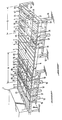
- the single board represents a loading device according to the invention having two loading stations located one behind the other.
- the device for loading a continuous furnace 1 for heating glass sheets 2, 3, 4, 5 to their tempering or bending temperature comprises a roller conveyor 6, formed from a series of transport rollers 7 controlled cylinders which are placed on the longitudinal beams 8, 9.
- the transport rollers 7 belonging to the loading device have the same speed of rotation as those of the transport device of the continuous oven.
- the side members are on supports 10.
- each bar 12, 13, 14 and 15 there is respectively a detector device formed by a photoelectric cell 22, 23, 24 and 25.
- These photoelectric cells control the jacks 16 to 19, belonging respectively to the bars 12 to 15 so that, as soon as the rear edge of a sheet of glass running on the conveyor 6 passes the photoelectric cell, the latter sends a signal which controls the lifting of the corresponding bar.
- Charging station B is constructed in the same way. It also includes four bars 32, 33, 34 and 35, in the form of gantries, placed at their ends on jacks 36, 37, 38 and 39 which lower and raise them. Associated with each bar, there is a detector device, formed by a photoelectric cell 42, 43, 44 and 45 arranged at the rear of the bar, seen in the direction of transport.
- adjusting elements 46 are further arranged on the support arms 47, themselves connected, directly or by girder-shaped longitudinal members 48, to the frame of the roller conveyor.
- the adjusting elements 46 have an adjustable position according to the shape and size of the glass sheets. In general, three adjustment elements 46 are sufficient to fix exactly the desired position of the glass sheet.
- All the conveyor rollers 7 are in continuous rotation, they take care of the glass sheets as soon as the bars lower. While the bars 12 and 13 are lowered, the glass sheet 2 is located on the transport rollers 7, roughly in the region of the conveyor located above these lowered bars 12, 13. Previously, the sheet glass had been placed on the bars 14,15, positioned thanks to the three adjustment elements 46 and transferred to the loading rollers by the common lowering of the four bars 12, 13, 14 and 15. After the rear edge of the sheet of glass 2 has passed the photocell 25, the lifting device 19, then started, has raised the bar 15. Similarly, the bar 14 has been raised at the moment when the rear edge of the sheet of glass 2 passed the photocell 24. Once the two bars 14 and 15 were raised, a sheet of glass 3 was immediately loaded thereon and positioned using the three corresponding adjustment elements.
- the glass sheet 4 circulates under the raised bars 14, 15. This glass sheet 4, like the glass sheet 5, will have been previously loaded on the bars 32, 33, 34 35 in the loading station B.
- the next glass sheet 5 is loaded on the transport rollers 7 by simultaneously lowering the bars 32 to 35.
- the commands for the simultaneous lowering of the four bars of a loading station can be given, in a known manner by a central control unit of the continuous oven.
Landscapes
- Chemical & Material Sciences (AREA)
- Engineering & Computer Science (AREA)
- Materials Engineering (AREA)
- Organic Chemistry (AREA)
- Re-Forming, After-Treatment, Cutting And Transporting Of Glass Products (AREA)
- Tunnel Furnaces (AREA)
- Intermediate Stations On Conveyors (AREA)
- Sheets, Magazines, And Separation Thereof (AREA)
Claims (8)
Applications Claiming Priority (2)
| Application Number | Priority Date | Filing Date | Title |
|---|---|---|---|
| DE3341207A DE3341207C1 (de) | 1983-11-14 | 1983-11-14 | Beschickungsvorrichtung fuer einen Horizontal-Durchlaufofen zum Erwaermen von Glasscheiben |
| DE3341207 | 1983-11-14 |
Publications (2)
| Publication Number | Publication Date |
|---|---|
| EP0146442A1 EP0146442A1 (de) | 1985-06-26 |
| EP0146442B1 true EP0146442B1 (de) | 1987-09-09 |
Family
ID=6214318
Family Applications (1)
| Application Number | Title | Priority Date | Filing Date |
|---|---|---|---|
| EP84402311A Expired EP0146442B1 (de) | 1983-11-14 | 1984-11-14 | Beschickungsvorrichtung für einen Horizontal-Durchlaufofen zum Erwärmen von Glasscheiben |
Country Status (4)
| Country | Link |
|---|---|
| US (1) | US4634329A (de) |
| EP (1) | EP0146442B1 (de) |
| JP (2) | JPS60169080A (de) |
| DE (2) | DE3341207C1 (de) |
Cited By (1)
| Publication number | Priority date | Publication date | Assignee | Title |
|---|---|---|---|---|
| CN104386908A (zh) * | 2014-11-19 | 2015-03-04 | 南京熊猫电子股份有限公司 | 一种玻璃的±90°旋转传输装置 |
Families Citing this family (18)
| Publication number | Priority date | Publication date | Assignee | Title |
|---|---|---|---|---|
| DE3341207C1 (de) * | 1983-11-14 | 1984-10-04 | VEGLA Vereinigte Glaswerke GmbH, 5100 Aachen | Beschickungsvorrichtung fuer einen Horizontal-Durchlaufofen zum Erwaermen von Glasscheiben |
| US4632688A (en) * | 1985-11-08 | 1986-12-30 | Libbey-Owens-Ford Company | Apparatus and method for treating glass sheets |
| GB2193709B (en) * | 1986-07-28 | 1989-12-13 | Libbey Owens Ford Co | Apparatus for aligning glass sheets in a production line |
| FR2606383B1 (fr) * | 1986-11-06 | 1989-01-13 | Saint Gobain Vitrage | Positionnement de plaques de verre en vue notamment de leur bombage |
| FR2644778B1 (fr) * | 1989-03-24 | 1991-05-31 | Saint Gobain Vitrage | Positionnement d'une feuille de verre defilant sur un convoyeur |
| US5086907A (en) * | 1990-10-17 | 1992-02-11 | Glasstech, Inc. | Glass sheet transferring device |
| JP3005788B2 (ja) * | 1993-11-08 | 2000-02-07 | 株式会社新川 | リードフレームのベーク炉 |
| FI100526B2 (fi) * | 1996-05-22 | 2002-09-20 | Uniglass Engineering Oy | Menetelmä ja laitteisto teloilla varustetun karkaisu-uunin karkaisuprosessin ohjaamiseksi |
| US6209709B1 (en) * | 1998-12-24 | 2001-04-03 | Ouellette Machinery Systems, Inc. | Dunnage infeed station |
| CN1317211C (zh) * | 2005-02-25 | 2007-05-23 | 友达光电股份有限公司 | 输送设备 |
| JP4737750B2 (ja) * | 2005-08-19 | 2011-08-03 | 本田技研工業株式会社 | チェーンガイド装置 |
| KR100747963B1 (ko) | 2006-03-22 | 2007-08-08 | 백정욱 | 콘베어시스템으로 가공하는 다층유리판의 접합장치 |
| US8826693B2 (en) | 2010-08-30 | 2014-09-09 | Corning Incorporated | Apparatus and method for heat treating a glass substrate |
| CN104534869B (zh) * | 2014-12-19 | 2017-05-03 | 广东摩德娜科技股份有限公司 | 一种用于烧成设备上的驮载结构 |
| CN110668183A (zh) * | 2019-10-09 | 2020-01-10 | 陕西神木瑞诚玻璃有限公司 | 一种玻璃生产线的辊道挡辊装置及其控制方法 |
| EP4118018B1 (de) * | 2020-03-20 | 2025-06-25 | Hubert Haselsteiner | Beladesystem |
| CN112427270A (zh) * | 2020-11-27 | 2021-03-02 | 重庆惠科金渝光电科技有限公司 | 一种加热装置及加热方法 |
| CN113682719B (zh) * | 2021-08-13 | 2023-08-11 | 宣城吉鼎玻机械有限公司 | 一种玻璃钢化炉的玻璃上片方法 |
Family Cites Families (14)
| Publication number | Priority date | Publication date | Assignee | Title |
|---|---|---|---|---|
| FR773808A (fr) * | 1933-10-02 | 1934-11-26 | Glaceries Sambre Sa | Appareil pour le transport des feuilles de verre |
| US3254778A (en) * | 1964-03-06 | 1966-06-07 | Marland Foundation | Drive mechanism for roller hearth furnace |
| US3251452A (en) * | 1964-06-03 | 1966-05-17 | Western Electric Co | Article spacing apparatus for conveyor systems |
| US3249415A (en) * | 1964-12-24 | 1966-05-03 | Permaglass | Apparatus for heat treating glass sheets |
| US3565236A (en) * | 1968-10-21 | 1971-02-23 | Us Plywood Champ Papers Inc | Feeder for veneer crowder |
| SE7400437L (sv) * | 1974-01-14 | 1975-07-15 | Gunnar Thure Eliassen | Transportanleggning |
| JPS5284679A (en) * | 1976-01-05 | 1977-07-14 | Yamato Scale Co Ltd | Regulating device of article transfer interval on belt conveyor |
| JPS5421849A (en) * | 1977-07-20 | 1979-02-19 | Kopia Kk | Waste paper receiving apparatus for copier |
| US4282026A (en) * | 1978-01-25 | 1981-08-04 | Mcmaster Harold | Apparatus for bending and tempering glass |
| FR2495128A1 (fr) * | 1980-12-01 | 1982-06-04 | Saint Gobain Vitrage | Procede et dispositif pour l'alimentation d'un four de chauffage de feuilles de verre |
| ZA822760B (en) * | 1981-05-01 | 1983-03-30 | John Stephen Nitschke | Control system for monitoring and controlling the processing of glass sheets in a glass processing environment |
| US4364766A (en) * | 1981-05-01 | 1982-12-21 | Nitschke John Stephen | Control system for monitoring and controlling the processing of glass sheets in a glass processing environment |
| JPS58112910A (ja) * | 1981-12-17 | 1983-07-05 | ケルベル・アクチエンゲゼルシヤフト | たばこ加工産業の棒状製品用の容器を充填しかつ搬送するための装置 |
| DE3341207C1 (de) * | 1983-11-14 | 1984-10-04 | VEGLA Vereinigte Glaswerke GmbH, 5100 Aachen | Beschickungsvorrichtung fuer einen Horizontal-Durchlaufofen zum Erwaermen von Glasscheiben |
-
1983
- 1983-11-14 DE DE3341207A patent/DE3341207C1/de not_active Expired
-
1984
- 1984-11-14 US US06/671,204 patent/US4634329A/en not_active Expired - Lifetime
- 1984-11-14 EP EP84402311A patent/EP0146442B1/de not_active Expired
- 1984-11-14 DE DE8484402311T patent/DE3465975D1/de not_active Expired
- 1984-11-14 JP JP59238678A patent/JPS60169080A/ja active Pending
-
1993
- 1993-04-27 JP JP1993021947U patent/JPH077287Y2/ja not_active Expired - Lifetime
Cited By (1)
| Publication number | Priority date | Publication date | Assignee | Title |
|---|---|---|---|---|
| CN104386908A (zh) * | 2014-11-19 | 2015-03-04 | 南京熊猫电子股份有限公司 | 一种玻璃的±90°旋转传输装置 |
Also Published As
| Publication number | Publication date |
|---|---|
| DE3465975D1 (en) | 1987-10-15 |
| JPS60169080A (ja) | 1985-09-02 |
| EP0146442A1 (de) | 1985-06-26 |
| JPH0594238U (ja) | 1993-12-24 |
| JPH077287Y2 (ja) | 1995-02-22 |
| US4634329A (en) | 1987-01-06 |
| DE3341207C1 (de) | 1984-10-04 |
Similar Documents
| Publication | Publication Date | Title |
|---|---|---|
| EP0146442A1 (de) | Beschickungsvorrichtung für einen Horizontal-Durchlaufofen zum Erwärmen von Glasscheiben | |
| EP0381256B1 (de) | Vorrichtung zum Überführen von Gegenständen, wie gefüllten Säcken, von einem Förderer zu einer Sammelvorrichtung, wie einem Karton, der unter diesem Förderer steht | |
| US4278377A (en) | Method of and apparatus for stacking channel bars | |
| FR2606301A1 (fr) | Machine de triage comportant des moyens formant convoyeur d'articles, pouvant etre positionnes d'avance en fonction de la destination de dechargement | |
| EP2331435B1 (de) | Verfahren und vorrichtung zum beladen eines behälters mit produkten aus grossflächig dünnen glasscheiben | |
| CA2210728A1 (en) | Conveyor belt lift apparatus | |
| FR2549464A1 (fr) | Installation a courbure facilement modifiable pour le bombage et la trempe de feuilles de verre | |
| US3272331A (en) | Wiener orienter | |
| EP0445695A2 (de) | Anlage zum Mehrschichtspeichern und Sortieren von Fliesen, insbesondere von sogenannten speziellen Keramikfliesen sowie kleinen glasierten Bodenfliesen, Mosaiksteinen und dergleichen | |
| GB1341286A (en) | Sheet handling apparatus | |
| FR2429735A1 (fr) | Dechargeur-empileur automatique pour la manoeuvre des poteaux et des lattes en bois ou autres comme les barres pour corniches | |
| EP0039627B1 (de) | Verfahren und Vorrichtung zum Aufrichten und Paketieren von Dachziegeln oder sonstiger Produkte | |
| FR2718001A1 (fr) | Dispositif de chargement et de déchargement en produit à cuire d'une structure de table de cuisson. | |
| US20030136639A1 (en) | Method and device for transporting and turning objects | |
| GB2225315A (en) | Apparatus for stacking and de-stacking elongate products | |
| FR2691957A1 (fr) | Table de marge de machines à imprimer. | |
| GB2040852A (en) | Apparatus for inverting loads | |
| US3847267A (en) | Pickup mechanism | |
| FR2470097A1 (fr) | Convoyeur avec systeme de nettoyage | |
| JP3391672B2 (ja) | 苗箱展開回収装置 | |
| SU865465A1 (ru) | Слитковоз обжимного прокатного стана | |
| FR2725955A1 (fr) | Systeme d'etiquetage automatique de produits | |
| JPH019794Y2 (de) | ||
| JPS5856694B2 (ja) | 板状物体送り出し装置 | |
| JPS5823780Y2 (ja) | 物品搬送仕分け機構 |
Legal Events
| Date | Code | Title | Description |
|---|---|---|---|
| PUAI | Public reference made under article 153(3) epc to a published international application that has entered the european phase |
Free format text: ORIGINAL CODE: 0009012 |
|
| AK | Designated contracting states |
Designated state(s): BE DE FR GB IT SE |
|
| 17P | Request for examination filed |
Effective date: 19850718 |
|
| 17Q | First examination report despatched |
Effective date: 19861125 |
|
| GRAA | (expected) grant |
Free format text: ORIGINAL CODE: 0009210 |
|
| AK | Designated contracting states |
Kind code of ref document: B1 Designated state(s): BE DE FR GB IT SE |
|
| ITF | It: translation for a ep patent filed | ||
| GBT | Gb: translation of ep patent filed (gb section 77(6)(a)/1977) | ||
| REF | Corresponds to: |
Ref document number: 3465975 Country of ref document: DE Date of ref document: 19871015 |
|
| PLBE | No opposition filed within time limit |
Free format text: ORIGINAL CODE: 0009261 |
|
| STAA | Information on the status of an ep patent application or granted ep patent |
Free format text: STATUS: NO OPPOSITION FILED WITHIN TIME LIMIT |
|
| 26N | No opposition filed | ||
| ITTA | It: last paid annual fee | ||
| EAL | Se: european patent in force in sweden |
Ref document number: 84402311.9 |
|
| PGFP | Annual fee paid to national office [announced via postgrant information from national office to epo] |
Ref country code: SE Payment date: 20001013 Year of fee payment: 17 |
|
| PGFP | Annual fee paid to national office [announced via postgrant information from national office to epo] |
Ref country code: GB Payment date: 20001018 Year of fee payment: 17 |
|
| PGFP | Annual fee paid to national office [announced via postgrant information from national office to epo] |
Ref country code: FR Payment date: 20001108 Year of fee payment: 17 |
|
| PGFP | Annual fee paid to national office [announced via postgrant information from national office to epo] |
Ref country code: DE Payment date: 20001205 Year of fee payment: 17 |
|
| PGFP | Annual fee paid to national office [announced via postgrant information from national office to epo] |
Ref country code: BE Payment date: 20001212 Year of fee payment: 17 |
|
| PG25 | Lapsed in a contracting state [announced via postgrant information from national office to epo] |
Ref country code: GB Free format text: LAPSE BECAUSE OF NON-PAYMENT OF DUE FEES Effective date: 20011114 |
|
| PG25 | Lapsed in a contracting state [announced via postgrant information from national office to epo] |
Ref country code: SE Free format text: LAPSE BECAUSE OF NON-PAYMENT OF DUE FEES Effective date: 20011115 |
|
| PG25 | Lapsed in a contracting state [announced via postgrant information from national office to epo] |
Ref country code: BE Free format text: LAPSE BECAUSE OF NON-PAYMENT OF DUE FEES Effective date: 20011130 |
|
| REG | Reference to a national code |
Ref country code: GB Ref legal event code: IF02 |
|
| BERE | Be: lapsed |
Owner name: SAINT-GOBAIN VITRAGE Effective date: 20011130 |
|
| EUG | Se: european patent has lapsed |
Ref document number: 84402311.9 |
|
| PG25 | Lapsed in a contracting state [announced via postgrant information from national office to epo] |
Ref country code: DE Free format text: LAPSE BECAUSE OF NON-PAYMENT OF DUE FEES Effective date: 20020702 |
|
| PG25 | Lapsed in a contracting state [announced via postgrant information from national office to epo] |
Ref country code: FR Free format text: LAPSE BECAUSE OF NON-PAYMENT OF DUE FEES Effective date: 20020730 |
|
| REG | Reference to a national code |
Ref country code: FR Ref legal event code: ST |
|
| REG | Reference to a national code |
Ref country code: FR Ref legal event code: ST |