EP0144076B1 - Dienstintegriertes, digitales Nachrichtenübertragungssystem - Google Patents
Dienstintegriertes, digitales Nachrichtenübertragungssystem Download PDFInfo
- Publication number
- EP0144076B1 EP0144076B1 EP84114458A EP84114458A EP0144076B1 EP 0144076 B1 EP0144076 B1 EP 0144076B1 EP 84114458 A EP84114458 A EP 84114458A EP 84114458 A EP84114458 A EP 84114458A EP 0144076 B1 EP0144076 B1 EP 0144076B1
- Authority
- EP
- European Patent Office
- Prior art keywords
- mux
- multiplexer
- input
- signal
- demultiplexer
- Prior art date
- Legal status (The legal status is an assumption and is not a legal conclusion. Google has not performed a legal analysis and makes no representation as to the accuracy of the status listed.)
- Expired - Lifetime
Links
- 230000005540 biological transmission Effects 0.000 title claims abstract description 15
- 238000002360 preparation method Methods 0.000 claims abstract description 6
- 230000008878 coupling Effects 0.000 claims abstract description 3
- 238000010168 coupling process Methods 0.000 claims abstract description 3
- 238000005859 coupling reaction Methods 0.000 claims abstract description 3
- 238000003780 insertion Methods 0.000 claims abstract 2
- 230000037431 insertion Effects 0.000 claims abstract 2
- 238000004519 manufacturing process Methods 0.000 description 2
- 239000011159 matrix material Substances 0.000 description 2
- 230000000712 assembly Effects 0.000 description 1
- 238000000429 assembly Methods 0.000 description 1
- 238000010276 construction Methods 0.000 description 1
- 239000013307 optical fiber Substances 0.000 description 1
- 238000005070 sampling Methods 0.000 description 1
Images

Classifications
-
- H—ELECTRICITY
- H04—ELECTRIC COMMUNICATION TECHNIQUE
- H04N—PICTORIAL COMMUNICATION, e.g. TELEVISION
- H04N21/00—Selective content distribution, e.g. interactive television or video on demand [VOD]
- H04N21/20—Servers specifically adapted for the distribution of content, e.g. VOD servers; Operations thereof
- H04N21/23—Processing of content or additional data; Elementary server operations; Server middleware
- H04N21/236—Assembling of a multiplex stream, e.g. transport stream, by combining a video stream with other content or additional data, e.g. inserting a URL [Uniform Resource Locator] into a video stream, multiplexing software data into a video stream; Remultiplexing of multiplex streams; Insertion of stuffing bits into the multiplex stream, e.g. to obtain a constant bit-rate; Assembling of a packetised elementary stream
- H04N21/2365—Multiplexing of several video streams
-
- H—ELECTRICITY
- H04—ELECTRIC COMMUNICATION TECHNIQUE
- H04J—MULTIPLEX COMMUNICATION
- H04J3/00—Time-division multiplex systems
- H04J3/16—Time-division multiplex systems in which the time allocation to individual channels within a transmission cycle is variable, e.g. to accommodate varying complexity of signals, to vary number of channels transmitted
- H04J3/1605—Fixed allocated frame structures
-
- H—ELECTRICITY
- H04—ELECTRIC COMMUNICATION TECHNIQUE
- H04N—PICTORIAL COMMUNICATION, e.g. TELEVISION
- H04N21/00—Selective content distribution, e.g. interactive television or video on demand [VOD]
- H04N21/40—Client devices specifically adapted for the reception of or interaction with content, e.g. set-top-box [STB]; Operations thereof
- H04N21/43—Processing of content or additional data, e.g. demultiplexing additional data from a digital video stream; Elementary client operations, e.g. monitoring of home network or synchronising decoder's clock; Client middleware
- H04N21/434—Disassembling of a multiplex stream, e.g. demultiplexing audio and video streams, extraction of additional data from a video stream; Remultiplexing of multiplex streams; Extraction or processing of SI; Disassembling of packetised elementary stream
- H04N21/4347—Demultiplexing of several video streams
-
- H—ELECTRICITY
- H04—ELECTRIC COMMUNICATION TECHNIQUE
- H04Q—SELECTING
- H04Q11/00—Selecting arrangements for multiplex systems
- H04Q11/04—Selecting arrangements for multiplex systems for time-division multiplexing
- H04Q11/0428—Integrated services digital network, i.e. systems for transmission of different types of digitised signals, e.g. speech, data, telecentral, television signals
- H04Q11/0478—Provisions for broadband connections
-
- H—ELECTRICITY
- H04—ELECTRIC COMMUNICATION TECHNIQUE
- H04J—MULTIPLEX COMMUNICATION
- H04J2203/00—Aspects of optical multiplex systems other than those covered by H04J14/05 and H04J14/07
- H04J2203/0001—Provisions for broadband connections in integrated services digital network using frames of the Optical Transport Network [OTN] or using synchronous transfer mode [STM], e.g. SONET, SDH
- H04J2203/0028—Local loop
-
- H—ELECTRICITY
- H04—ELECTRIC COMMUNICATION TECHNIQUE
- H04J—MULTIPLEX COMMUNICATION
- H04J2203/00—Aspects of optical multiplex systems other than those covered by H04J14/05 and H04J14/07
- H04J2203/0001—Provisions for broadband connections in integrated services digital network using frames of the Optical Transport Network [OTN] or using synchronous transfer mode [STM], e.g. SONET, SDH
- H04J2203/0089—Multiplexing, e.g. coding, scrambling, SONET
Definitions
- the invention relates to an integrated service, digital message transmission system according to the preamble of the claim.
- Such a system is described in Schoenentechnische Zeitschrift, vol. 35 (1982), issue 11, pp. 680 to 684.
- various broadband and narrowband services (television, video telephony, radio, telephony, data) are transmitted from a central office to many subscribers.
- telephony signals are transmitted as broadband services and various narrowband services.
- a separate broadband and separate additional channel multiplexer is required for each of the many subscribers for the direction of central subscribers and for the opposite direction, a separate return channel multiplexer.
- the object of the invention is to design the above message transmission system in a manner which allows inexpensive production of the additional channel and return channel multiplexers required in large numbers.
- the many subscriber-specific additional channel multiplexers can be constructed very simply, since in them only the Empty spaces must be occupied with the bits for the narrowband signals.
- the construction of the additional channel multiplexer from a demultiplexer and a multiplexer and their connection to one another means that this module can also be used as a return channel demultiplexer. This leads to a large number of identical assemblies being required, which makes the use of rational mass production processes worthwhile.
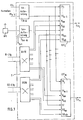
- FIG. 1 shows a center Z of the message transmission system.
- FIG. 2 shows one of the line sets LST present in the control center in detail.
- FIG. 1 is first described.
- the message transmission system consists of a central office Z and a large number of subscribers connected to it. Only the subscriber lines leading to the first (Tln l ) and the last subscriber (Tln m ) are drawn here. Each of these subscriber lines leads to a line set LST assigned to the respective subscriber within the control center. Only the first (LST,) and the last (LST m ) wiring harness are drawn here.
- the control center Since television programs are offered to the participants, the control center has several inputs FS, through FS n-1 , for television programs.
- the broadcasts of the broadcasting stations which are transmitted via cable or received by local antennas, as well as locally produced performances, are fed to a TV preparation module TV-A.
- the television programs are processed to an equal number of digital video signals TV, up to TV n-1 with a bit rate of 34.368 Mbit / s each, which are distributed to all line sets LST to LST.
- the central Z has a sound processing module A-A.
- An Ant 30 antenna system or 60 monophonic sound broadcasting programs feed this sound processing. There they are processed together with synchronizing signals Syn to form a digital sound multiplex signal ST, so that one line is sufficient to distribute them to the line sets LST to LST.
- This audio multiplex signal has the same bit rate as the digital video signals TV 1 to TV n-1 .
- An image telephone service is also available, for which purpose an image telephone switching matrix BIFE is provided in the central office. Via this switching matrix, each of the subscribers Tln 1 to Tln m can set up a video telephone connection to each other of these subscribers. Connections to subscribers from other centers are also possible via the B-Ltg telephony long-distance lines.
- the video telephone switching network BIFE is connected to the line sets LST via two subscriber-specific lines B an and B ab , one for each direction of transmission, digital video telephony signals having the same bit rate as those of the digital video signals TV to TV n-1 being transmitted via these lines .
- narrowband signals such as conventional telephony and data
- Such services are transmitted in a network for which the term “Integrated Services Digital Network”, abbreviated “ISDN”, has become established.
- ISDN Integrated Services Digital Network
- a narrowband switching network ISDN is provided in the control center, which is connected via two subscriber-specific lines SD in and SD out , one for each transmission direction, with the line sets LST to LST.
- the ISDN lines SD-Ltg are provided for connections with the subscribers of other centers.
- a line set LST is shown in detail in FIG.
- the lines already drawn in FIG. 1 are shown on the left edge.
- the lines for the video signals TV 1 to TV n-1 are connected to a broadband switching network BB-K.
- the line for the incoming video telephone signal B an is also connected as a video signal TV n to the broadband switching network BB-K.
- each of the z. B. 12 video signals TV 1 to TV n to one of the main broadband channels K1 to K3.
- An additional channel multiplexer Z-Mux is also provided, which combines the audio multiplex signal ST and the incoming narrowband signals SD to form a broadband additional channel K4.
- These four broadband main and additional channels reach a broadband multiplexer BB-Mux via a module for phase adjustment Ph as broadband main and additional channels K1 'to K4', where these channels are combined to form a broadband multiplex signal BBS.
- This broadband multiplex signal reaches the subscriber via an electrical-optical converter W1, via a duplexer Dp and via an optical fiber LLF.
- An optical-electrical converter W2 and a return channel demultiplexer R-Dem are provided for the transmission of a broadband return channel R in the opposite direction.
- This back channel demultiplexer provides at its outputs the image telephone return signal B, and the narrow-band return signal from SD.
- a sampling frequency of 32 kHz is customary in the digital transmission of sound broadcasting programs, each sample value being transmitted with 16 bits. This results in a bit rate of 512 kbit / s for a monophonic sound channel or 1024 kbit / s for a stereophonic sound channel. 30 stereophonic radio programs result in a bit rate of 30.72 Mbit / s. Nevertheless, a frame structure with the same bit rate as that of the digital video signals, namely with 34.368 Mbit / s, is provided for the sound multiplex signal.
- the additional channel multiplexer Z-Mux and the return channel demultiplexer R-Dem have the same structure and each consist of a multiplexer Mux and a demultiplexer Demux.
- Each multiplexer Mux has an output A M and a first input E, and a second input E2.
- Each demultiplexer Demux has a first outlet A, and a second output A 2 and an input E D.
- the first output A of each demultiplexer Demux is connected to the first input E of the associated multiplexer Mux.
- Each demultiplexer Demux outputs the digital signal applied to its input E D unchanged at its first output A ,. Only the bits of the signal to be branched appear at its second output A 2 .
- Each multiplexer Mux outputs the digital signal applied to its first input E 1 at the same bit rate at its output A M , the bits assigned to the signals applied to its second input E 2 being overwritten in accordance with this signal.
- the sound multiplex signal ST is applied to the input E D of the demultiplexer Demux. This signal appears unchanged at the first output A 1 and reaches the first input E, the multiplexer Mux.
- the narrowband signals SD are present at its second input E 2 . Thus the empty spaces determined in the sound multiplex signal for the narrowband signals are filled with them.
- the broadband additional channel K4 thus formed is removed at the output A M and fed to the phase adjustment Ph.
- the second output A 2 of the demultiplexer Demux is not connected.
- the broadband return channel R is connected to the input E D of the demultiplexer.
- the unchanged broadband return signal appears at its first output A, while only the bits of the signal to be branched, in this case the narrowband return signals SD off , appear at the second output A 2 .
- Ground potential is present at the second input E2 of the multiplexer Mux, which corresponds to the "logical no" signal.
Description
- Die Erfindung betrifft ein dienstintegriertes, digitales Nachrichtenübertragungssystem nach dem Oberbegriff des Patentanspruches. Ein solches System ist in der Nachrichtentechnischen Zeitschrift, Bd. 35 (1982) Heft 11 S. 680 bis 684 beschrieben. In diesem System werden verschiedene Breitband- und Schmalbanddienste (Fernsehen, Bildfernsprechen, Rundfunkton, Fernsprechen, Daten) von einer Zentrale an viele Teilnehmer übertragen. In der Gegenrichtung werden Bildfernsprechsignale als Breitbanddienste und verschiedene Schmalbanddienste übertragen. In der Zentrale ist für jeden der vielen Teilnehmer ein eigener Breitband- und ein eigener Zusatzkanal-Multiplexer für die Richtung Zentrale-Teilnehmer sowie für die Gegenrichtung ein eigener Rückkanal-Multiplexer notwendig.
- Aufgabe der Erfindung ist es, das obige Nachrichtenübertragungssystem in einer Weise auszugestalten, die eine preiswerte Herstellung der in großer Zahl erforderlichen Zusatzkanal- und Rückkanal-Multiplexer erlaubt.
- Diese Aufgabe wird durch ein Nachrichtenübertragungssystem nach dem Patentanspruch gelöst.
- Dadurch, daß das Ton-Multiplexsignal einschließlich der Synchronisiersignale schon an zentraler Stelle, nämlich in der Ton-Aufbereitung, in der Form eines Leerplätze enthaltenden Rahmens aufbereitet wird, können die vielen teilnehmerindividuellen Zusatzkanal-Multiplexer sehr einfach aufgebaut werden, da in ihnen nur noch die Leerplätze mit den Bits für die Schmalbandsignale belegt werden müssen. Durch den Aufbau des Zusatzkanal-Multiplexers aus einem Demultiplexer und einem Multiplexer und ihrer Verbindung untereinander wird erreicht, daß diese Baugruppe auch als Rückkanal-Demultiplexer verwendet werden kann. Dies führt zu einer erforderlichen großen Anzahl gleicher Baugruppen, wodurch die Anwendung rationeller Massenherstellungsverfahren lohnend erscheint.
- Die Erfindung wird anhand eines in den Figuren 1 und 2 dargestellten Ausführungsbeispiels erläutert. Die Figur 1 zeigt eine Zentrale Z des Nachrichtenübertragungssystems. In der Figur 2 ist einer der in der Zentrale vorhandenen Leitungssätze LST ausführlich dargestellt.
- Es wird zunächst die Figur 1 beschrieben. Das Nachrichtenübertragungssystem besteht aus einer Zentrale Z und einer Vielzahl daran angeschlossener Teilnehmer. Es sind hier nur die zum ersten (Tlnl) und zum letzten Teilnehmer (Tlnm) führenden Teilnehmerleitungen gezeichnet. Jede dieser Teilnehmerleitungen führt innerhalb der Zentrale auf einen dem jeweiligen Teilnehmer zugeordneten Leitungssatz LST. Es ist hier nur der erste (LST,) und der letzte (LSTm) Leitungssatz gezeichnet.
- Da den Teilnehmern Fernsehprogramme angeboten werden, weist die Zentrale mehrere Eingänge FS, bis FSn-1, für Fernsehprogramme auf. Hier werden die über Kabel übertragenen oder durch örtliche Antennen empfangenen Sendungen der Rundfunkanstalten sowie örtlich produzierte Darbietungen einer Baugruppe TV-Aufbereitung TV-A zugeführt. In dieser TV-Aufbereitung werden die Fernsehprogramme zu einer gleichen Zahl von digitalen Videosignalen TV, bis TVn-1 mit einer Bitrate von je 34,368 Mbit/s aufbereitet, welche an alle Leitungssätze LST, bis LST verteilt werden.
- Da den Teilnehmern auch mehrere Ton-Rundfunkprogramme angeboten werden, weist die Zentrale Z eine Baugruppe Ton-Aufbereitung Ton-A auf. Dieser Ton-Aufbereitung werden von einer Antennenanlage Ant 30 stereofone oder 60 monofone Ton-Rundfunkprogramme zugeleitet. Dort werden sie zusammen mit Synchronisiersignalen Syn zu einem digitalen Ton-Multiplexsignal ST aufbereitet, so daß zu dessen Verteilung an die Leitungssätze LST, bis LST eine Leitung genügt. Dieses Ton-Multiplexsignal weist die gleiche Bitrate wie die digitalen Videosignale TV1 bis TVn-1 auf.
- Ferner ist ein Bildfernsprechdienst vorhanden, wozu in der Zentrale ein Bildfernsprechkoppelfeld BIFE vorgesehen ist. Über dieses Koppelfeld kann jeder der Teilnehmer Tln1 bis Tlnm zu jedem anderen dieser Teilnehmer eine Bildfernsprechverbindung aufbauen. Aber auch Verbindungen zu den Teilnehmern anderer Zentralen sind über die Bildfernsprech-Fern-Leitungen B-Ltg möglich. Das Bildfernsprechkoppelfeld BIFE ist über je zwei teilnehmerindividuelle Leitungen Ban und Bab, für jede Übertragungsrichtung eine, mit den Leitungssätzen LST verbunden, wobei über diese Leitungen digitale Bildfernsprechsignale mit der gleichen Bitrate wie die der digitalen Videosignale TV, bis TVn-1 übertragen werden.
- Ferner ist die Übertragung yon Schmalbandsignalen, wie das herkömmliche Fernsprechen sowie Daten vorgesehen. Solche Dienste werden in einem Netz übertragen, für das sich die Bezeichnung «Integrated Services Digital Network», abgekürzt «ISDN», eingebürgert hat. In der Zentrale ist hierfür ein Schmalband-Koppelfeld ISDN vorgesehen, welches über je zwei teilnehmerindividuellen Leitungen SDan und SDab, für jede Übertragungsrichtung eine, mit den Leitungssätzen LST, bis LST verbunden ist. So können die Teilnehmer Tln1 bis Tlnm untereinander Fernsprech- und Datenverbindungen herstellen. Für Verbindungen mit den Teilnehmern anderer Zentralen sind die ISDN-Leitungen SD-Ltg vorgesehen.
- In der Figur 2 ist ein Leitungssatz LST ausführlich dargestellt. Am linken Rand sind die schon in der Figur 1 gezeichneten, Leitungen dargestellt. Die Leitungen für die Videosignale TV1 bis TVn-1 sind mit einem Breitband-Koppelfeld BB-K verbunden. Auch die Leitung für das ankommende Bildfernsprechsignal Ban ist als Videosignal TVn mit dem Breitband-Koppelfeld BB-K verbunden. Im Breitband-Koppelfeld kann jedes der z. B. 12 Videosignale TV1 bis TVn zu einem der Breitband-Hauptkanäle K1 bis K3 durchgeschaltet werden. Weiter ist ein Zusatzkanal-Multiplexer Z-Mux vorgesehen, der das Ton-Multiplexsignal ST sowie die ankommenden Schmalbandsignale SDan zu einem Breitband-Zusatzkanal K4 zusammenfaßt. Diese vier Breitband-Haupt- und Zusatzkanäle gelangen über eine Baugruppe zur Phasenanpassung Ph als Breitband-Haupt- und Zusatzkanäle K1' bis K4' zu einem Breitband-Multiplexer BB-Mux, wo diese Kanäle zu einem Breitband-Multiplexsignal BBS zusammengefaßt werden.
- Dieses Breitband-Multiplexsignal gelangt über einen elektrisch-optischen Wandler W1, über einen Duplexer Dp und über eine Lichtleitfaser LLF zum Teilnehmer. Für die Übertragung eines Breitband-Rückkanals R in der Gegenrichtung ist ein optisch-elektrischer Wandler W2 und ein Rückkanal-Demultiplexer R-Dem vorgesehen. Dieser Rückkanal-Demultiplexer liefert an seinen Ausgängen das Bildfernsprechrücksignal Bab und das Schmalbandrücksignal SDab.
- Bei der digitalen Übertragung von Ton-Rundfunkprogrammen ist eine Abtastfrequenz von 32 kHz üblich, wobei jeder Abtastwert mit 16 Bit übertragen wird. Daraus ergibt sich eine Bitrate von 512 kbit/s für einen monofonen Ton-Kanal oder von 1024 kbit/s für einen stereofonen Ton-Kanal. 30 stereofone Rundfunkprogramme ergeben also eine Bitrate von 30,72 Mbit/s. Trotzdem wird für das Ton-Multiplexsignal ein Rahmenaufbau mit der gleichen Bitrate wie die der digitalen Videosignale, nämlich mit 34,368 Mbit/s vorgesehen. In einem solchen Rahmen sind also noch genügend Bitplätze frei, welche in der Ton-Aufbereitung Ton-A mit dem Synchronisiersignal Syn und in den Zusatzkanal-Multiplexern Z-Mux mit den ankommenden Schmalbandsignalen SDan mit einer Bitrate von 2,048 Mbit/s belegt werden.
- Der Zusatzkanal-Multiplexer Z-Mux und der Rückkanal-Demultiplexer R-Dem sind gleich aufgebaut und bestehen jeweils aus einem Multiplexer Mux und einem Demultiplexer Demux. Jeder Multiplexer Mux weist einen Ausgang AM sowie einen ersten Eingang E, und einen zweiten Eingang E2 auf. Jeder Demultiplexer Demux weist einen ersten Ausgang A, und einen zweiten Ausgang A2 sowie einen Eingang ED auf. Der erste Ausgang A, eines jeden Demultiplexers Demux ist mit dem ersten Eingang E, des zugehörigen Multiplexers Mux verbunden. Jeder Demultiplexer Demux gibt das an seinen Eingang ED angelegte Digitalsignal unverändert an seinem ersten Ausgang A, ab. An seinem zweiten Ausgang A2 erscheinen nur die Bits des abzuzweigenden Signals. Jeder Multiplexer Mux gibt das an seinen ersten Eingang E1 angelegte Digitalsignal bitratengleich an seinem Ausgang AM ab, wobei die dem an seinem zweiten Eingang E2 anliegenden Signale zugeordneten Bits entsprechend diesem Signal überschrieben werden.
- Im Zusatzkanalmultiplexer Z-Mux wird das Ton-Multiplexsignal ST an den Eingang ED des Demultiplexers Demux angelegt. Dieses Signal erscheint unverändert am ersten Ausgang A1 und gelangt auf den ersten Eingang E, des Multiplexers Mux. An seinem zweiten Eingang E2 liegen die Schmalbandsignale SDan. So werden die im Ton-Multiplexsignal für die Schmalbandsignale bestimmte Leerplätze mit diesen gefüllt. Der so gebildete Breitband-Zusatzkanal K4 wird am Ausgang AM abgenommen und der Phasenanpassung Ph zugeleitet. Der zweite Ausgang A2 des Demultiplexers Demux ist unbeschaltet.
- Im Rückkanal-Demultiplexer R-Dem ist der Breitband-Rückkanal R mit dem Eingang ED des Demultiplexers verbunden. So erscheint an seinem ersten Ausgang A, das unveränderte Breitband-Rücksignal, während am zweiten Ausgang A2 nur die Bits des abzuzweigenden Signals, in diesem Fall die Schmalband-Rücksignale SDab, erscheinen. Am zweiten Eingang E2 des Multiplexers Mux liegt Erdpotential, was dem Signal «logisch Nein» entspricht. Dadurch werden im Breitband-Rücksignal R die Bitplätze der Schmalbandsignale mit «Nein" überschrieben und es entsteht so am Ausgang AM das Bildfernsprech-Rücksignal Bab, welches über die Leitung Bab an das Bildfernsprechkoppelfeld BIFE (siehe Figur 1) und von dort an einen anderen Teilnehmer übertragen wird.
Claims (1)
- Dienstintegriertes, digitales Nachrichtenübertragungssystem zur Übertragung einer Anzahl Breitband-Hauptkanäle (K1-K3, Fig. 2) sowie eines Breitband-Zusatzkanals (K4, Fig. 2) von einer Zentrale (Z, Fig. 1) an die Teilnehmer (Tln1-Tlnm, Fig. 1), wobei in jedem Breitband-Hauptkanal (K1-K3) ein Videosignal (TV1-TVn, Fig. 2) übertragbar ist, wobei eines der Videosignale (TVn, Fig. 2) ein von einem Bildfernsprechkoppelfeld (BIFE, Fig. 1) abgegebenes Bildfernsprechsignal (Ban) ist, wobei ferner in der Zentrale (Z) je Teilnehmer (Tln1-Tlnm) ein Zusatzkanal-Multiplexer (Z-Mux, Fig. 2) vorgesehen ist, welcher aus einem Ton-Multiplexsignal (ST) sowie Schmalbandsignalen (SDan) den Breitband-Zusatzkanal (K4) bildet, wobei das Ton-Multiplexsignal in einer zentralen Ton-Aufbereitung (Ton-A, Fig. 1) aus mehreren Ton-Rundfunkprogrammen gebildet wird, wobei ferner von den Teilnehmern (Tln1-Tlnm) je ein Breitband-Rückkanal (R, Fig. 2) übertragen wird, welcher ein Bildfernsprechrücksignal (Bab, Fig. 2) und Schmalbandrücksignale (SDab, Fig. 2) umfaßt, wobei in der Zentrale (Z) je Teilnehmer (Tln,-Tlnm) ein Rückkanal-Demultiplexer (R-Dem, Fig. 2) vorgesehen ist, welcher den Breitband-Rückkanal (R) in das Bildfernsprechrücksignal (Bab) und die Schmalbandrücksignale (SDab) zerlegt, dadurch gekennzeichnet, daß die Ton-Aufbereitung (Ton-A) so ausgestaltet ist, daß sie das Ton-Multiplexsignal und Synchronisiersignale (Syn) mit einem Rahmenaufbau abgibt, in welchem Leerplätze zum Einfügen der Schmalbandsignale (SDan) durch den Zusatzkanal-Multiplexer (Z-Mux) vorgesehen sind, daß der Zusatzkanal-Multiplexer (Z-Mux) und der Rückkanal-Demultiplexer (R-Dem) gleich aufgebaut sind und jeweils aus einem Multiplexer (Mux, Fig. 2) und einem Demultiplexer (Demux, Fig. 2) bestehen, daß jeder Multiplexer (Mux) einen Ausgang (AM, Fig. 2) sowie einen ersten (E" Fig. 2) und einen zweiten (E2, Fig. 2) Eingang aufweist, daß jeder Demultiplexer (Demux) einen ersten (A" Fig. 2) und einen zweiten (A2, Fig. 2) Ausgang sowie einen Eingang (Eo, Fig. 2) aufweist, daß der erste Ausgang (A,) eines jeden Demultiplexers (Demux) mit dem ersten Eingang (E,) des zugehörigen Multiplexers (Mux) verbunden ist, daß jeder Demultiplexer (Demux) so ausgebildet ist, damit ein an seinem Eingang (Eo) angelegtes Digitalsignal unverändert an seinem ersten Ausgang (A,) erscheint und an seinem zweiten Ausgang (A2) das abzuzweigende Signal erscheint, daß jeder Multiplexer (Mux) so ausgebildet ist, indem ein an seinen ersten Eingang (E1) angelegtes Digitalsignal bitratengleich an seinem Ausgang (AM) abgegeben wird, wobei die dem am zweiten Eingang (E2) anliegenden Signal zugeordneten Bits entsprechend diesem Signal überschrieben werden, daß im Zusatzkanal-Multiplexer (Z-Mux) dem Eingang (ED) des Demultiplexers (Demux) das Ton-Multiplexsignal (ST), dem zweiten Eingang (E2) des Multiplexers (Mux) die Schmalbandsignale (SDan) zugeführt werden und am Ausgang (AM) des Multiplexers (Mux) der Breitband-Zusatzkanal (K4) abgenommen wird, daß im Rückkanal-Demultiplexer (R-Dem) der Eingang (ED) des Demultiplexers (Demux) mit dem Breitband-Rückkanal (R) und der zweite Eingang (ED) des Demultiplexers (Demux) mit dem Breitband-Rückkanal (R) und der zweite Eingang (E2) des Multiplexers (Mux) mit Nein-Signalen beaufschlagt wird, am zweiten Ausgang (A2) des Demultiplexers (Demux) die Schmalband-Rücksignale (SDab) abgenommen werden und am Ausgang (AM) des Multiplexers (Mux) das Bildfernsprechrücksignal (Bab) abgenommen wird.
Priority Applications (1)
| Application Number | Priority Date | Filing Date | Title |
|---|---|---|---|
| AT84114458T ATE50108T1 (de) | 1983-12-01 | 1984-11-29 | Dienstintegriertes, digitales nachrichtenuebertragungssystem. |
Applications Claiming Priority (2)
| Application Number | Priority Date | Filing Date | Title |
|---|---|---|---|
| DE19833343472 DE3343472A1 (de) | 1983-12-01 | 1983-12-01 | Dienstintegriertes, digitales nachrichtenuebertragungssystem |
| DE3343472 | 1983-12-01 |
Publications (3)
| Publication Number | Publication Date |
|---|---|
| EP0144076A2 EP0144076A2 (de) | 1985-06-12 |
| EP0144076A3 EP0144076A3 (en) | 1987-05-27 |
| EP0144076B1 true EP0144076B1 (de) | 1990-01-31 |
Family
ID=6215760
Family Applications (1)
| Application Number | Title | Priority Date | Filing Date |
|---|---|---|---|
| EP84114458A Expired - Lifetime EP0144076B1 (de) | 1983-12-01 | 1984-11-29 | Dienstintegriertes, digitales Nachrichtenübertragungssystem |
Country Status (3)
| Country | Link |
|---|---|
| EP (1) | EP0144076B1 (de) |
| AT (1) | ATE50108T1 (de) |
| DE (2) | DE3343472A1 (de) |
Families Citing this family (6)
| Publication number | Priority date | Publication date | Assignee | Title |
|---|---|---|---|---|
| DE3343473A1 (de) * | 1983-12-01 | 1985-06-13 | ANT Nachrichtentechnik GmbH, 7150 Backnang | Dienstintegriertes, digitales nachrichtenuebertragungssystem |
| DE3431168A1 (de) * | 1984-08-24 | 1986-03-06 | Standard Elektrik Lorenz Ag | Einrichtung zum uebermitteln allgemeinzugaenglicher nachrichten |
| DE3522770A1 (de) * | 1985-06-26 | 1987-01-08 | Standard Elektrik Lorenz Ag | Zentrale fuer einen verteildienst fuer tonprogramme |
| NL8600612A (nl) * | 1986-03-10 | 1987-10-01 | At & T & Philips Telecomm | Schakelstelsel van het t-type voor breedband schakelstelsel en tijdschakeltrap voor toepassing in een t-trap. |
| BR8601220A (pt) * | 1986-03-19 | 1986-12-23 | Jose Eduardo Januario De Souza | Metodo e dispositivo para combinacao de transmissores de rf |
| US5115426A (en) * | 1990-03-30 | 1992-05-19 | At&T Bell Laboratories | Broadband isdn packet switching arrangements |
Family Cites Families (3)
| Publication number | Priority date | Publication date | Assignee | Title |
|---|---|---|---|---|
| DE3047045A1 (de) * | 1980-12-13 | 1982-07-29 | Licentia Patent-Verwaltungs-Gmbh, 6000 Frankfurt | Dienstintegriertes uebertragungssystem |
| DE3138473A1 (de) * | 1981-09-26 | 1983-05-26 | AEG-Telefunken Nachrichtentechnik GmbH, 7150 Backnang | Dienstintegriertes nachrichtenuebertragungs- und vermittlungsnetz fuer bild, ton und daten |
| DE3146468A1 (de) * | 1981-11-24 | 1983-06-01 | Deutsche Bundespost, vertreten durch den Präsidenten des Fernmeldetechnischen Zentralamtes, 6100 Darmstadt | Multiplexkonzept fuer ein digitales optisches teilnehmeranschlussnetz |
-
1983
- 1983-12-01 DE DE19833343472 patent/DE3343472A1/de not_active Withdrawn
-
1984
- 1984-11-29 DE DE8484114458T patent/DE3481263D1/de not_active Expired - Fee Related
- 1984-11-29 AT AT84114458T patent/ATE50108T1/de not_active IP Right Cessation
- 1984-11-29 EP EP84114458A patent/EP0144076B1/de not_active Expired - Lifetime
Also Published As
| Publication number | Publication date |
|---|---|
| ATE50108T1 (de) | 1990-02-15 |
| DE3343472A1 (de) | 1985-06-13 |
| DE3481263D1 (de) | 1990-03-08 |
| EP0144076A3 (en) | 1987-05-27 |
| EP0144076A2 (de) | 1985-06-12 |
Similar Documents
| Publication | Publication Date | Title |
|---|---|---|
| DE3614361C2 (de) | ||
| EP0151454B1 (de) | Breitbandiges integriertes Teilnehmeranschlusssystem | |
| DE2951512A1 (de) | Breitband-vermittlungssystem | |
| EP0020878A1 (de) | Dienstintegriertes Nachrichtenübertragungs- und Vermittlungssystem für Ton, Bild und Daten | |
| EP0852087B1 (de) | Verfahren zur gemeinsamen übertragung digital und analog modulierter rundfunk- und/oder fernsehrundfunksignale | |
| EP0144076B1 (de) | Dienstintegriertes, digitales Nachrichtenübertragungssystem | |
| DE3632047C2 (de) | Optisches Nachrichtenübertragungssystem für Schmalband- und Breitband-Nachrichtensignale | |
| DE3146468A1 (de) | Multiplexkonzept fuer ein digitales optisches teilnehmeranschlussnetz | |
| EP0144077A2 (de) | Dienstintegriertes, digitales Nachrichtenübertragungssystem | |
| DE3343474A1 (de) | Dienstintegriertes, digitales nachrichtenuebertragungssystem | |
| DE3227780C2 (de) | ||
| EP0701384B1 (de) | System, Teilnehmereinrichtung, Zentrale und Verfahren für Video-on-Demand-Dienst | |
| EP0730800B1 (de) | Verfahren und schaltungsanordnung zur verteilung von sendeprogramminformationen, vorzugsweise in breitband-fernmeldewählnetzen | |
| DE3431168C2 (de) | ||
| EP0212261B1 (de) | Breitband-Verteil-Kommunikationssystem | |
| DE4433793C2 (de) | Verfahren zur Übertragung teilnehmerindividueller Dienste und Verteildienste | |
| EP0545030B1 (de) | Verfahren zur Aufbereitung von Bildquellsignalen mit oder ohne Tonsignalen sowie Anwendung | |
| DE3214277A1 (de) | Breitbandkommunikationssystem | |
| DE3503616C2 (de) | ||
| EP0703681A2 (de) | Optisches Teilnehmer-Anschlussnetz zur kombinierten Übertragung teilnehmerbezogener Signale und von Video- und/oder Audio-Verteilsignalen | |
| DE2911102A1 (de) | Verfahren fuer die produktion von laufbildern mit tonbegleitung in einem heimfernsehgeraet | |
| DE3445355C2 (de) | ||
| DE19527094A1 (de) | System, Teilnehmereinrichtung, Zentrale und Verfahren für Video-on-Demand-Dienst | |
| DE19727670C1 (de) | Einrichtung zur Verteilung von Breitbandsignalen | |
| DE4409157C1 (de) | Verfahren und Multiplexer zum Zusammenfassen sowie Verfahren und Demultiplexer zum Auftrennen einer Mehrzahl von digitalisierten Daten |
Legal Events
| Date | Code | Title | Description |
|---|---|---|---|
| PUAI | Public reference made under article 153(3) epc to a published international application that has entered the european phase |
Free format text: ORIGINAL CODE: 0009012 |
|
| AK | Designated contracting states |
Designated state(s): AT BE CH DE FR GB IT LI LU NL SE |
|
| PUAL | Search report despatched |
Free format text: ORIGINAL CODE: 0009013 |
|
| AK | Designated contracting states |
Kind code of ref document: A3 Designated state(s): AT BE CH DE FR GB IT LI LU NL SE |
|
| 17P | Request for examination filed |
Effective date: 19870615 |
|
| 17Q | First examination report despatched |
Effective date: 19890309 |
|
| GRAA | (expected) grant |
Free format text: ORIGINAL CODE: 0009210 |
|
| AK | Designated contracting states |
Kind code of ref document: B1 Designated state(s): AT BE CH DE FR GB IT LI LU NL SE |
|
| ITF | It: translation for a ep patent filed |
Owner name: BARZANO' E ZANARDO MILANO S.P.A. |
|
| REF | Corresponds to: |
Ref document number: 50108 Country of ref document: AT Date of ref document: 19900215 Kind code of ref document: T |
|
| REF | Corresponds to: |
Ref document number: 3481263 Country of ref document: DE Date of ref document: 19900308 |
|
| ET | Fr: translation filed | ||
| GBT | Gb: translation of ep patent filed (gb section 77(6)(a)/1977) | ||
| PLBE | No opposition filed within time limit |
Free format text: ORIGINAL CODE: 0009261 |
|
| STAA | Information on the status of an ep patent application or granted ep patent |
Free format text: STATUS: NO OPPOSITION FILED WITHIN TIME LIMIT |
|
| PG25 | Lapsed in a contracting state [announced via postgrant information from national office to epo] |
Ref country code: GB Effective date: 19901129 Ref country code: AT Effective date: 19901129 |
|
| PG25 | Lapsed in a contracting state [announced via postgrant information from national office to epo] |
Ref country code: SE Effective date: 19901130 Ref country code: LU Free format text: LAPSE BECAUSE OF NON-PAYMENT OF DUE FEES Effective date: 19901130 Ref country code: LI Effective date: 19901130 Ref country code: CH Effective date: 19901130 Ref country code: BE Effective date: 19901130 |
|
| 26N | No opposition filed | ||
| BERE | Be: lapsed |
Owner name: ANT NACHRICHTENTECHNIK G.M.B.H. Effective date: 19901130 |
|
| PG25 | Lapsed in a contracting state [announced via postgrant information from national office to epo] |
Ref country code: NL Effective date: 19910601 |
|
| NLV4 | Nl: lapsed or anulled due to non-payment of the annual fee | ||
| GBPC | Gb: european patent ceased through non-payment of renewal fee | ||
| PG25 | Lapsed in a contracting state [announced via postgrant information from national office to epo] |
Ref country code: FR Effective date: 19910731 |
|
| REG | Reference to a national code |
Ref country code: CH Ref legal event code: PL |
|
| PG25 | Lapsed in a contracting state [announced via postgrant information from national office to epo] |
Ref country code: DE Effective date: 19910801 |
|
| EUG | Se: european patent has lapsed |
Ref document number: 84114458.7 Effective date: 19910705 |