EP0139031B1 - Steinsatz für senkrechten Mauerverbund - Google Patents
Steinsatz für senkrechten Mauerverbund Download PDFInfo
- Publication number
- EP0139031B1 EP0139031B1 EP83110449A EP83110449A EP0139031B1 EP 0139031 B1 EP0139031 B1 EP 0139031B1 EP 83110449 A EP83110449 A EP 83110449A EP 83110449 A EP83110449 A EP 83110449A EP 0139031 B1 EP0139031 B1 EP 0139031B1
- Authority
- EP
- European Patent Office
- Prior art keywords
- stone
- leg
- stones
- additional
- foundation
- Prior art date
- Legal status (The legal status is an assumption and is not a legal conclusion. Google has not performed a legal analysis and makes no representation as to the accuracy of the status listed.)
- Expired
Links
Images
Classifications
-
- E—FIXED CONSTRUCTIONS
- E04—BUILDING
- E04C—STRUCTURAL ELEMENTS; BUILDING MATERIALS
- E04C1/00—Building elements of block or other shape for the construction of parts of buildings
- E04C1/39—Building elements of block or other shape for the construction of parts of buildings characterised by special adaptations, e.g. serving for locating conduits, for forming soffits, cornices, or shelves, for fixing wall-plates or door-frames, for claustra
- E04C1/395—Building elements of block or other shape for the construction of parts of buildings characterised by special adaptations, e.g. serving for locating conduits, for forming soffits, cornices, or shelves, for fixing wall-plates or door-frames, for claustra for claustra, fences, planting walls, e.g. sound-absorbing
-
- E—FIXED CONSTRUCTIONS
- E04—BUILDING
- E04B—GENERAL BUILDING CONSTRUCTIONS; WALLS, e.g. PARTITIONS; ROOFS; FLOORS; CEILINGS; INSULATION OR OTHER PROTECTION OF BUILDINGS
- E04B2/00—Walls, e.g. partitions, for buildings; Wall construction with regard to insulation; Connections specially adapted to walls
- E04B2/02—Walls, e.g. partitions, for buildings; Wall construction with regard to insulation; Connections specially adapted to walls built-up from layers of building elements
- E04B2/04—Walls having neither cavities between, nor in, the solid elements
- E04B2/12—Walls having neither cavities between, nor in, the solid elements using elements having a general shape differing from that of a parallelepiped
-
- E—FIXED CONSTRUCTIONS
- E04—BUILDING
- E04B—GENERAL BUILDING CONSTRUCTIONS; WALLS, e.g. PARTITIONS; ROOFS; FLOORS; CEILINGS; INSULATION OR OTHER PROTECTION OF BUILDINGS
- E04B2/00—Walls, e.g. partitions, for buildings; Wall construction with regard to insulation; Connections specially adapted to walls
- E04B2/02—Walls, e.g. partitions, for buildings; Wall construction with regard to insulation; Connections specially adapted to walls built-up from layers of building elements
- E04B2002/0202—Details of connections
- E04B2002/0204—Non-undercut connections, e.g. tongue and groove connections
- E04B2002/0206—Non-undercut connections, e.g. tongue and groove connections of rectangular shape
Definitions
- the invention relates to a stone set for the formation of an essentially vertical wall structure with a basic stone having a basically L-shaped cross-sectional area, in particular artificial stone made of concrete or the like.
- a basic stone having a basically L-shaped cross-sectional area, in particular artificial stone made of concrete or the like.
- with a first (horizontal) and a second (vertical) leg with at least two supports, of which the first support is arranged on the outer side of the first (horizontal) leg and the second support on the free end of the second (vertical) leg , in that the supports each have a recess or a projection which, in the association of the foundation stones, respectively engage with a complementary or a complementary recess of a support of a stone in the association, and in that the supports are arranged on the foundation stone in such a way that in the case of foundation stones lying directly on top of one another, the wall structure is inclined towards the vertical.
- a described cornerstone is known per se, for example from DE-OS 3138155.
- a stone has recesses and projections of complementary design, which serve as mutual supports in the association of stones stacked one above the other, in that the recess and its projection of the one stone come into engagement with the projection or the recess of the adjoining stones.
- the stones are used in various ways with advantage, and only in the wall structure, which consists exclusively of these stones, for example as a green slope fixation.
- the object on which the invention is based is to create the possibility, using foundation stones, as they are known at least in principle, to obtain a stable vertical wall structure with a flat, closed side surface.
- a stone set in which an additional stone with a basically L-shaped cross-sectional area has a first (horizontal) and second (vertical) legs, which are arranged at right angles to each other, and of which the first (horizontal) leg of the additional stone has a first support on its outer side for contacting said first support of a base stone and a second support on its inner side for contacting said second support of another base stone, and of which the second (vertical) leg of the additional stone has a third support has on its free end, for bearing against a support on the inner side of the first (horizontal) leg of the base stone arranged below, the first and second supports being arranged on the additional stone in such a way that those arranged in the association below and above the additional stone Foundations in the same direction o are oriented and aligned with each other.
- the additional stone is used in association with foundation stones, as they are at least basically known, and is arranged as intermediate stones between a foundation stone above and below.
- the foundation stones with their first and second supports which are also provided exclusively in the association of foundation stones, come to rest on the first and second supports of the additional stone.
- These supports are arranged on the additional stone in such a way that in the association of the foundation and additional stones arranged alternately one above the other - in contrast to the association of exclusively foundation stones - there is no displacement of the foundation stones with respect to the vertical, but rather a vertical wall structure is obtained.
- the additional stone has a second leg, which comes to lie vertically in the masonry structure and comes to rest on the first - horizontal - leg of the base stone arranged below it, so that the masonry structure consists of stacked simple brick stone rows, sufficient stability for use as a free-standing Wall. Furthermore, a closed side surface is obtained in that the vertically arranged second leg of the additional stone covers the cavity formed between the two legs of the base stone.
- Each stone can be used individually for a wide variety of uses due to its structural design.
- first support of the additional stone is designed as a projection and the second support of the additional stone is designed as a recess.
- first support of the additional stone is designed as a recess and the second support of the additional stone as a projection. Appropriate designs are then required for the engaging supports of the foundation stone.
- the invention provides that the outer side of the second (vertical) leg of the additional stone is designed as a flat surface with a flat end surface delimiting the free end of the first (horizontal) leg of the foundation stone of the foundation stone in the association below and the foundation stone arranged in the association above are aligned in one plane.
- the rear side of the wall structure is also flat, in that it is provided according to the invention that the free end of the first (horizontal) leg of the additional stone is delimited by a flat surface which is arranged on an adjacent foundation stone The surface on the outer side of the second leg of the foundation stone is aligned.
- a closed flat surface on the entire rear wall it is additionally provided that the flat surface on the outer side of the second (vertical) leg of the base stone extends over the entire side of the second (vertical) leg.
- the designs with closed flat side surfaces are often desirable for visual reasons, for example to fit the wall at a certain point in the overall picture.
- a closed, flat wall surface is required for boundary walls and walls for barrier purposes, for example in prison walls, in order to prevent the wall from climbing.
- the additional stone usually has the same longitudinal extent as the base stone. However, versions are also provided in which the additional stone has a longitudinal extension many times greater than the base stone. Such stones can then be used to increase the stability of the wall, for example to cover gaps between foundation stones. It is thus possible to provide window-like openings and passages through the wall. Furthermore, such longer additional stones are also used for covering as the top final row of bricks. This is particularly advantageous if the remaining additional stones and foundation stones are arranged in a gap in the wall structure. It is also envisaged to provide the additional stones specially used as cover stones with a cross-sectional area adapted to this function, for example the outer sides of the two legs are made flat and / or curved.
- the additional stone has a smaller longitudinal extent than the base stone.
- These stones serve as leveling stones, e.g. B. as keystones of a row in order to achieve a uniform conclusion of the rows arranged one above the other with stones staggered longitudinally.
- Such end stones preferably have a longitudinal extension of 1 ⁇ 4, 1 ⁇ 2 or% of a solid stone.
- a base stone is provided which, on its upper bearing side, has a bearing which engages in the first bearing of the base stone of the bottom row of stones of the wall structure.
- an additional stone can be used as such, which is initially provided as an intermediate stone between the base stones in the wall structure, which lie above and below. It is advantageous to countersink the second vertical leg of the additional stone for anchoring in the ground, thereby creating a flat standing surface of the wall. In order to obtain a flat footprint, this second leg of the additional stone can be separated.
- base stones and cover stones can be produced by changing the additional stones specifically provided as layers between intermediate stones one above the other.
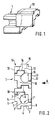
- the cross-section of the foundation stone 1 has an essentially L-shaped cross-sectional area, in that the main extension lines of a first and a second leg 2 and 3, as shown by the course of the outer sides of the Legs are given, are arranged at right angles to each other.
- the other facing sides of the legs 2, 3 result in a common arcuate surface 1 ', which forms a trough 1 ".
- the outer sides of the legs only have flat surface sections arranged at right angles to one another.
- the outer side of the leg facing away from the second leg 3 The first leg 2 has a recess 4, the outer side of the second leg 3 facing away from the first leg 2 has a corresponding protrusion 5.
- the free end 6 of the second leg 3 is formed by a protrusion 7 which is connected to that on the
- the projection 5, which is arranged on the outer side of this leg, is adjacent at right angles, as can be seen best in FIG. 1, the projections and recesses form uniform channels or strips running along the longitudinal extent of the base stone 1 out.
- a trough-shaped space extends between the legs in the longitudinal direction of the stones.
- the additional stone 10 also has an essentially L-shaped cross-sectional area and is composed of a first and a second leg 12 or 13, which adjoin one another at right angles. On the inner side of the first leg 12 facing the second leg 13 there is a recess 14 and on the outer side of this leg 12 facing away from the second leg 13 there is a projection 15 offset with respect to the recess.
- the inner and outer side of the second leg 13 and the boundary surface of its free end are each designed as flat surfaces 16, 17 and 18.
- the recesses 14 and the protrusion 15 of the additional stone 10 basically form channels and strips along the longitudinal extension of the additional stone, as in the case of foundation stone 1, as can be seen in FIG. 1.
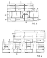
- the recess 14 and the projection 15 of the first leg 12 of the additional stone are complementary to the projection 7 at the free end 6 of the second leg 3 of the base stone 1 and to the recess 4 of the outer side of the first leg 2 of the base stone 1. These complementaries are in Engagement with one another when the foundation stones and additional stones are arranged in an alternating sequence one above the other to form a vertical wall structure, as shown in principle in FIG. 2.
- an additional stone 10 is placed as an intermediate stone between the base stone wall layers lying below and above, with the inner side of its - horizontal - first leg 12 from the free end 6 of the second - vertical - leg 3 of a base stone 1 arranged underneath.
- the second leg 13 of the additional stone 10 extends to the inside of the first leg 2 of the underlying base stone 1 and is supported there.
- a base stone 1 arranged above it is supported by the outer side of its first - horizontal - leg 2.
- a wall constructed in this way represents a form-fitting, rigid association of high stability and is suitable as a free-standing wall.
- the stones are secured in the bandage against shifting, even under the influence of thrust and pressure forces from any direction.
- the side wall of the wall for example as a closed vertical wall, can be formed.
- the flat surface 17, which forms the outward-facing side of the second leg 13 of the additional stone 10, is aligned with the boundary surface 8 at the free end of the first leg 2 of the upper and lower base element of the wall structure of FIG. 2. This results in this Side of the wall a flat closed side surface for the case of an execution of the wall structure, as shown in Fig. 3, consisting of foundation stones and additional stones in alternating rows arranged without gaps.
- an additional stone 10 ′ has a gate-like opening 23 in its second vertical leg 13. This provides access to the hollow interior, which is designed in the form of horizontal channels, and which results between the stones of a row of foundation stones and an additional row of stones supported thereon. This free access proves to be advantageous if lines are laid within the channels.
- the troughs 1 "(FIG. 2) can be partially filled with soil (which is preferably done in layers during the construction of the wall). Planting provided in the filled soil can then be carried out through the openings 23 grow out and receive light and water from there.
- a compensating stone 20 is arranged at the end of a row of additional stones, which, with an otherwise identical design as one of the other additional stones 10, has a smaller longitudinal extent than such. Furthermore, a compensation foundation stone 21 with a smaller longitudinal extent than one of the other foundation stones 1 used in the wall is also provided.
- each row of the base elements in each row of the base elements arranged groove-like recesses are present, which between the projection 5 of each base stone 1 of a row and the boundary surface 19 of the free end of the first - horizontal - leg 12 of each additional stone 10 of the row arranged below it.
- the back of the wall is composed of flat surface strips arranged between these channel-like recesses, each consisting of the flat surfaces 19 at the free ends of the first legs 12 of additional stones in a row and with these flush flat surfaces on the projections 5 on the outside of the second - vertical - Schen-Icel 3 are formed by foundation stones of a row arranged below.
- This "back” can also be used as a front if a structured surface is required.
- the entire rear side like the front side (FIG. 3) of this wall, can also be designed as a completely closed flat surface with a corresponding complementary design of the base stone 1 and / or the additional stone 10.
- the foundation and additional stones 1, 10 are each arranged in a row with the same gaps between stones 1 and 10, respectively.
- the stones 1, 10 stacked one above the other are each set to a gap, so that each stone 1 or 10, with its two ends of its longitudinal extent, lies on the ends of two stones 10 arranged below it or 1 supports by bridging the gap arranged between the ends of these two stones 10 and 1 respectively.
- the trough-like space or the trough 1 "arranged between the legs 2, 3 of a base stone is sometimes partially open to the outside, so that this interior of the base stones 1 can be filled with soil and planted with greenery Additional stones 10 'with a gate-like opening 23 (see FIG. 3) can of course also be used here, so that the ratio of the open, greenable area to the stone front of the wall is further improved.
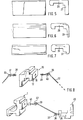
- cover plate 25 On the top row of the foundation stones of the wall in FIG. 4 there is a cover plate 25 with an identical cross-sectional configuration as the other additional stones 10 used as intermediate parts in the wall.
- This cover plate 25 is an additional stone with a longitudinal extension that is a multiple of the longitudinal extension a usual additional stone 10 or a foundation stone 1 corresponds.
- the cover plate 25 is optically advantageous in that it bridges the channel-like upper edge formed by the uppermost row of foundation stones.
- the cover plate 25 has a stabilizing effect.
- corresponding additional bricks with greater longitudinal extension can also be used in the lower rows of additional bricks in the wall structure in order to increase the stability of the wall or to bridge larger gaps between the bricks arranged underneath, for example to form passages or the like.
- FIGS. 5, 6 and 7. Three other versions of cover plates are shown in FIGS. 5, 6 and 7. These have a cross-sectional area modified in comparison to the additional stones of FIGS. 1 to 4. 5, planar outer sides of the legs 26, 27 are provided, that is to say that the projection 15 of an additional stone of FIG. 2 on the upper side of the plate is omitted. 6, the outer sides of the legs 28, 29 form a common arcuate surface. 7, the vertical leg is shortened in comparison to the embodiment of FIG. 5.
- the cover plate essentially consists of only one - horizontal - leg 30 and a vertical stub 31, so that when used, in contrast to the above-mentioned designs, the trough-shaped interior of the base stones of the top row remains open towards the front.
- the additional stone 10 with the cross-sectional configuration, as shown in FIGS. 1 to 4, and in particular the building block 25 provided as a cover plate in FIG. 4, is also advantageously used as the base or foundation stone of a wall structure.
- the second leg 13 is inserted vertically into the ground and forms an anchor.
- the outer side of the first leg 12 facing away from this second leg 13 and thus the upper side with its projection 15 forms the support for the bottom row of foundation stones of the wall structure. This eliminates the need for a footbed concreted on site, as is usually necessary, and the extended additional stone 25 is simply inserted into the ground.
- base stone can each be produced from an additional stone initially provided as an intermediate stone. If the base stone is to lie on a flat, for example cemented support surface, it is provided for its production that the second (vertical) leg of the additional stone is separated so that the originally inner side of the remaining first leg has a flat underside with recess 14. This flat underside of the stone then serves as a support surface for the base stone on the base. In this case there is no anchoring of the base stone in the underground.
- foundation stones 1 and additional stones 10 of a wall structure as shown in FIG. 8, or the like in their outwardly facing sides with dowels 41, 38, 39, 35 and screw eyelets 42, 47, 40, 36. be provided, which serve as a fastening device for engaging an anchoring cable 32 which engages with its one end provided with a hook 33 in the eyelet 42, 37, 40 arranged on a foundation stone 1 or additional stone 10 of the wall structure and is fixed elsewhere with its other end, for example in the anchor-like, otherwise firmly hooked-in intermediate piece 45, as shown in FIG. 8.
Landscapes
- Engineering & Computer Science (AREA)
- Architecture (AREA)
- Civil Engineering (AREA)
- Structural Engineering (AREA)
- Physics & Mathematics (AREA)
- Electromagnetism (AREA)
- Finishing Walls (AREA)
- Revetment (AREA)
- Retaining Walls (AREA)
- Fencing (AREA)
Priority Applications (6)
| Application Number | Priority Date | Filing Date | Title |
|---|---|---|---|
| DE8383110449T DE3374884D1 (en) | 1983-10-20 | 1983-10-20 | Set of stones for vertical composite walls |
| AT83110449T ATE31337T1 (de) | 1983-10-20 | 1983-10-20 | Steinsatz fuer senkrechten mauerverbund. |
| EP83110449A EP0139031B1 (de) | 1983-10-20 | 1983-10-20 | Steinsatz für senkrechten Mauerverbund |
| US06/659,407 US4596103A (en) | 1983-10-20 | 1984-10-10 | Stone set for vertical wall assemblies |
| JP59218774A JPS60173240A (ja) | 1983-10-20 | 1984-10-19 | 本質的に垂直な壁結合体を形成するための石セツト |
| CA000465845A CA1225246A (en) | 1983-10-20 | 1984-10-19 | Stone set for vertical wall assemblies |
Applications Claiming Priority (1)
| Application Number | Priority Date | Filing Date | Title |
|---|---|---|---|
| EP83110449A EP0139031B1 (de) | 1983-10-20 | 1983-10-20 | Steinsatz für senkrechten Mauerverbund |
Publications (2)
| Publication Number | Publication Date |
|---|---|
| EP0139031A1 EP0139031A1 (de) | 1985-05-02 |
| EP0139031B1 true EP0139031B1 (de) | 1987-12-09 |
Family
ID=8190764
Family Applications (1)
| Application Number | Title | Priority Date | Filing Date |
|---|---|---|---|
| EP83110449A Expired EP0139031B1 (de) | 1983-10-20 | 1983-10-20 | Steinsatz für senkrechten Mauerverbund |
Country Status (6)
| Country | Link |
|---|---|
| US (1) | US4596103A (cs) |
| EP (1) | EP0139031B1 (cs) |
| JP (1) | JPS60173240A (cs) |
| AT (1) | ATE31337T1 (cs) |
| CA (1) | CA1225246A (cs) |
| DE (1) | DE3374884D1 (cs) |
Families Citing this family (5)
| Publication number | Priority date | Publication date | Assignee | Title |
|---|---|---|---|---|
| US4860505A (en) * | 1988-05-26 | 1989-08-29 | Bender David C | Construction block |
| US5765970A (en) * | 1996-06-17 | 1998-06-16 | Fox; James C. | Plastic retaining wall construction |
| DE10154369A1 (de) * | 2001-11-06 | 2003-05-22 | Kuebler Hanns H | Bepflanzbare, schalldämmende Formen |
| WO2011144764A2 (es) * | 2010-05-21 | 2011-11-24 | Medina Guillen Juan Carlos | Sistema de fabricación de muros |
| USD1057206S1 (en) * | 2022-11-07 | 2025-01-07 | Westblock Systems, Inc. | Wall block |
Family Cites Families (5)
| Publication number | Priority date | Publication date | Assignee | Title |
|---|---|---|---|---|
| US1687342A (en) * | 1926-05-12 | 1928-10-09 | Macveigh John Gerald | Building tile |
| DE971377C (de) * | 1951-12-30 | 1959-01-15 | Wilhelm Steinhage | Mehrschalige Wand und Bausteine hierzu |
| EP0059820B1 (de) * | 1981-03-10 | 1984-05-16 | Rolf Scheiwiller | Bausatz zur Erstellung von Mauern |
| US4426176A (en) * | 1981-08-10 | 1984-01-17 | Tokuyama Soda Co., Ltd. | L-Shaped concrete block and method for constructing a retaining wall by such L-shaped concrete blocks |
| DE3138155A1 (de) * | 1981-09-25 | 1983-04-14 | Couwenbergs, Paul, Dr., 7500 Karlsruhe | Stein, insbesondere kunststein |
-
1983
- 1983-10-20 DE DE8383110449T patent/DE3374884D1/de not_active Expired
- 1983-10-20 AT AT83110449T patent/ATE31337T1/de not_active IP Right Cessation
- 1983-10-20 EP EP83110449A patent/EP0139031B1/de not_active Expired
-
1984
- 1984-10-10 US US06/659,407 patent/US4596103A/en not_active Expired - Fee Related
- 1984-10-19 CA CA000465845A patent/CA1225246A/en not_active Expired
- 1984-10-19 JP JP59218774A patent/JPS60173240A/ja active Granted
Also Published As
| Publication number | Publication date |
|---|---|
| JPS60173240A (ja) | 1985-09-06 |
| CA1225246A (en) | 1987-08-11 |
| EP0139031A1 (de) | 1985-05-02 |
| DE3374884D1 (en) | 1988-01-21 |
| US4596103A (en) | 1986-06-24 |
| JPH0451619B2 (cs) | 1992-08-19 |
| ATE31337T1 (de) | 1987-12-15 |
Similar Documents
| Publication | Publication Date | Title |
|---|---|---|
| DE2731228C2 (de) | Formstein aus Beton für die Herstellung einer Stützmauer sowie aus derartigen Formsteinen hergestellte Stützmauer | |
| EP0059820A1 (de) | Bausatz zur Erstellung von Mauern | |
| DE3344974A1 (de) | Boeschungsstein sowie verfahren zum aufbau einer damit erstellten hangbefestigung | |
| DE2519232C3 (de) | Bepflanzbare Stützmauer | |
| EP0322668A1 (de) | Bauelement zum Aufbau einer Mauer und Mauer aufgebaut mit den Bauelementen | |
| EP0234175A1 (de) | Bausatz zur Erstellung von Mauerwerken | |
| EP0139031B1 (de) | Steinsatz für senkrechten Mauerverbund | |
| DE10043609C1 (de) | Mauerwerk | |
| DE2844629A1 (de) | Vorgefertigtes bauelement fuer mauern | |
| EP0469008B1 (de) | Mauer | |
| EP0016727B1 (de) | Bausatz aus Verbundsteinen, insbesondere für die Hangsicherung und Flussbettverbauung | |
| EP0034565A1 (de) | Mauer in Elementbauweise | |
| AT360574B (de) | Stuetz- und futtermauer | |
| DE2826324A1 (de) | Stuetzwand, bestehend aus einem aus beton-fertigteilen zusammengesetzten raumgitter, dessen hohlraeume mit schuettgut verfuellt sind | |
| DE102010010046A1 (de) | Pflanztrog als anreihbares Modul | |
| DE3816127A1 (de) | Bepflanzbare laermschutzwand | |
| AT387807B (de) | Bauelementsystem | |
| DE3837243A1 (de) | Formstein fuer eine bepflanzbare boeschungssicherung | |
| DE2313316A1 (de) | Quaderfoermiger schalungsstein fuer tragende wandungen | |
| DE2002406C3 (de) | Im Erdreich versenkt angeordnetes Schwimmbecken, dessen Wand oben an einem Widerlager horizontal abgestützt ist | |
| DE1810012A1 (de) | Betonfertigteile zur Strassenbefestigung | |
| EP0860550A2 (de) | Vorrichtung für die Anpflanzung von Bäumen und dergleichen | |
| DE3501147C2 (de) | Werkstein | |
| EP0954639B1 (de) | Formstein-bausatz | |
| DE3231000C2 (de) | Betonring zur Bildung von Mauern und seine Verwendung |
Legal Events
| Date | Code | Title | Description |
|---|---|---|---|
| PUAI | Public reference made under article 153(3) epc to a published international application that has entered the european phase |
Free format text: ORIGINAL CODE: 0009012 |
|
| AK | Designated contracting states |
Designated state(s): AT BE CH DE FR GB IT LI NL SE |
|
| 17P | Request for examination filed |
Effective date: 19851003 |
|
| 17Q | First examination report despatched |
Effective date: 19870423 |
|
| GRAA | (expected) grant |
Free format text: ORIGINAL CODE: 0009210 |
|
| AK | Designated contracting states |
Kind code of ref document: B1 Designated state(s): AT BE CH DE FR GB IT LI NL SE |
|
| REF | Corresponds to: |
Ref document number: 31337 Country of ref document: AT Date of ref document: 19871215 Kind code of ref document: T |
|
| REF | Corresponds to: |
Ref document number: 3374884 Country of ref document: DE Date of ref document: 19880121 |
|
| ET | Fr: translation filed | ||
| ITF | It: translation for a ep patent filed | ||
| GBT | Gb: translation of ep patent filed (gb section 77(6)(a)/1977) | ||
| PLBE | No opposition filed within time limit |
Free format text: ORIGINAL CODE: 0009261 |
|
| STAA | Information on the status of an ep patent application or granted ep patent |
Free format text: STATUS: NO OPPOSITION FILED WITHIN TIME LIMIT |
|
| 26N | No opposition filed | ||
| ITTA | It: last paid annual fee | ||
| PGFP | Annual fee paid to national office [announced via postgrant information from national office to epo] |
Ref country code: SE Payment date: 19911014 Year of fee payment: 9 |
|
| PG25 | Lapsed in a contracting state [announced via postgrant information from national office to epo] |
Ref country code: SE Effective date: 19921021 |
|
| EUG | Se: european patent has lapsed |
Ref document number: 83110449.2 Effective date: 19930510 |
|
| PGFP | Annual fee paid to national office [announced via postgrant information from national office to epo] |
Ref country code: GB Payment date: 19971015 Year of fee payment: 15 |
|
| PGFP | Annual fee paid to national office [announced via postgrant information from national office to epo] |
Ref country code: FR Payment date: 19971017 Year of fee payment: 15 Ref country code: BE Payment date: 19971017 Year of fee payment: 15 |
|
| PGFP | Annual fee paid to national office [announced via postgrant information from national office to epo] |
Ref country code: NL Payment date: 19971031 Year of fee payment: 15 Ref country code: AT Payment date: 19971031 Year of fee payment: 15 |
|
| PGFP | Annual fee paid to national office [announced via postgrant information from national office to epo] |
Ref country code: CH Payment date: 19971231 Year of fee payment: 15 |
|
| PG25 | Lapsed in a contracting state [announced via postgrant information from national office to epo] |
Ref country code: GB Free format text: LAPSE BECAUSE OF NON-PAYMENT OF DUE FEES Effective date: 19981020 Ref country code: AT Free format text: LAPSE BECAUSE OF NON-PAYMENT OF DUE FEES Effective date: 19981020 |
|
| PGFP | Annual fee paid to national office [announced via postgrant information from national office to epo] |
Ref country code: DE Payment date: 19981020 Year of fee payment: 16 |
|
| PG25 | Lapsed in a contracting state [announced via postgrant information from national office to epo] |
Ref country code: LI Free format text: LAPSE BECAUSE OF NON-PAYMENT OF DUE FEES Effective date: 19981031 Ref country code: CH Free format text: LAPSE BECAUSE OF NON-PAYMENT OF DUE FEES Effective date: 19981031 Ref country code: BE Free format text: LAPSE BECAUSE OF NON-PAYMENT OF DUE FEES Effective date: 19981031 |
|
| BERE | Be: lapsed |
Owner name: COUWENBERGS PAUL Effective date: 19981031 |
|
| PG25 | Lapsed in a contracting state [announced via postgrant information from national office to epo] |
Ref country code: NL Free format text: LAPSE BECAUSE OF NON-PAYMENT OF DUE FEES Effective date: 19990501 |
|
| GBPC | Gb: european patent ceased through non-payment of renewal fee |
Effective date: 19981020 |
|
| REG | Reference to a national code |
Ref country code: CH Ref legal event code: PL |
|
| PG25 | Lapsed in a contracting state [announced via postgrant information from national office to epo] |
Ref country code: FR Free format text: LAPSE BECAUSE OF NON-PAYMENT OF DUE FEES Effective date: 19990630 |
|
| NLV4 | Nl: lapsed or anulled due to non-payment of the annual fee |
Effective date: 19990501 |
|
| REG | Reference to a national code |
Ref country code: FR Ref legal event code: ST |
|
| PG25 | Lapsed in a contracting state [announced via postgrant information from national office to epo] |
Ref country code: DE Free format text: LAPSE BECAUSE OF NON-PAYMENT OF DUE FEES Effective date: 20000801 |