EP0137425B1 - Verfahren zur Auswertung eines Subcodes - Google Patents
Verfahren zur Auswertung eines Subcodes Download PDFInfo
- Publication number
- EP0137425B1 EP0137425B1 EP84111588A EP84111588A EP0137425B1 EP 0137425 B1 EP0137425 B1 EP 0137425B1 EP 84111588 A EP84111588 A EP 84111588A EP 84111588 A EP84111588 A EP 84111588A EP 0137425 B1 EP0137425 B1 EP 0137425B1
- Authority
- EP
- European Patent Office
- Prior art keywords
- data
- register
- read
- code
- period
- Prior art date
- Legal status (The legal status is an assumption and is not a legal conclusion. Google has not performed a legal analysis and makes no representation as to the accuracy of the status listed.)
- Expired
Links
- 238000000034 method Methods 0.000 title claims description 12
- 238000001514 detection method Methods 0.000 description 6
- 238000011156 evaluation Methods 0.000 description 6
- 238000010998 test method Methods 0.000 description 4
- 238000013479 data entry Methods 0.000 description 3
- 230000005540 biological transmission Effects 0.000 description 1
- 230000003139 buffering effect Effects 0.000 description 1
- 238000012937 correction Methods 0.000 description 1
- 125000004122 cyclic group Chemical group 0.000 description 1
- 238000010586 diagram Methods 0.000 description 1
- 230000004807 localization Effects 0.000 description 1
- 230000005236 sound signal Effects 0.000 description 1
- 230000001360 synchronised effect Effects 0.000 description 1
- 238000012360 testing method Methods 0.000 description 1
Images
Classifications
-
- G—PHYSICS
- G11—INFORMATION STORAGE
- G11B—INFORMATION STORAGE BASED ON RELATIVE MOVEMENT BETWEEN RECORD CARRIER AND TRANSDUCER
- G11B27/00—Editing; Indexing; Addressing; Timing or synchronising; Monitoring; Measuring tape travel
- G11B27/10—Indexing; Addressing; Timing or synchronising; Measuring tape travel
- G11B27/19—Indexing; Addressing; Timing or synchronising; Measuring tape travel by using information detectable on the record carrier
- G11B27/28—Indexing; Addressing; Timing or synchronising; Measuring tape travel by using information detectable on the record carrier by using information signals recorded by the same method as the main recording
- G11B27/30—Indexing; Addressing; Timing or synchronising; Measuring tape travel by using information detectable on the record carrier by using information signals recorded by the same method as the main recording on the same track as the main recording
- G11B27/3027—Indexing; Addressing; Timing or synchronising; Measuring tape travel by using information detectable on the record carrier by using information signals recorded by the same method as the main recording on the same track as the main recording used signal is digitally coded
- G11B27/3063—Subcodes
-
- G—PHYSICS
- G11—INFORMATION STORAGE
- G11B—INFORMATION STORAGE BASED ON RELATIVE MOVEMENT BETWEEN RECORD CARRIER AND TRANSDUCER
- G11B20/00—Signal processing not specific to the method of recording or reproducing; Circuits therefor
- G11B20/10—Digital recording or reproducing
- G11B20/10527—Audio or video recording; Data buffering arrangements
-
- G—PHYSICS
- G11—INFORMATION STORAGE
- G11B—INFORMATION STORAGE BASED ON RELATIVE MOVEMENT BETWEEN RECORD CARRIER AND TRANSDUCER
- G11B20/00—Signal processing not specific to the method of recording or reproducing; Circuits therefor
- G11B20/10—Digital recording or reproducing
- G11B20/12—Formatting, e.g. arrangement of data block or words on the record carriers
-
- G—PHYSICS
- G11—INFORMATION STORAGE
- G11B—INFORMATION STORAGE BASED ON RELATIVE MOVEMENT BETWEEN RECORD CARRIER AND TRANSDUCER
- G11B20/00—Signal processing not specific to the method of recording or reproducing; Circuits therefor
- G11B20/10—Digital recording or reproducing
- G11B20/18—Error detection or correction; Testing, e.g. of drop-outs
- G11B20/1803—Error detection or correction; Testing, e.g. of drop-outs by redundancy in data representation
-
- G—PHYSICS
- G11—INFORMATION STORAGE
- G11B—INFORMATION STORAGE BASED ON RELATIVE MOVEMENT BETWEEN RECORD CARRIER AND TRANSDUCER
- G11B20/00—Signal processing not specific to the method of recording or reproducing; Circuits therefor
- G11B20/10—Digital recording or reproducing
- G11B20/18—Error detection or correction; Testing, e.g. of drop-outs
- G11B20/1806—Pulse code modulation systems for audio signals
- G11B20/1809—Pulse code modulation systems for audio signals by interleaving
-
- G—PHYSICS
- G11—INFORMATION STORAGE
- G11B—INFORMATION STORAGE BASED ON RELATIVE MOVEMENT BETWEEN RECORD CARRIER AND TRANSDUCER
- G11B20/00—Signal processing not specific to the method of recording or reproducing; Circuits therefor
- G11B20/10—Digital recording or reproducing
- G11B20/12—Formatting, e.g. arrangement of data block or words on the record carriers
- G11B20/1217—Formatting, e.g. arrangement of data block or words on the record carriers on discs
-
- G—PHYSICS
- G11—INFORMATION STORAGE
- G11B—INFORMATION STORAGE BASED ON RELATIVE MOVEMENT BETWEEN RECORD CARRIER AND TRANSDUCER
- G11B2220/00—Record carriers by type
- G11B2220/20—Disc-shaped record carriers
- G11B2220/25—Disc-shaped record carriers characterised in that the disc is based on a specific recording technology
- G11B2220/2537—Optical discs
- G11B2220/2545—CDs
Definitions
- the invention relates to a method for evaluating a control code word consisting of a plurality of code elements when reproducing digitized audio or video information recorded on a disc-shaped carrier, each code element containing control information independent of the other code elements and the information of the control code word being ignored during the evaluation if an error is found in the accuracy check.
- control code words are also recorded during recording. These are used to store data that has a meaningful relationship to the actual storage data, e.g. stand by the stored music program. It is information that is not intended for the actual audio transmission.
- So z. B. the so-called Q-channel of a control code word for the operation and display of a compact disc device.
- the control code words are divided into so-called blocks and these into code elements.
- the Q-channel consists of 96 bits plus two synchronous BITS and contains information about the title number, the running time of a piece of music in minutes and seconds or provides information about the content of the audio disc.
- the information bits of the code elements are nested embedded in the data BITS of the audio program. To maintain sufficient redundancy, 75 blocks are scanned per second. In this way, a continuous flow of information about the code data is possible during the playback of a music program.
- 16 parity BITS are appended to the 80 data BITS of a block in order to be able to detect information errors on the playback side. Errors can be identified using the CRC (cyclic redundancy check) method.
- the parity BITS are added to the data BITS in such a way that with the help of the CRC, i.e. that after dividing the block content by a given generator polynomial G (x), a quotient without a remainder must come out.
- the CRC test method When evaluating the accumulated time e.g. the other code elements of the data block are of no interest. However, if there are BIT errors in these code elements, the CRC test method detects an error in the entire block, so that no information is available because the CRC method does not allow the test to be divided within the block. With this method, a trouble-free evaluation is not always possible. In addition, the CRC test method requires a considerable amount of computation, since the division polynomial must continuously perform the division operation.
- the invention has for its object to simplify the test method and largely exclude the possibility of interference. According to the invention, this object is achieved by the measures specified in the patent claim.
- the invention is based on the finding that, when evaluating each code element, there are disproportionately fewer disruptions in relation to the evaluation than when evaluating the entire block.
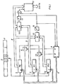
- An interesting code element 2 to be evaluated is extracted from the sub-code word 1.
- the data BITS of this selected code element are read into a first register 3 (R a ).
- a control circuit 4 activates this register via a data line 5.
- the output A of the control circuit 4 transmits a gate 6 so that the data reach the register 7 (R 1 ) activated via the line 5.
- First read-in period. Thereupon new data are written into the first register 3 (R o ).
- the control circuit 4 brings the in the two registers 3 (R o ) and 7 (R 1 ) stored data via the data lines 8 and 9 to a comparison stage 10.
- the error detection circuit 11 If the result is positive, that is to say in the event of equality, the error detection circuit 11 outputs a signal to the stage 12 which contains the data switched through from register 3 for evaluation. If the comparison turns out negative, the error detection circuit 11 blocks the stage 12 and at the same time gives a signal to the control circuit 4, after which the control circuit 4 opens the gate 13 via its output B, after which those read in the first register 3 (R o ) Data get into the register 14 (R 2 ) activated by the control circuit 4 via the line 5. The currently read in new data in register 3 (R o ) are compared with the last data read in in register 14 (R 2 ) in comparison stage 15. If the comparison is negative, a signal is sent to the control circuit 4 via the error detection circuit 16.
- the comparison takes place via comparison level 10. If the result is positive, stage 12 for switching the data is enabled via error detection circuit 11. If the result is negative, the error detection circuit 11 generates a signal for the control circuit 4, which releases the register 7 (R 1 ), so that the current data of the third read-in period from the register 3 (R o ) are written in via the opened gate 6 a subsequent comparison from the fourth reading period is available in comparison stage 10.
- the effort described with the aid of FIG. 1 can be reduced by a suitable combination of the comparison stages 10 and 15 and the error detection circuit 11 and 16 to form a single circuit controlled by the control circuit 4.
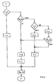
- the method just described is recorded in the form of a flow chart.
- the read data are overwritten by the entry register R o in the first register R 1 .
- the method described with the aid of FIG. 1 relates to a three-way comparison of data of a code element read in one after the other. If the accuracy requirements are not so high, a two-way comparison of data from two successive code elements can also be carried out, as a result of which the effort for implementing the method can be reduced considerably.
Landscapes
- Engineering & Computer Science (AREA)
- Signal Processing (AREA)
- Multimedia (AREA)
- Signal Processing For Digital Recording And Reproducing (AREA)
- Error Detection And Correction (AREA)
- Detection And Correction Of Errors (AREA)
- Optical Recording Or Reproduction (AREA)
Applications Claiming Priority (2)
| Application Number | Priority Date | Filing Date | Title |
|---|---|---|---|
| DE3336747A DE3336747C2 (de) | 1983-10-08 | 1983-10-08 | Verfahren zur Auswertung eines aus mehreren Codeelementen bestehenden Steuercodewortes |
| DE3336747 | 1983-10-08 |
Publications (2)
| Publication Number | Publication Date |
|---|---|
| EP0137425A1 EP0137425A1 (de) | 1985-04-17 |
| EP0137425B1 true EP0137425B1 (de) | 1988-12-07 |
Family
ID=6211410
Family Applications (1)
| Application Number | Title | Priority Date | Filing Date |
|---|---|---|---|
| EP84111588A Expired EP0137425B1 (de) | 1983-10-08 | 1984-09-28 | Verfahren zur Auswertung eines Subcodes |
Country Status (8)
| Country | Link |
|---|---|
| US (1) | US4852105A (da) |
| EP (1) | EP0137425B1 (da) |
| JP (1) | JPS61500390A (da) |
| DE (2) | DE3336747C2 (da) |
| DK (1) | DK257185A (da) |
| HK (1) | HK140893A (da) |
| IE (1) | IE55776B1 (da) |
| WO (1) | WO1985001824A1 (da) |
Families Citing this family (18)
| Publication number | Priority date | Publication date | Assignee | Title |
|---|---|---|---|---|
| DE3704898A1 (de) * | 1986-02-20 | 1987-08-27 | Sharp Kk | Diskettenaufzeichnungs-pruefverfahren |
| JPS63127469A (ja) * | 1986-11-18 | 1988-05-31 | Sony Corp | 記録可能型光デイスク記録再生装置 |
| DE3801123A1 (de) * | 1988-01-16 | 1989-07-27 | Philips Patentverwaltung | Vermittlungsanlage |
| CZ284768B6 (cs) * | 1988-01-19 | 1999-02-17 | Philips Electronics N. V. | Způsob přenosu informačních signálů a zařízení pro jeho provádění |
| JPH07118798B2 (ja) * | 1988-02-29 | 1995-12-18 | パイオニア株式会社 | 画像情報の記録方法及び再生方法 |
| JP2938077B2 (ja) * | 1988-03-11 | 1999-08-23 | パイオニア株式会社 | 画像信号の記録方法及び画像の再生方法 |
| JP2778169B2 (ja) * | 1989-12-30 | 1998-07-23 | ソニー株式会社 | デイジタル信号処理回路 |
| JP2803351B2 (ja) * | 1990-09-14 | 1998-09-24 | 日本電気株式会社 | 多数決回路 |
| WO1992012481A1 (en) * | 1990-12-27 | 1992-07-23 | Motorola, Inc. | Wireless personal communication system |
| DE4133965A1 (de) * | 1991-10-14 | 1993-04-15 | Standard Elektrik Lorenz Ag | Abstraktor |
| WO1993026104A1 (en) * | 1992-06-05 | 1993-12-23 | Smart Tag Systems, Inc. | Device and method for detection of intermittently repeating information |
| US5592404A (en) * | 1993-11-04 | 1997-01-07 | Cirrus Logic, Inc. | Versatile error correction system |
| GB2333886B (en) * | 1995-06-23 | 2000-01-12 | Sony Corp | Device for reproducing a recording medium having plural recording areas |
| JP3521552B2 (ja) * | 1995-06-23 | 2004-04-19 | ソニー株式会社 | 再生装置 |
| US5691723A (en) * | 1995-09-11 | 1997-11-25 | E-Systems, Inc. | Apparatus and method for encoding and decoding data on tactical air navigation and distance measuring equipment signals |
| US5870406A (en) * | 1997-02-19 | 1999-02-09 | Ericsson Inc. | Automatic repeat request(ARQ) data communications method and apparatus |
| JP3534629B2 (ja) * | 1998-12-10 | 2004-06-07 | 株式会社三協精機製作所 | 磁気記録データの復調方法 |
| US9715420B2 (en) * | 2015-01-21 | 2017-07-25 | International Business Machines Corporation | String dataflow error detection |
Citations (1)
| Publication number | Priority date | Publication date | Assignee | Title |
|---|---|---|---|---|
| DE3130145A1 (de) * | 1980-07-31 | 1982-03-11 | Hitachi, Ltd., Tokyo | Schnittstellensteuersystem |
Family Cites Families (11)
| Publication number | Priority date | Publication date | Assignee | Title |
|---|---|---|---|---|
| GB1575002A (en) * | 1976-03-11 | 1980-09-17 | Post Office | Data transmission system |
| FR2435776A1 (fr) * | 1978-09-08 | 1980-04-04 | Charbonnages De France | Enregistreur-lecteur de signaux sur bande magnetique et procede de traitement de signaux mis en oeuvre dans cet enregistreur-lecteur |
| IT1121390B (it) * | 1979-06-12 | 1986-04-02 | Telettra Lab Telefon | Telaio universale per l'alloggiamento di apparecchiature di telecomunicazioni |
| FR2458874A1 (fr) * | 1979-06-13 | 1981-01-02 | France Etat | Systeme d'enregistrement d'informations de pietage sur une bande magnetique de magnetoscope |
| US4375101A (en) * | 1980-09-30 | 1983-02-22 | Video Education, Inc. | System for formatting data on video tape for high accuracy recovery |
| JPS57198586A (en) * | 1981-05-28 | 1982-12-06 | Sony Corp | Digital disc reproducing device |
| JPS5848279A (ja) * | 1981-09-14 | 1983-03-22 | Sony Corp | キユ−信号処理装置 |
| US4518947A (en) * | 1981-09-28 | 1985-05-21 | E-Systems, Inc. | Apparatus for decoding redundant interleaved data |
| JPS58133689A (ja) * | 1982-02-02 | 1983-08-09 | Sony Corp | デイジタルオ−デイオデイスク装置 |
| NL8200560A (nl) * | 1982-02-15 | 1983-09-01 | Philips Nv | Stelsel voor kommunikatie middels herhaald uitgezonden berichten alsmede stations voor gebruik in zo een stelsel. |
| US4577332A (en) * | 1983-03-14 | 1986-03-18 | General Electric Company | Digital decoding arrangement |
-
1983
- 1983-10-08 DE DE3336747A patent/DE3336747C2/de not_active Expired
-
1984
- 1984-09-28 DE DE8484111588T patent/DE3475582D1/de not_active Expired
- 1984-09-28 EP EP84111588A patent/EP0137425B1/de not_active Expired
- 1984-09-28 WO PCT/EP1984/000296 patent/WO1985001824A1/de not_active Ceased
- 1984-09-28 JP JP59503661A patent/JPS61500390A/ja active Pending
- 1984-10-05 IE IE2562/84A patent/IE55776B1/en not_active IP Right Cessation
-
1985
- 1985-06-07 US US06/742,619 patent/US4852105A/en not_active Expired - Lifetime
- 1985-06-07 DK DK257185A patent/DK257185A/da not_active Application Discontinuation
-
1993
- 1993-12-23 HK HK1408/93A patent/HK140893A/xx not_active IP Right Cessation
Patent Citations (1)
| Publication number | Priority date | Publication date | Assignee | Title |
|---|---|---|---|---|
| DE3130145A1 (de) * | 1980-07-31 | 1982-03-11 | Hitachi, Ltd., Tokyo | Schnittstellensteuersystem |
Non-Patent Citations (1)
| Title |
|---|
| Lesea/Zaks: Mikroprozessor Interface Techniken, 4. Aufl. 1982, pp. 328-332 * |
Also Published As
| Publication number | Publication date |
|---|---|
| DK257185D0 (da) | 1985-06-07 |
| IE55776B1 (en) | 1991-01-16 |
| WO1985001824A1 (fr) | 1985-04-25 |
| JPS61500390A (ja) | 1986-03-06 |
| IE842562L (en) | 1985-04-08 |
| EP0137425A1 (de) | 1985-04-17 |
| DE3336747A1 (de) | 1985-05-02 |
| HK140893A (en) | 1993-12-31 |
| DE3475582D1 (en) | 1989-01-12 |
| DK257185A (da) | 1985-06-07 |
| US4852105A (en) | 1989-07-25 |
| DE3336747C2 (de) | 1985-11-28 |
Similar Documents
| Publication | Publication Date | Title |
|---|---|---|
| EP0137425B1 (de) | Verfahren zur Auswertung eines Subcodes | |
| DE3783623T2 (de) | Programmauswahl fuer eine digitale tonplatte. | |
| DE3704898C2 (da) | ||
| DE3687156T2 (de) | Anordnung zur informationsaufzeichnung und wiedergabe. | |
| DE19542958A1 (de) | Datenaufzeichnungsmedium-Verwaltungsverfahren, Datenaufzeichnungsmedium-Verwaltungsvorrichtung und Datenaufzeichnungsmedium | |
| DE3131413A1 (de) | Verfahren und vorrichtung zum erfassen eines edierpunktes auf einem aufzeichnungsmedium | |
| DE1295246B (de) | Schaltungsanordnung zur fehlergesicherten Wiedergabe von parallel dargestellten digitalen Signalen | |
| DE68929165T2 (de) | Gerät zur magnetischen Aufnahme und Wiedergabe und Verfahren zur Aufnahme und Wiedergabe | |
| DE2944177A1 (de) | Informationssystem ueber saemtliche funktionen eines musikautomaten | |
| DE4445013A1 (de) | Erschütterungsresistentes Abspielgerät mit verbesserter Synchronisation | |
| DE3238077A1 (de) | Verfahren und schaltungsanordnungen zum auffinden und auswerten von fehlstellen auf aufzeichnungstraegern mit in wenigstens einer spur aufgezeichneten digitalsignalen | |
| EP0144831B1 (de) | Geräteanordnung zur Fehlerermittlung bei plattenförmigen Informationsträgern | |
| DE3820590C2 (de) | Verfahren zum Ermitteln von leeren Bereichen auf einem Aufzeichnungsträger | |
| DE3888126T2 (de) | Gerät und Methode zur Aufzeichnung eines digitalen Signals. | |
| DE3045609A1 (de) | Verfahren und schaltungsanordnung zur abgabe einer korrigierten datengruppe an eine bestimmungsschaltung | |
| DE4007814A1 (de) | Verfahren zur aufzeichnung und wiedergabe von digitalen daten auf einem aufzeichnungstraeger | |
| EP0037487B1 (de) | Verfahren und Gerät zum Auffinden eines Speicherplatzes auf einem Aufzeichnungsträger | |
| DE4204122C2 (de) | Verfahren zum Verhindern einer fehlerhaften Aufzeichnung in einem CD-Gerät | |
| DE69516969T2 (de) | Datenwiedergabe | |
| DE68920116T2 (de) | Redigiersystem für Adressentafeln. | |
| DE2921544C2 (de) | Steuerschaltung zum Einschreiben und Lesen von Datensätzen für Speichereinrichtungen mit umlaufenden Datenspeichern | |
| DE69019432T2 (de) | Dekodierungsanordnung. | |
| US4696008A (en) | Data storing device having position determining means | |
| DE19850020A1 (de) | Gerät zum Abspielen von auf einer optischen Informationsplatte digital gespeicherten Informationen | |
| WO1992022064A1 (de) | Fehlerartsignalisation optischer informationsträger |
Legal Events
| Date | Code | Title | Description |
|---|---|---|---|
| PUAI | Public reference made under article 153(3) epc to a published international application that has entered the european phase |
Free format text: ORIGINAL CODE: 0009012 |
|
| AK | Designated contracting states |
Designated state(s): BE CH DE FR GB IT LI LU NL SE |
|
| 17P | Request for examination filed |
Effective date: 19850919 |
|
| 17Q | First examination report despatched |
Effective date: 19861118 |
|
| ITF | It: translation for a ep patent filed | ||
| GRAA | (expected) grant |
Free format text: ORIGINAL CODE: 0009210 |
|
| AK | Designated contracting states |
Kind code of ref document: B1 Designated state(s): BE CH DE FR GB IT LI LU NL SE |
|
| GBT | Gb: translation of ep patent filed (gb section 77(6)(a)/1977) | ||
| REF | Corresponds to: |
Ref document number: 3475582 Country of ref document: DE Date of ref document: 19890112 |
|
| ET | Fr: translation filed | ||
| PLBE | No opposition filed within time limit |
Free format text: ORIGINAL CODE: 0009261 |
|
| STAA | Information on the status of an ep patent application or granted ep patent |
Free format text: STATUS: NO OPPOSITION FILED WITHIN TIME LIMIT |
|
| 26N | No opposition filed | ||
| ITTA | It: last paid annual fee | ||
| PGFP | Annual fee paid to national office [announced via postgrant information from national office to epo] |
Ref country code: LU Payment date: 19920820 Year of fee payment: 9 |
|
| PGFP | Annual fee paid to national office [announced via postgrant information from national office to epo] |
Ref country code: BE Payment date: 19920909 Year of fee payment: 9 |
|
| PGFP | Annual fee paid to national office [announced via postgrant information from national office to epo] |
Ref country code: SE Payment date: 19920917 Year of fee payment: 9 |
|
| PGFP | Annual fee paid to national office [announced via postgrant information from national office to epo] |
Ref country code: CH Payment date: 19920929 Year of fee payment: 9 |
|
| PGFP | Annual fee paid to national office [announced via postgrant information from national office to epo] |
Ref country code: NL Payment date: 19920930 Year of fee payment: 9 |
|
| EPTA | Lu: last paid annual fee | ||
| PG25 | Lapsed in a contracting state [announced via postgrant information from national office to epo] |
Ref country code: LU Free format text: LAPSE BECAUSE OF NON-PAYMENT OF DUE FEES Effective date: 19930928 |
|
| PG25 | Lapsed in a contracting state [announced via postgrant information from national office to epo] |
Ref country code: SE Effective date: 19930929 |
|
| PG25 | Lapsed in a contracting state [announced via postgrant information from national office to epo] |
Ref country code: LI Effective date: 19930930 Ref country code: CH Effective date: 19930930 Ref country code: BE Effective date: 19930930 |
|
| BERE | Be: lapsed |
Owner name: DEUTSCHE THOMSON-BRANDT G.M.B.H. Effective date: 19930930 |
|
| PG25 | Lapsed in a contracting state [announced via postgrant information from national office to epo] |
Ref country code: NL Effective date: 19940401 |
|
| NLV4 | Nl: lapsed or anulled due to non-payment of the annual fee | ||
| REG | Reference to a national code |
Ref country code: CH Ref legal event code: PL |
|
| EUG | Se: european patent has lapsed |
Ref document number: 84111588.4 Effective date: 19940410 |
|
| REG | Reference to a national code |
Ref country code: GB Ref legal event code: 746 Effective date: 19970822 |
|
| REG | Reference to a national code |
Ref country code: FR Ref legal event code: D6 |
|
| REG | Reference to a national code |
Ref country code: GB Ref legal event code: IF02 |
|
| PGFP | Annual fee paid to national office [announced via postgrant information from national office to epo] |
Ref country code: GB Payment date: 20030710 Year of fee payment: 20 |
|
| PGFP | Annual fee paid to national office [announced via postgrant information from national office to epo] |
Ref country code: DE Payment date: 20030909 Year of fee payment: 20 |
|
| PGFP | Annual fee paid to national office [announced via postgrant information from national office to epo] |
Ref country code: FR Payment date: 20030911 Year of fee payment: 20 |
|
| PG25 | Lapsed in a contracting state [announced via postgrant information from national office to epo] |
Ref country code: GB Free format text: LAPSE BECAUSE OF EXPIRATION OF PROTECTION Effective date: 20040927 |
|
| REG | Reference to a national code |
Ref country code: GB Ref legal event code: PE20 |