EP0137425B1 - Method for detecting a subcode - Google Patents
Method for detecting a subcode Download PDFInfo
- Publication number
- EP0137425B1 EP0137425B1 EP84111588A EP84111588A EP0137425B1 EP 0137425 B1 EP0137425 B1 EP 0137425B1 EP 84111588 A EP84111588 A EP 84111588A EP 84111588 A EP84111588 A EP 84111588A EP 0137425 B1 EP0137425 B1 EP 0137425B1
- Authority
- EP
- European Patent Office
- Prior art keywords
- data
- register
- read
- code
- period
- Prior art date
- Legal status (The legal status is an assumption and is not a legal conclusion. Google has not performed a legal analysis and makes no representation as to the accuracy of the status listed.)
- Expired
Links
Images
Classifications
-
- G—PHYSICS
- G11—INFORMATION STORAGE
- G11B—INFORMATION STORAGE BASED ON RELATIVE MOVEMENT BETWEEN RECORD CARRIER AND TRANSDUCER
- G11B27/00—Editing; Indexing; Addressing; Timing or synchronising; Monitoring; Measuring tape travel
- G11B27/10—Indexing; Addressing; Timing or synchronising; Measuring tape travel
- G11B27/19—Indexing; Addressing; Timing or synchronising; Measuring tape travel by using information detectable on the record carrier
- G11B27/28—Indexing; Addressing; Timing or synchronising; Measuring tape travel by using information detectable on the record carrier by using information signals recorded by the same method as the main recording
- G11B27/30—Indexing; Addressing; Timing or synchronising; Measuring tape travel by using information detectable on the record carrier by using information signals recorded by the same method as the main recording on the same track as the main recording
- G11B27/3027—Indexing; Addressing; Timing or synchronising; Measuring tape travel by using information detectable on the record carrier by using information signals recorded by the same method as the main recording on the same track as the main recording used signal is digitally coded
- G11B27/3063—Subcodes
-
- G—PHYSICS
- G11—INFORMATION STORAGE
- G11B—INFORMATION STORAGE BASED ON RELATIVE MOVEMENT BETWEEN RECORD CARRIER AND TRANSDUCER
- G11B20/00—Signal processing not specific to the method of recording or reproducing; Circuits therefor
- G11B20/10—Digital recording or reproducing
- G11B20/10527—Audio or video recording; Data buffering arrangements
-
- G—PHYSICS
- G11—INFORMATION STORAGE
- G11B—INFORMATION STORAGE BASED ON RELATIVE MOVEMENT BETWEEN RECORD CARRIER AND TRANSDUCER
- G11B20/00—Signal processing not specific to the method of recording or reproducing; Circuits therefor
- G11B20/10—Digital recording or reproducing
- G11B20/12—Formatting, e.g. arrangement of data block or words on the record carriers
-
- G—PHYSICS
- G11—INFORMATION STORAGE
- G11B—INFORMATION STORAGE BASED ON RELATIVE MOVEMENT BETWEEN RECORD CARRIER AND TRANSDUCER
- G11B20/00—Signal processing not specific to the method of recording or reproducing; Circuits therefor
- G11B20/10—Digital recording or reproducing
- G11B20/18—Error detection or correction; Testing, e.g. of drop-outs
- G11B20/1803—Error detection or correction; Testing, e.g. of drop-outs by redundancy in data representation
-
- G—PHYSICS
- G11—INFORMATION STORAGE
- G11B—INFORMATION STORAGE BASED ON RELATIVE MOVEMENT BETWEEN RECORD CARRIER AND TRANSDUCER
- G11B20/00—Signal processing not specific to the method of recording or reproducing; Circuits therefor
- G11B20/10—Digital recording or reproducing
- G11B20/18—Error detection or correction; Testing, e.g. of drop-outs
- G11B20/1806—Pulse code modulation systems for audio signals
- G11B20/1809—Pulse code modulation systems for audio signals by interleaving
-
- G—PHYSICS
- G11—INFORMATION STORAGE
- G11B—INFORMATION STORAGE BASED ON RELATIVE MOVEMENT BETWEEN RECORD CARRIER AND TRANSDUCER
- G11B20/00—Signal processing not specific to the method of recording or reproducing; Circuits therefor
- G11B20/10—Digital recording or reproducing
- G11B20/12—Formatting, e.g. arrangement of data block or words on the record carriers
- G11B20/1217—Formatting, e.g. arrangement of data block or words on the record carriers on discs
-
- G—PHYSICS
- G11—INFORMATION STORAGE
- G11B—INFORMATION STORAGE BASED ON RELATIVE MOVEMENT BETWEEN RECORD CARRIER AND TRANSDUCER
- G11B2220/00—Record carriers by type
- G11B2220/20—Disc-shaped record carriers
- G11B2220/25—Disc-shaped record carriers characterised in that the disc is based on a specific recording technology
- G11B2220/2537—Optical discs
- G11B2220/2545—CDs
Landscapes
- Engineering & Computer Science (AREA)
- Signal Processing (AREA)
- Multimedia (AREA)
- Signal Processing For Digital Recording And Reproducing (AREA)
- Error Detection And Correction (AREA)
Description
Die Erfindung betrtifft ein Verfahren zur Auswertung eines aus mehreren Codeelementen bestehenden Steuercodewortes bei der Wiedergabe von auf einem scheibenförmigen Träger aufgezeichneten digitalisierten Audio- oder Videoinformationen, wobei jedes Codeelement eine von den jeweils anderen Codeelementen unabhängige Steuerinformation enthält und die Information des Steuercodewortes bei der Auswertung ignoriert wird, wenn bei der Prüfung auf Richtigkeit ein Fehler festgestellt wird.The invention relates to a method for evaluating a control code word consisting of a plurality of code elements when reproducing digitized audio or video information recorded on a disc-shaped carrier, each code element containing control information independent of the other code elements and the information of the control code word being ignored during the evaluation if an error is found in the accuracy check.
Bei der Speicherung von Signalen, z.B. digitalisierten Audio-Signalen in Compact-Dics-Technik, werden Steuercodeworte bei der Aufnahme mitaufgezeichnet. Diese dienen zur Speicherung von Daten, die in einer sinnvollen Beziehung zu den eigentlichen Speicherdaten z.B. zum aufgespeicherten Musikprogramm stehen. Es handelt sich dabei um Informationen, die nicht für die eigentliche Audio-Übertragung bestimmt sind. So dient z. B. der sogenannten Q-Kanal eines Steuercodewortes für die Bedienung und Anzeige eines Compact-Disc-Gerätes. Die Steuercodeworte sind in einzelne sogenannte Blöcke und diese in Codeelemente unterteilt. So besteht z.B. der Q-Kanal aus 96 Bits plus zwei Synchron-BITS und enthält Informationen über die Titel-Nummer, die laufende Zeit eines Musikstückes in Minuten und Sekunden oder gibt Auskunft über den Inhalt der Audio-Platte. Die Informations-Bits der Codeelemente sind in die Daten-BITS des Audio-Programms verschachtelt eingebettet. Zur Erhaltung einer genügend grossen Redundanz werden pro Sekunde 75 Blöcke abgetastet. Auf diese Weise ist während der Wiedergabe eines Musikprogramms ein dauernder Informationsfluss über die Code-Daten möglich. Zwecks Erhaltung einer Code-Prüfung sind an die 80 Daten-BITS eines Blocks 16 Paritäts-BITS angefügt, um auf der Wiedergabeseite Informationsfehler detektieren zu können. Fehler können mit Hilfe der CRC-Methode (cyclic-redundancy-check) erkannt werden. Die Paritäts-BITS werden an die Daten-BITS derart angereiht, dass mit Hilfe des CRC, d.h., dass nach Division des Blockinhalts durch ein vorgegebenes Generator-Polynom G (x) ein Quotient ohne Rest herauskommen muss. Ergibt sich bei der Division ein Rest, liegt im Datenwort ein BIT-Fehler vor. Es ist leicht einsehbar, dass bei einer Vielzahl von BITS wie im vorliegenden Fall bei 96 BITS öfter BIT-Fehler auftreten können, so dass die ausgelesene Information von der Auswerte-Logik als wertlos deklariert und abgeworfen wird. Eine Lokalisation des BIT-Fehlers ist nicht möglich. Man kann sich leicht vorstellen, dass auf digitalen Schallplatten eine Reihe von BIT-Fehlern vorhanden sind, z.B. in Form von «drop outs». Auch mangelhafte Einstellungen am Abspielgerät können BIT-Fehler verursachen. Es können also immer wieder BIT-Fehler auch im Bereich des Q-Kanals vorkommen. Dies führt zu einer unruhigen Anzeige von angewählten Informationen, wie z.B. Programm-Nummer, abgelaufene Zeit usw. Nun werden beim Abspielen eines Musikprogramms nicht sämtliche Informationen ständig benötigt. Bei der Auswertung der kumulierten Zeit z.B. sind die übrigen Codeelemente des Datenblocks uninteressant. Sind in diesen Codeelementen jedoch BIT-Fehler vorhanden, wird mit der CRC-Prüfmethode ein Fehler des gesamten Blocks erkannt, so dass keine Information zur Verfügung steht, weil die CRC-Methode eine Aufteilung der Prüfung innerhalb des Blocks nicht erlaubt. Mit dieser Methode ist demnach eine störungsfreie Auswertung nicht immer möglich. Ausserdem erfordert die CRC-Prüfmethode einen erheblichen Rechenaufwand, da laufend die Operation der Division durch das Generator-Polynom vorgenommen werden muss.When storing signals, e.g. digitized audio signals in compact dics technology, control code words are also recorded during recording. These are used to store data that has a meaningful relationship to the actual storage data, e.g. stand by the stored music program. It is information that is not intended for the actual audio transmission. So z. B. the so-called Q-channel of a control code word for the operation and display of a compact disc device. The control code words are divided into so-called blocks and these into code elements. For example, the Q-channel consists of 96 bits plus two synchronous BITS and contains information about the title number, the running time of a piece of music in minutes and seconds or provides information about the content of the audio disc. The information bits of the code elements are nested embedded in the data BITS of the audio program. To maintain sufficient redundancy, 75 blocks are scanned per second. In this way, a continuous flow of information about the code data is possible during the playback of a music program. In order to maintain a code check, 16 parity BITS are appended to the 80 data BITS of a block in order to be able to detect information errors on the playback side. Errors can be identified using the CRC (cyclic redundancy check) method. The parity BITS are added to the data BITS in such a way that with the help of the CRC, i.e. that after dividing the block content by a given generator polynomial G (x), a quotient without a remainder must come out. If there is a remainder in the division, there is a BIT error in the data word. It is easy to see that with a large number of BITS, as in the present case with 96 BITS, BIT errors can occur more often, so that the readout information is declared by the evaluation logic to be worthless and rejected. A localization of the BIT error is not possible. It is easy to imagine that there are a number of BIT errors on digital records, e.g. in the form of «drop outs». Poor settings on the player can also cause BIT errors. BIT errors can also occur again and again in the area of the Q channel. This leads to a troubled display of selected information, e.g. Program number, elapsed time etc. Now not all information is constantly needed when playing a music program. When evaluating the accumulated time e.g. the other code elements of the data block are of no interest. However, if there are BIT errors in these code elements, the CRC test method detects an error in the entire block, so that no information is available because the CRC method does not allow the test to be divided within the block. With this method, a trouble-free evaluation is not always possible. In addition, the CRC test method requires a considerable amount of computation, since the division polynomial must continuously perform the division operation.
Aus dem Buch von Lesea/Zaks «Mikroprozessor Interface Techniken», 4. Aufl., 1982, Seiten 328-332, ist eine Prüfmethode bekannt, die dazu dient, mit Hilfe der Kreuzparität nicht nur zu erkennen, dass ein Bit-Fehler in einem Codewort vorliegt, sondern auch an welcher Stelle der Bit-Fehler liegt, wobei eine Auswerteschaltung durch Invertierung des betreffenden Bits an der festgestellten Stelle des Codewortes eine Korrektur vornimmt. Hierbei wird demnach das gesamte Steuercodewort überprüft. Nach der Wahrscheinlichkeit wird bei einem 96-bit-breiten Steuercodewort viel eher ein Fehler festgestellt als bei der Überprüfung einer kleineren Anzahl von bits.From the book by Lesea / Zaks "Microprocessor Interface Techniques", 4th ed., 1982, pages 328-332, a test method is known which serves to use cross parity not only to detect that a bit error in one Code word is present, but also at which point the bit error is located, an evaluation circuit making a correction by inverting the relevant bit at the determined position of the code word. The entire control code word is therefore checked here. In terms of probability, an error is detected much more quickly with a 96-bit control code word than when checking a smaller number of bits.
Es ist auch bekannt (DE-A-31 30 145), Daten durch Zwischenspeicherung fortlaufend mit vorangegangenen zu vergleichen. Da es sich hierbei aber auch um einen Vergleich der vollständigen Datenblöcke handelt, ist die Möglichkeit zur Erkennung eines Fehlers wohl notwendig gross, aber für den Anwendungsfall der vorliegenden Erfindung unnütz und auch nicht notwendig.It is also known (DE-A-31 30 145) to continuously compare data with previous data by buffering. However, since this is also a comparison of the complete data blocks, the possibility of recognizing an error is probably great, but is useless and not necessary for the application of the present invention.
Der Erfindung liegt die Aufgabe zugrunde, die Prüfmethode zu vereinfachen und Störmöglichkeiten weitgehend auszuschliessen. Diese Aufgabe wird erfindungsgemäss durch die im Patentanspruch angegebenen Massnahmen gelöst.The invention has for its object to simplify the test method and largely exclude the possibility of interference. According to the invention, this object is achieved by the measures specified in the patent claim.
Der Erfindung liegt die Erkenntnis zugrunde, dass bei Auswertung jedes Codeelementes für sich allein überproportional weniger Störungen in bezug auf die Auswertung vorkommen als bei einer Auswertung des gesamten Blocks.The invention is based on the finding that, when evaluating each code element, there are disproportionately fewer disruptions in relation to the evaluation than when evaluating the entire block.
Nachstehend soll die Erfindung an einem Beispiel erläutert werden.
- Fig. 1 zeigt eine mögliche Schaltung zur Durchführung des Verfahrens;
- Fig. 2 zeigt ein das Verfahren beschreibendes Fluss-Diagramm.
- Fig. 1 shows a possible circuit for performing the method;
- 2 shows a flow diagram describing the method.
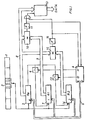
Aus dem Sub-Codewort 1 wird ein interessierendes auszuwertendes Codeelement 2 herausgegriffen. Die Daten-BITS dieses ausgewählten Codeelements werden in ein erstes Register 3 (Ra) eingelesen. Eine Steuerschaltung 4 aktiviert über eine Datenleitung 5 dieses Register. Der Ausgang A der Steuerschaltung 4 schaltet ein Tor 6 durchlässig, so dass die Daten in das über die Leitung 5 aktivierte Register 7 (R1) gelangen. (Erste Einleseperiode.) Daraufhin werden neue Daten in das erste Register 3 (Ro) geschrieben. (Zweite Einleseperiode.) Die Steuerschaltung 4 bringt die in den beiden Registern 3 (Ro) und 7 (R1) gespeicherten Daten über die Datenleitung 8 und 9 an eine Vergleichsstufe 10. Bei positivem Ergebnis, d.h. bei Gleichheit, gibt die Fehlererkennungsschaltung 11 ein Signal an die Stufe 12 ab, welche die Daten aus dem Register 3 zur Auswertung durchschaltet. Fällt der Vergleich negativ aus, sperrt die Fehler-Erkennungsschaltung 11 die Stufe 12 und gibt an die Steuerschaltung 4 gleichzeitig ein Signal, wonach die Steuerschaltung 4 über ihren Ausgang B das Tor 13 öffnet, wonach die in dem ersten Register 3 (Ro) eingelesenen Daten in das von der Steuerschaltung 4 über die Leitung 5 aktivierte Register 14 (R2) gelangen. Die eingelesenen aktuellen neuen Daten im Register 3 (Ro) werden mit den zuletzt eingelesenen im Register 14 (R2) abgelegten Daten in der Vergleichsstufe 15 verglichen. Falls der Vergleich negativ ausfällt, gelangt über die Fehlererkennungsschaltung 16 ein Signal an die Steuerschaltung 4. Hierdurch wird ein Vergleich des Inhalts des Registers 3 (Ro) aus der dritten Einleseperiode mit dem Inhalt des Registers 7 (R1) aus der ersten Einleseperiode vorgenommen. Der Vergleich findet über die Vergleichsstufe 10 statt. Bei positivem Ergebnis wird über die Fehlererkennungsschaltung 11 die Stufe 12 zur Durchschaltung der Daten freigegeben. Bei negativem Ergebnis erzeugt die Fehlererkennungsschaltung 11 ein Signal für die Steuerschaltung 4, die das Register 7 (R1) freigibt, so dass über das geöffnete Tor 6 die aktuellen Daten der dritten Einleseperiode aus dem Register 3 (Ro) eingeschrieben werden, die für einen nachfolgenden Vergleich aus der vierten Einleseperiode in der Vergleichsstufe 10 zur Verfügung stehen.An
Nach vorbeschriebener Weise können sämtliche einzelnen Codeelemente eines Q-Blocks getrennt überprüft werden, indem ein entsprechendes Fenster zur Selektierung eines bestimmten Codeelements gesetzt wird.In the manner described above, all individual code elements of a Q block can be checked separately by setting a corresponding window for selecting a specific code element.
Der mit Hilfe der Fig. 1 beschriebene Aufwand kann durch eine geeignete Zusammenfassung der Vergleichsstufen 10 und 15 sowie der Fehlererkennungsschaltung 11 und 16 zu jeweils einer einzigen von der Steuerschaltung 4 gesteuerten Schaltung reduziert werden.The effort described with the aid of FIG. 1 can be reduced by a suitable combination of the
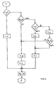
In Fig. 2 ist das soeben beschriebene Verfahren in Form eines Flussdiagramms aufgezeichnet. Die zu prüfenden Daten aus dem selektierten Codeelement des Blocks gelangen über A an eine Abfrage eines Einleseperiodenzählers, welcher die Anzahl der eingelesenen Codeelemente zählt. Nach Einschalten des Gerätes, z. B. des Compact-Disc-Gerätes, steht dieser Zähler auf Null. Danach wird der Zähler auf n = 1 gesetzt. Die eingelesenen Daten werden vom Einlaufregister Ro in das erste Register R1 überschrieben.2, the method just described is recorded in the form of a flow chart. The data to be checked from the selected code element of the block is sent via A to a query of a read-in period counter, which counts the number of code elements read. After switching on the device, e.g. B. the compact disc device, this counter is at zero. Then the counter is set to n = 1. The read data are overwritten by the entry register R o in the first register R 1 .
Es findet nun der erste Vergleich statt, indem der Inhalt des zweiten Dateneinlaufs, der sich nun im Einlaufregister Ro befindet, mit den im Register R1 gespeicherten Daten aus der ersten Dateneinleseperiode verglichen wird. Bei positivem Ergebnis wird eine Marke F = gesetzt, d.h., dass die Daten im Register 1 gültig, d.h. richtig sind. Der Zähler wird auf n = 1 gesetzt und der Inhalt des Registers Ro in das Register R1 überschrieben.The first comparison now takes place in that the content of the second data entry, which is now located in the entry register R o, is compared with the data from the first data reading period stored in the register R 1 . If the result is positive, a flag F = is set, which means that the data in
Falls der Vergleich negativ ausfällt, wird in einer weiteren Stufe der Zählerstand nach n = 2? abgefragt. Da bis dahin der Zähler auf n = 1 stand, wird nun dieser auf n = 2 gesetzt, wodurch der im Register Ro befindliche Inhalt aus der zweiten Einleseperiode in das Register R2 überschrieben wird. Die Marke wird auf 1 gesetzt zur Anzeige, dass die Daten ungültig, d.h. falsch, sind.If the comparison turns out to be negative, the meter reading is changed to n = 2? queried. Since the counter had previously been at n = 1, it is now set to n = 2, as a result of which the content in the register R o from the second reading period is overwritten in the register R 2 . The flag is set to 1 to indicate that the data is invalid.
Nun gelangt der dritte Dateneinlauf über A an die Abfrage n = 0? Da der Zähler aber auf n = 2 steht wird der Inhalt aus der dritten Einleseperiode des Registers Ro mit dem Inhalt des Registers R2 aus der vorhergehenden zweiten Einleseperiode verglichen. Bei positivem Ergebnis wird die Marke F = 0 gesetzt zur Anzeige, dass die Daten gültig, d. h. richtig, sind. Der Zähler wird daraufhin auf n = 1 gesetzt, wonach die Daten aus dem Register Ro in das Register R1 überschrieben werden, um für den nächsten Dateneinlauf der vierten Einleseperiode zur Verfügung zu stehen.Now the third data entry via A reaches the query n = 0? However, since the counter is at n = 2, the content from the third read-in period of the register R o is compared with the content of the register R 2 from the previous second read-in period. If the result is positive, the flag F = 0 is set to indicate that the data are valid, ie correct. The counter is then set to n = 1, after which the data from the register R o are overwritten in the register R 1 in order to be available for the next data entry of the fourth read-in period.
Bei negativem Entscheid wird der Zählerstand nach n = 2? abgefragt, worauf dieser auf n = 1 zurückgesetzt wird. Die aus der dritten Einleseperiode in Ro befindlichen Daten werden nun mit denjenigen im Register R1 befindlichen verglichen. Bei positivem Ergebnis wird wieder die Marke F = 0 gesetzt. Bei negativem Ergebnis dagegen wird die Ungültigkeit der Daten mit F = 1 angezeigt und die Daten aus der dritten Einleseperiode aus dem Register Ro in das Register R1 geschoben. Dadurch stehen diese Daten aus der dritten Einleseperiode für den nachfolgenden Datenvergleich nach der vierten Einleseperiode als Referenz zur Verfügung.If the decision is negative, the counter reading is changed to n = 2? queried, whereupon this is reset to n = 1. The data in R o from the third read-in period are now compared with those in register R 1 . If the result is positive, the F = 0 mark is set again. If the result is negative, on the other hand, the invalidity of the data is indicated with F = 1 and the data from the third read-in period are shifted from the register R o into the register R 1 . As a result, this data from the third read-in period is available as a reference for the subsequent data comparison after the fourth read-in period.
Das mit Hilfe der Fig. 1 beschriebene Verfahren bezieht sich auf einen Dreier-Vergleich von nacheinander eingelesenen Daten eines Codeelements. Bei weniger hohen Genauigkeitsanforderungen kann auch ein Zweier-Vergleich von Daten zweier aufeinander folgender Codeelemente vorgenommen werden, wodurch der Aufwand zur Durchführung des Verfahrens um einiges reduziert werden kann.The method described with the aid of FIG. 1 relates to a three-way comparison of data of a code element read in one after the other. If the accuracy requirements are not so high, a two-way comparison of data from two successive code elements can also be carried out, as a result of which the effort for implementing the method can be reduced considerably.
Claims (1)
Applications Claiming Priority (2)
| Application Number | Priority Date | Filing Date | Title |
|---|---|---|---|
| DE3336747 | 1983-10-08 | ||
| DE3336747A DE3336747C2 (en) | 1983-10-08 | 1983-10-08 | Method for evaluating a control code word consisting of several code elements |
Publications (2)
| Publication Number | Publication Date |
|---|---|
| EP0137425A1 EP0137425A1 (en) | 1985-04-17 |
| EP0137425B1 true EP0137425B1 (en) | 1988-12-07 |
Family
ID=6211410
Family Applications (1)
| Application Number | Title | Priority Date | Filing Date |
|---|---|---|---|
| EP84111588A Expired EP0137425B1 (en) | 1983-10-08 | 1984-09-28 | Method for detecting a subcode |
Country Status (8)
| Country | Link |
|---|---|
| US (1) | US4852105A (en) |
| EP (1) | EP0137425B1 (en) |
| JP (1) | JPS61500390A (en) |
| DE (2) | DE3336747C2 (en) |
| DK (1) | DK257185A (en) |
| HK (1) | HK140893A (en) |
| IE (1) | IE55776B1 (en) |
| WO (1) | WO1985001824A1 (en) |
Families Citing this family (18)
| Publication number | Priority date | Publication date | Assignee | Title |
|---|---|---|---|---|
| DE3704898A1 (en) * | 1986-02-20 | 1987-08-27 | Sharp Kk | DISKETTE RECORDING PROCEDURE |
| JPS63127469A (en) * | 1986-11-18 | 1988-05-31 | Sony Corp | Recording and reproducing device for recordable optical disk |
| DE3801123A1 (en) * | 1988-01-16 | 1989-07-27 | Philips Patentverwaltung | MEDIATION SYSTEM |
| EP0325325B1 (en) * | 1988-01-19 | 1996-09-04 | Koninklijke Philips Electronics N.V. | System for transferring information using an information carrier |
| JPH07118798B2 (en) * | 1988-02-29 | 1995-12-18 | パイオニア株式会社 | Image information recording and reproducing method |
| JP2938077B2 (en) * | 1988-03-11 | 1999-08-23 | パイオニア株式会社 | Image signal recording method and image reproduction method |
| JP2778169B2 (en) * | 1989-12-30 | 1998-07-23 | ソニー株式会社 | Digital signal processing circuit |
| JP2803351B2 (en) * | 1990-09-14 | 1998-09-24 | 日本電気株式会社 | Majority circuit |
| WO1992012481A1 (en) * | 1990-12-27 | 1992-07-23 | Motorola, Inc. | Wireless personal communication system |
| DE4133965A1 (en) * | 1991-10-14 | 1993-04-15 | Standard Elektrik Lorenz Ag | Abstractor for identification of data sequence - has data processed by evaluator stage coupled to decision making stage to identify original form |
| WO1993026104A1 (en) * | 1992-06-05 | 1993-12-23 | Smart Tag Systems, Inc. | Device and method for detection of intermittently repeating information |
| US5592404A (en) * | 1993-11-04 | 1997-01-07 | Cirrus Logic, Inc. | Versatile error correction system |
| GB2333886B (en) * | 1995-06-23 | 2000-01-12 | Sony Corp | Device for reproducing a recording medium having plural recording areas |
| JP3521552B2 (en) * | 1995-06-23 | 2004-04-19 | ソニー株式会社 | Playback device |
| US5691723A (en) * | 1995-09-11 | 1997-11-25 | E-Systems, Inc. | Apparatus and method for encoding and decoding data on tactical air navigation and distance measuring equipment signals |
| US5870406A (en) * | 1997-02-19 | 1999-02-09 | Ericsson Inc. | Automatic repeat request(ARQ) data communications method and apparatus |
| JP3534629B2 (en) * | 1998-12-10 | 2004-06-07 | 株式会社三協精機製作所 | Demodulation method of magnetic recording data |
| US9715420B2 (en) * | 2015-01-21 | 2017-07-25 | International Business Machines Corporation | String dataflow error detection |
Citations (1)
| Publication number | Priority date | Publication date | Assignee | Title |
|---|---|---|---|---|
| DE3130145A1 (en) * | 1980-07-31 | 1982-03-11 | Hitachi, Ltd., Tokyo | INTERFACE CONTROL SYSTEM |
Family Cites Families (11)
| Publication number | Priority date | Publication date | Assignee | Title |
|---|---|---|---|---|
| GB1575002A (en) * | 1976-03-11 | 1980-09-17 | Post Office | Data transmission system |
| FR2435776A1 (en) * | 1978-09-08 | 1980-04-04 | Charbonnages De France | Recording and reading signals on magnetic tape cassette - allows microprocessor to format signals for controlling power circuits and drive circuits in larger system |
| IT1121390B (en) * | 1979-06-12 | 1986-04-02 | Telettra Lab Telefon | UNIVERSAL FRAME FOR HOUSING OF TELECOMMUNICATIONS EQUIPMENT |
| FR2458874A1 (en) * | 1979-06-13 | 1981-01-02 | France Etat | Footage recording on video tape - uses microprocessor to detect and process time data recorded on synchronising track |
| US4375101A (en) * | 1980-09-30 | 1983-02-22 | Video Education, Inc. | System for formatting data on video tape for high accuracy recovery |
| JPS57198586A (en) * | 1981-05-28 | 1982-12-06 | Sony Corp | Digital disc reproducing device |
| JPS5848279A (en) * | 1981-09-14 | 1983-03-22 | Sony Corp | Cue signal processor |
| US4518947A (en) * | 1981-09-28 | 1985-05-21 | E-Systems, Inc. | Apparatus for decoding redundant interleaved data |
| JPS58133689A (en) * | 1982-02-02 | 1983-08-09 | Sony Corp | Digital audio disc device |
| NL8200560A (en) * | 1982-02-15 | 1983-09-01 | Philips Nv | SYSTEM FOR COMMUNICATION BY RE-MESSAGES TRANSMITTED MESSAGES AND STATIONS FOR USE IN SUCH A SYSTEM. |
| US4577332A (en) * | 1983-03-14 | 1986-03-18 | General Electric Company | Digital decoding arrangement |
-
1983
- 1983-10-08 DE DE3336747A patent/DE3336747C2/en not_active Expired
-
1984
- 1984-09-28 WO PCT/EP1984/000296 patent/WO1985001824A1/en unknown
- 1984-09-28 DE DE8484111588T patent/DE3475582D1/en not_active Expired
- 1984-09-28 JP JP59503661A patent/JPS61500390A/en active Pending
- 1984-09-28 EP EP84111588A patent/EP0137425B1/en not_active Expired
- 1984-10-05 IE IE2562/84A patent/IE55776B1/en not_active IP Right Cessation
-
1985
- 1985-06-07 US US06/742,619 patent/US4852105A/en not_active Expired - Lifetime
- 1985-06-07 DK DK257185A patent/DK257185A/en not_active Application Discontinuation
-
1993
- 1993-12-23 HK HK1408/93A patent/HK140893A/en not_active IP Right Cessation
Patent Citations (1)
| Publication number | Priority date | Publication date | Assignee | Title |
|---|---|---|---|---|
| DE3130145A1 (en) * | 1980-07-31 | 1982-03-11 | Hitachi, Ltd., Tokyo | INTERFACE CONTROL SYSTEM |
Non-Patent Citations (1)
| Title |
|---|
| Lesea/Zaks: Mikroprozessor Interface Techniken, 4. Aufl. 1982, pp. 328-332 * |
Also Published As
| Publication number | Publication date |
|---|---|
| DK257185D0 (en) | 1985-06-07 |
| DE3336747C2 (en) | 1985-11-28 |
| IE55776B1 (en) | 1991-01-16 |
| DE3475582D1 (en) | 1989-01-12 |
| DE3336747A1 (en) | 1985-05-02 |
| JPS61500390A (en) | 1986-03-06 |
| DK257185A (en) | 1985-06-07 |
| EP0137425A1 (en) | 1985-04-17 |
| HK140893A (en) | 1993-12-31 |
| WO1985001824A1 (en) | 1985-04-25 |
| IE842562L (en) | 1985-04-08 |
| US4852105A (en) | 1989-07-25 |
Similar Documents
| Publication | Publication Date | Title |
|---|---|---|
| EP0137425B1 (en) | Method for detecting a subcode | |
| DE3704898C2 (en) | ||
| DE19638161B4 (en) | Recording method for an optical disk drive apparatus | |
| DE3131413A1 (en) | METHOD AND DEVICE FOR DETECTING AN EDING POINT ON A RECORDING MEDIUM | |
| DE1295246B (en) | Circuit arrangement for error-proof reproduction of digital signals displayed in parallel | |
| EP0717407B1 (en) | Vibration-resistant reproducing apparatus with improved synchronisation | |
| DE2944177A1 (en) | INFORMATION SYSTEM ON ALL FUNCTIONS OF A MUSIC MACHINE | |
| KR870008287A (en) | Digital information storage and reading method and apparatus therefor | |
| DE3238077A1 (en) | METHOD AND CIRCUIT ARRANGEMENTS FOR DETECTING AND EVALUATING DEFECTS ON RECORDING CARRIERS WITH DIGITAL SIGNALS RECORDED IN AT LEAST ONE TRACK | |
| EP0144831B1 (en) | Apparatus arrangement for the determination of errors on disk-shaped record carriers | |
| DE3820590C2 (en) | Method for determining empty areas on a record carrier | |
| DE3045609A1 (en) | METHOD AND CIRCUIT FOR DELIVERING A CORRECTED DATA GROUP TO A DETERMINATION CIRCUIT | |
| DE4204122C2 (en) | Method for preventing erroneous recording in a CD device | |
| EP0037487B1 (en) | Method and apparatus for retrieving a storage position on a record carrier | |
| DE2921544C2 (en) | Control circuit for writing and reading data records for memory devices with circulating data memories | |
| DE60106476T2 (en) | METHOD AND DEVICE FOR DETERMINING THE MAIN PARAMETER VALUES OF A STORAGE MEDIUM REQUIRED FOR PLAYING THE STORAGE MEDIUM | |
| DE2853449A1 (en) | PROCEDURE FOR FAULT LOCATION IN A LARGE STORAGE SYSTEM | |
| DE3401421A1 (en) | ADDRESS DATA TRANSFER DEVICE | |
| DE19850020A1 (en) | Device for playing back information stored digitally on an optical information disc | |
| DE3341363A1 (en) | Method of identifying individual files recorded on a recording carrier in tape form | |
| DE3705185C2 (en) | ||
| WO1992022064A1 (en) | Signalization of types of defects of an optical information carrier | |
| DE2851822A1 (en) | Fault detector for information storage discs - detects faults due to scratches on spiral track of rotating disc, by using shift registers and logic gates | |
| JPS60120680A (en) | System of data processing | |
| SU1173444A2 (en) | Device for error correction in digital magnetic storage |
Legal Events
| Date | Code | Title | Description |
|---|---|---|---|
| PUAI | Public reference made under article 153(3) epc to a published international application that has entered the european phase |
Free format text: ORIGINAL CODE: 0009012 |
|
| AK | Designated contracting states |
Designated state(s): BE CH DE FR GB IT LI LU NL SE |
|
| 17P | Request for examination filed |
Effective date: 19850919 |
|
| 17Q | First examination report despatched |
Effective date: 19861118 |
|
| ITF | It: translation for a ep patent filed |
Owner name: ING. ZINI MARANESI & C. S.R.L. |
|
| GRAA | (expected) grant |
Free format text: ORIGINAL CODE: 0009210 |
|
| AK | Designated contracting states |
Kind code of ref document: B1 Designated state(s): BE CH DE FR GB IT LI LU NL SE |
|
| GBT | Gb: translation of ep patent filed (gb section 77(6)(a)/1977) | ||
| REF | Corresponds to: |
Ref document number: 3475582 Country of ref document: DE Date of ref document: 19890112 |
|
| ET | Fr: translation filed | ||
| PLBE | No opposition filed within time limit |
Free format text: ORIGINAL CODE: 0009261 |
|
| STAA | Information on the status of an ep patent application or granted ep patent |
Free format text: STATUS: NO OPPOSITION FILED WITHIN TIME LIMIT |
|
| 26N | No opposition filed | ||
| ITTA | It: last paid annual fee | ||
| PGFP | Annual fee paid to national office [announced via postgrant information from national office to epo] |
Ref country code: LU Payment date: 19920820 Year of fee payment: 9 |
|
| PGFP | Annual fee paid to national office [announced via postgrant information from national office to epo] |
Ref country code: BE Payment date: 19920909 Year of fee payment: 9 |
|
| PGFP | Annual fee paid to national office [announced via postgrant information from national office to epo] |
Ref country code: SE Payment date: 19920917 Year of fee payment: 9 |
|
| PGFP | Annual fee paid to national office [announced via postgrant information from national office to epo] |
Ref country code: CH Payment date: 19920929 Year of fee payment: 9 |
|
| PGFP | Annual fee paid to national office [announced via postgrant information from national office to epo] |
Ref country code: NL Payment date: 19920930 Year of fee payment: 9 |
|
| EPTA | Lu: last paid annual fee | ||
| PG25 | Lapsed in a contracting state [announced via postgrant information from national office to epo] |
Ref country code: LU Free format text: LAPSE BECAUSE OF NON-PAYMENT OF DUE FEES Effective date: 19930928 |
|
| PG25 | Lapsed in a contracting state [announced via postgrant information from national office to epo] |
Ref country code: SE Effective date: 19930929 |
|
| PG25 | Lapsed in a contracting state [announced via postgrant information from national office to epo] |
Ref country code: LI Effective date: 19930930 Ref country code: CH Effective date: 19930930 Ref country code: BE Effective date: 19930930 |
|
| BERE | Be: lapsed |
Owner name: DEUTSCHE THOMSON-BRANDT G.M.B.H. Effective date: 19930930 |
|
| PG25 | Lapsed in a contracting state [announced via postgrant information from national office to epo] |
Ref country code: NL Effective date: 19940401 |
|
| NLV4 | Nl: lapsed or anulled due to non-payment of the annual fee | ||
| REG | Reference to a national code |
Ref country code: CH Ref legal event code: PL |
|
| EUG | Se: european patent has lapsed |
Ref document number: 84111588.4 Effective date: 19940410 |
|
| REG | Reference to a national code |
Ref country code: GB Ref legal event code: 746 Effective date: 19970822 |
|
| REG | Reference to a national code |
Ref country code: FR Ref legal event code: D6 |
|
| REG | Reference to a national code |
Ref country code: GB Ref legal event code: IF02 |
|
| PGFP | Annual fee paid to national office [announced via postgrant information from national office to epo] |
Ref country code: GB Payment date: 20030710 Year of fee payment: 20 |
|
| PGFP | Annual fee paid to national office [announced via postgrant information from national office to epo] |
Ref country code: DE Payment date: 20030909 Year of fee payment: 20 |
|
| PGFP | Annual fee paid to national office [announced via postgrant information from national office to epo] |
Ref country code: FR Payment date: 20030911 Year of fee payment: 20 |
|
| PG25 | Lapsed in a contracting state [announced via postgrant information from national office to epo] |
Ref country code: GB Free format text: LAPSE BECAUSE OF EXPIRATION OF PROTECTION Effective date: 20040927 |
|
| REG | Reference to a national code |
Ref country code: GB Ref legal event code: PE20 |