EP0136705B1 - Engrenage - Google Patents
Engrenage Download PDFInfo
- Publication number
- EP0136705B1 EP0136705B1 EP19840111812 EP84111812A EP0136705B1 EP 0136705 B1 EP0136705 B1 EP 0136705B1 EP 19840111812 EP19840111812 EP 19840111812 EP 84111812 A EP84111812 A EP 84111812A EP 0136705 B1 EP0136705 B1 EP 0136705B1
- Authority
- EP
- European Patent Office
- Prior art keywords
- gear
- wheel
- cable
- freewheels
- freewheel
- Prior art date
- Legal status (The legal status is an assumption and is not a legal conclusion. Google has not performed a legal analysis and makes no representation as to the accuracy of the status listed.)
- Expired - Lifetime
Links
Images


Classifications
-
- A—HUMAN NECESSITIES
- A61—MEDICAL OR VETERINARY SCIENCE; HYGIENE
- A61G—TRANSPORT, PERSONAL CONVEYANCES, OR ACCOMMODATION SPECIALLY ADAPTED FOR PATIENTS OR DISABLED PERSONS; OPERATING TABLES OR CHAIRS; CHAIRS FOR DENTISTRY; FUNERAL DEVICES
- A61G5/00—Chairs or personal conveyances specially adapted for patients or disabled persons, e.g. wheelchairs
- A61G5/02—Chairs or personal conveyances specially adapted for patients or disabled persons, e.g. wheelchairs propelled by the patient or disabled person
- A61G5/021—Chairs or personal conveyances specially adapted for patients or disabled persons, e.g. wheelchairs propelled by the patient or disabled person having particular propulsion mechanisms
- A61G5/023—Chairs or personal conveyances specially adapted for patients or disabled persons, e.g. wheelchairs propelled by the patient or disabled person having particular propulsion mechanisms acting directly on hubs or axis
-
- A—HUMAN NECESSITIES
- A61—MEDICAL OR VETERINARY SCIENCE; HYGIENE
- A61G—TRANSPORT, PERSONAL CONVEYANCES, OR ACCOMMODATION SPECIALLY ADAPTED FOR PATIENTS OR DISABLED PERSONS; OPERATING TABLES OR CHAIRS; CHAIRS FOR DENTISTRY; FUNERAL DEVICES
- A61G5/00—Chairs or personal conveyances specially adapted for patients or disabled persons, e.g. wheelchairs
- A61G5/02—Chairs or personal conveyances specially adapted for patients or disabled persons, e.g. wheelchairs propelled by the patient or disabled person
- A61G5/024—Chairs or personal conveyances specially adapted for patients or disabled persons, e.g. wheelchairs propelled by the patient or disabled person having particular operating means
- A61G5/025—Levers
-
- B—PERFORMING OPERATIONS; TRANSPORTING
- B62—LAND VEHICLES FOR TRAVELLING OTHERWISE THAN ON RAILS
- B62M—RIDER PROPULSION OF WHEELED VEHICLES OR SLEDGES; POWERED PROPULSION OF SLEDGES OR SINGLE-TRACK CYCLES; TRANSMISSIONS SPECIALLY ADAPTED FOR SUCH VEHICLES
- B62M1/00—Rider propulsion of wheeled vehicles
- B62M1/14—Rider propulsion of wheeled vehicles operated exclusively by hand power
Definitions
- the invention relates to a transmission for muscle-powered vehicles or devices according to the preamble of the main claim.
- EP-OS-0 0 040 205 and US-PS-3 301 574 gearboxes with reverse gear are known, which work with reversible directional locks.
- these gears have the disadvantage that they use only one of the two drive movements for the rotary movement of the drive and each accept an idle stroke.
- the invention has for its object to provide a transmission of the type mentioned, which is small and light, in which both lifting movements of a hand lever can be used for the forward movement, without having to bridge an idle and which alternatively enables a reverse gear movement using at least one of the two strokes of the hand lever.
- At least one further, third freewheel is thus arranged, which has an opposite direction of rotation. All freewheels do not act directly on the drive shaft, but the two first and second freewheels of the same direction of rotation act on an inner ring intended for the forward gear and the opposite third freewheel acts on an inner ring designed as a reverse sleeve for the reverse gear. Both inner rings can optionally be coupled to a hollow shaft as the drive shaft by means of gear teeth or remain uncoupled from the hollow shaft when idling.
- all freewheels ie both the freewheels for the forward movement and the freewheel for the reverse gear, are in motion when the actuating lever is pivoted, that is to say that the freewheels are not selectively put into operation, but are in a constant rotational movement.
- the choice between the forward movement and the reverse gear is made in that the clutch device is actuated, which is further designed so that an idling is also possible, in which, for example, the wheelchair can be freely moved.
- all Freewheels at the same time that is to say simultaneously driven or set in rotation, while the clutch device determines which of the freewheels is in drive connection.
- the choice of the direction of movement is thus made by actuating the coupling device. This makes it possible to design the transmission according to the invention to be particularly small and space-saving, since in each case only the power transmission line has to be set up by the coupling device, but not complicated switching processes or the like, for example using gearwheels, are required.
- the principle according to the invention thus makes it possible to use both the forward and the return stroke of the actuating lever for the forward movement. Since the vehicle is usually not driven at all or not as quickly in reverse, it is sufficient to use only one of the two strokes in reverse. By simply expanding the transmission with a second reverse gear freewheel, however, a reverse drive device corresponding to the forward movement can also be realized without the basic construction of the transmission having to be changed thereby.
- the drive lever of the transmission is further preferred to connect the drive lever of the transmission to the freewheels via an open and a crossed cable drive in order to always drive them in opposite directions.
- the drive lever can be used by moving it towards its pivot point for brake actuation and by turning it about its longitudinal axis for steering. It is also ensured by a connection of the shift rod and the handlebar that the forced steering is effective in forward and reverse gear and the self-steering of the muscle-powered vehicle in idle.
- a transmission 10 is rotatably mounted on a thru axle 11 of a vehicle, for example a wheelchair, by means of roller bearings 13, 14 on a hollow shaft 12.
- a wheel hub 15 On this hollow shaft 12 is a wheel hub 15 by screws 16 or the like. attached, with the spokes (not shown) for a wheel rim 17 of a muscle-powered vehicle, such as a wheelchair or the like, attached to the wheel hub 15 in a conventional manner.
- the wheel hub 15 represents the output member of the transmission 10 described here.
- a first is located within the wheel hub 15 Freewheel 18, which is driven by a wheel, for example a rope wheel 19.
- a second freewheel 20 is arranged, which is driven by a second cable wheel 21.
- the freewheels 18, 20 are mounted to act with the same direction of rotation, while the two rope wheels 19, 21 are driven in opposite oscillating fashion and are provided for the forward movement of the wheel hub 15.
- switchable idling is achieved in that the two freewheels 18, 20 do not act directly on the shaft 12, but on an inner ring 22 which is designed as a forward sleeve.
- the forward sleeve 22 can rotate on the shaft 12 without taking it along. It is therefore in the idle position.
- Coupling elements are used for driving the hollow shaft 12 through the forward sleeve 22, e.g. the inner toothing 23 of the forward sleeve 22, which engages in an outer toothing 24 of the shaft 12 when the forward sleeve 22 is shifted to the right.
- the rotation of the shift sleeve 25 can be effected by the shift rod 30.
- the retaining ring 35 which is firmly pressed into the rear sleeve 32, in cooperation with a flange ring 36, which is firmly pressed into the forward sleeve 22 (inner ring), ensures that the rear sleeve 32 participates in the axial displacement of the forward sleeve 22, but can rotate independently of it.
- the reverse sleeve 32 comes somewhat into the "wrong" freewheel 20. This is remedied by a chamfer 37 of the reverse sleeve 32.
- a chamfer 38 of the forward sleeve 22 The same applies to a chamfer 38 of the forward sleeve 22.
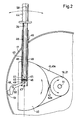
- the reverse gear which is provided by the freewheel 31, is only single-acting, which is only effective in the pulling or pushing stroke of a drive lever 39, see FIG. 2. This is sufficient in view of the less frequent use of reverse gear.
- a double-acting reverse gear a further, fourth freewheel had to be inserted into the rope wheel 19.
- the double-acting forward gear, the single-acting reverse gear and the idling speed, including the shift mechanism, are accommodated in the wheel hub 15 in very small dimensions and thus in a weight-saving manner.
- the width of the gear 10 resulting essentially from the width of the three freewheels 18, 20, 31 leads to a flange distance of the wheel hub 15 which corresponds to that of conventional wheel rims 17 of muscle-struck vehicles.
- the rope wheels 19, 21 must always be driven oscillating in opposite directions. If they ended up in gears, they could be driven with a double rack. If they ended up in levers, they could be driven with one push rod each. Gear, chain or belt drives are also possible. Cable drives, as shown in Fig. 2, are even lighter, more space-saving and less expensive. While the one rope wheel 19 is connected as a belt drive to a larger pitch circle wheel 40, the rope wheel 21 lying in front acts with a crossed belt drive on the larger pitch circle wheel 40. As a result, the cable wheels 19, 21 always rotate in opposite directions to one another with each reciprocating movement of the larger pitch circle wheel 40. The for the respective application, e.g.
- a tubular drive sleeve 43 in which a drive lever 39 with a handle 44 can be pulled out, is fastened to the larger pitch circle wheel 40.
- Suspended balls 45 in the drive lever 39 can, in conjunction with holes 46 in the drive sleeve 35, ensure a certain lever length and, as it were, mark the 1st, 2nd and 3rd gear. Assuming constant arc length and operating frequency on the drive lever 39, this change in the lever length represents a real gearshift, namely with longer lever a greater torque at lower speed.
- the center of rotation 47 of the pitch circle wheel 40 is in the vicinity of the wheel rim 17, which is connected to the wheel hub 15 by spokes and thus rotates around the thru axle 11. This fact is used in the further embodiment of the transmission in order to actuate a brake with the handle 44, which is independent of the angular position of the pitch wheel 40 and its drive lever 39.
- the tip of the brake lever 48 is in the vicinity of the pivot point 47 of the pitch wheel 40 and can be rotated about the axis 50 by moving the drive lever 39 with its end face 49 so that the brake pad by pressing down the handle 44 with more or less force can be pressed against the wheel rim 17.
- an axial pressure on the wheel rim 17 can also be achieved with greater effort.
- a further perfection of the transmission relates to the actuation of the shift sleeve 25 by the shift rod 30. Since in the construction shown in FIG. 1 there are no synchronization means for the toothings 23, 24 and 33, 34, their front sides can collide when shifting, so that none Intervention takes place. With a slow relative movement of the toothing, it would have to be switched with feeling to let the teeth get into the tooth gaps.
- FIGS. 3 and 5 It is more advantageous to preselect the gears using a toggle switch, which is shown in FIGS. 3 and 5.
- the switching sleeve 25 is in the idle position.
- the shift rod 30 is equipped with a ball handle 52 for easy actuation.
- a rocker arm 54 and a compression spring 55 are mounted in a joint 53 on the shift rod 30, which in turn is supported on the fixed pivot point 56. Since the lines of action of the rocker arm 54 and the compression spring 55 are aligned in FIG. 3, the system is in metastable equilibrium. After gently pulling the ball handle 52 to the left, see Fig. 5, the compression spring 55 presses further to the left and pulls the rocker arm 54, the shift rod 30 and the shift sleeve 25 with it.
- the idle position outlined in FIG. 3 serves for this wheelchair can be driven as usual by means of its push rims, because the transmission 10 is switched off due to a lack of tooth engagement.
- the drive lever 39 can be pivoted into a position that does not disturb the push rim actuation. Driving with push rims is particularly suitable for driving in rooms and confined spaces.
- the wheelchair's steering wheels can turn automatically by 360 °.
- the wheelchair drive via hand lever is much more suitable for driving outdoors. Steering can be problematic on routes that are inclined at right angles to the direction of travel.
- the steering wheels which are then set downward, are advantageously positively steered via the drive sleeve 43, which is fastened to the larger pitch wheel 40 about the longitudinal axis 58, see FIG. 2.
- the steering wheel fork 63 is rotated about its axis of rotation 64 via a ball joint 60 and a steering rod 61 by means of its bolts 62, namely by turning the handle 44
- the type of steering is only desirable when the forward or reverse gear is engaged.
- the handlebar 61 can be separated from the steering wheel fork 63, see Fig.3, namely caused by a cable-like mechanical connection 65 between the handlebar 61 and the shift rod 30, in that the rocker arm 54 brings the shift rod 30 into a higher position when idle , whereby the handlebar 61 is also raised so that its pin 62 separates from the hole 66 of the steering wheel fork 63.
- the shift rod 30 and with it the handlebar 61 lowers so that their pin 62 can dip into the hole 66 of the steering wheel fork 63.
- the steering wheel fork 63 may have rotated about its axis of rotation 64, so that the bolt 62 plunges into space.
Landscapes
- Engineering & Computer Science (AREA)
- Life Sciences & Earth Sciences (AREA)
- Animal Behavior & Ethology (AREA)
- General Health & Medical Sciences (AREA)
- Public Health (AREA)
- Veterinary Medicine (AREA)
- Health & Medical Sciences (AREA)
- Chemical & Material Sciences (AREA)
- Combustion & Propulsion (AREA)
- Transportation (AREA)
- Mechanical Engineering (AREA)
- Structure Of Transmissions (AREA)
- Gear-Shifting Mechanisms (AREA)
Claims (11)
- Engrenage pour véhicules ou appareils à commande musculaire, destiné à transformer un mouvement en va-et-vient en une rotation de sens constant avec deux roues libres (18, 20) entraînées en alternance en sens contraire et agissant dans le même sens sur un arbre (12), caractérisé en ce qu'une troisième roue libre (31) au moins qui est conçue de manière à agir dans le sens contraire aux deux premières roues libres, est entraînée en même temps que les deux premières roues libres (18, 20) et en ce qu au moyen d'un dispositif d'accouplement (23, 24, 33, 34) les roues libres (18, 20), de même sens pour la marche avant ou la troisième roue libre (31) de sens contraire pour la marche arrière, peuvent être amenées en prise active avec l'arbre (12), en marche à vide, aucune des trois roues libres (18, 20, 31) n'est en prise avec l'arbre (2).
- Engrenage selon la revendication 1, caractérisé en ce que sur l'arbre (12), la troisième roue libre (31) pour la marche arrière est en liaison avec les roues libres (18, 20) entraînées en sens contraire, par l'intermédiaire d'une denture (33, 34) et cette denture (33, 34) de la troisième roue libre (31) ainsi que les dentures (23, 24) des deux premières roues libres (18, 20) peuvent être commandées par l'intermédiaire d'un manchon de manoeuvre (25), au moyen d'une tringle de manoeuvre (30).
- Engrenage selon la revendication 1 ou 2, caractérisé en ce que les deux premières roues libres (18, 20) sont montées sur une bague intérieure (22) et peuvent être entraînées en sens contraire, par l'intermédiaire d'une première poulie à câble (19) et d'une deuxième poulie à câble (21), au moyen d'un premier câble (41, 41a) ou d'un deuxième câble (42, 42a) lesquels sont reliés au moyen d'une roue à cercle primitif (40) et en ce qu'à la bague intérieure (22) est associé, axialement par rapport à l'arbre (12), un manchon arrière (32).
- Engrenage selon la revendication 3, caractérisé en ce que le manchon arrière (32) placé dans la troisième roue libre (31) est muni de dentures intérieures (33) qui peuvent être amenées en prise avec les dentures extérieures (34) de l'arbre (12) pour l'entraînement d'un moyeu de roue (15) et qui peuvent être entraînées par la deuxième poulie à câble (21).
- Engrenage selon la revendication 3 ou 4, caractérisé en ce que la bague intérieure (22) présente une denture intérieure (23) qui peut être reliée à une denture extérieure (24) de l'arbre (12) pour l'entraînement du moyeu de roue (15) pour la marche avant, et en ce que la marche à vide est rendue possible par le désengrènement de toutes les dentures (23, 24, 33, 34).
- Engrenage selon l'une des revendications 3 à 5, caractérisé en ce que la première poulie à câble (19) peut être entraînée au moyen du premier câble (41, 41a) et la deuxième poulie à câble (21) au moyen du deuxième câble (42, 42a) que croise le premier, et de la roue à cercle primitif (40), en ce que cette dernière (40) est conçue de manière à se déplacer dans un mouvement de va-et-vient avec un levier d'entraînement (39), autour d'un point de rotation (47), par l'intermédiaire d'un manchon d'entraînement (43) placé sur cette roue et en ce que les extrémités des câbles (41, 41a, 42, 42a) sont fixées par concordance de forme sur les poulies à câble (19, 21) et sur la roue à cercle primitif (40).
- Engrenage selon l'une de revendications 2 à 6, caractérisé en ce que l'engrènement des dentures (23, 24, 33, 34) s'effectue par déplacement axial de la bague intérieure (22) au moyen du manchon de manoeuvre (25) relié à celle-ci, lequel présente des fentes (26) obliques axialement dans lesquelles est montée une sphère (27) qui s'engage et est guidée d'une part dans des fentes longitudinales (29), s'étendant axialement, de l'axe d'emboîtement (11) et d'autre part dans une rainure annulaire (28) de la bague intérieure (22).
- Engrenage selon la revendication 7, caractérisé en ce que le manchon de manoeuvre (25) est relié à la tringle de manoeuvre (30) et est monté tournant autour de l'axe d'emboîtement (11), la bague intérieure (22) pouvant être déplacée axialement au moyen des fentes (26) obliques axialement du manchon de manoeuvre (25), en vue de l'engrènement des dentures (23, 24, 33, 34).
- Engrenage selon l'une des revendications 2 à 8, caractérisé en ce que la tringle de manoeuvre (30) présente sur son extrémité opposée au manchon de manoeuvre (25), une poignée sphérique (52) près de laquelle la tringle de manoeuvre (30) est reliée à un ressort de pression (55) et à un levier de basculement (54), par l'intermédiaire d'une articulation (53), en position de marche à vide de l'engrenage (10), le ressort de pression (55) formant avec le levier de basculement (54) un axe vertical.
- Engrenage selon la revendication 9, caractérisé en ce que le coulissement de la tringle de manoeuvre (30) au moyen du ressort de pression (55) facilite l'engrènement des dentures (23, 24, 33, 34) pour la marche avant ou la marche arrière, la tringle de manoeuvre (30) étant reliée à une tringle de direction (61), par l'intermédiaire d'une liaison (65), en vue de la liaison amovible avec une fourche de roue de direction (63).
- Engrenage selon l'une des revendications 6 à 10, caractérisé en ce qu'au moyen du levier d'entraînement (39) guidé dans le manchon d'entraînement (43), il est possible d'actionner par déplacement vertical, un levier de frein (48) dont la garniture de frein (51) agit sur une jante (17) du moyeu de roue (15) et en ce que le levier d'entraînement (39) présente à hauteur du point de rotation (47), un bras (59) qui, pour faire tourner le levier d'entraînement (39) autour de son axe (58), fait pivoter la tringle de direction (61) en vue de la fixation avec la fourche de roue de direction (63).
Applications Claiming Priority (2)
| Application Number | Priority Date | Filing Date | Title |
|---|---|---|---|
| DE3335998 | 1983-10-04 | ||
| DE19833335998 DE3335998C2 (de) | 1983-10-04 | 1983-10-04 | Getriebe für muskelbetriebene Fahrzeuge oder Geräte zur Umwandlung hin- und hergehender Bewegung in Drehbewegung konstanten Drehsinns |
Publications (3)
| Publication Number | Publication Date |
|---|---|
| EP0136705A2 EP0136705A2 (fr) | 1985-04-10 |
| EP0136705A3 EP0136705A3 (en) | 1987-04-15 |
| EP0136705B1 true EP0136705B1 (fr) | 1991-07-03 |
Family
ID=6210907
Family Applications (1)
| Application Number | Title | Priority Date | Filing Date |
|---|---|---|---|
| EP19840111812 Expired - Lifetime EP0136705B1 (fr) | 1983-10-04 | 1984-10-03 | Engrenage |
Country Status (3)
| Country | Link |
|---|---|
| EP (1) | EP0136705B1 (fr) |
| CA (1) | CA1222887A (fr) |
| DE (1) | DE3335998C2 (fr) |
Families Citing this family (3)
| Publication number | Priority date | Publication date | Assignee | Title |
|---|---|---|---|---|
| NL9001051A (nl) * | 1990-05-02 | 1991-12-02 | Revab Bv | Aandrijving voor een met spierkracht aandrijfbaar voertuig, zoals b.v. een rolstoel. |
| DE4211338A1 (de) * | 1992-04-04 | 1993-10-14 | Orthopaedietechnik Thillmann G | Rollstuhl |
| ES2380263B1 (es) * | 2009-06-26 | 2013-03-25 | Universidad De Extremadura | Sistema de propulsion para vehiculos |
Family Cites Families (8)
| Publication number | Priority date | Publication date | Assignee | Title |
|---|---|---|---|---|
| DE12766C (de) * | A. reitze in Hannover | Neuerungen an einem Betriebsmechanismus für kleinere Maschinen | ||
| US3301574A (en) * | 1964-10-07 | 1967-01-31 | Good Brian Taylor | Propelling arrangement for wheeled chairs |
| BR7304309D0 (pt) * | 1973-06-08 | 1974-12-31 | J Marques | Conversor de movimentos |
| SE400354B (sv) * | 1975-07-03 | 1978-03-20 | Andersson Christer | Frihjulsanordning |
| US3994509A (en) * | 1976-01-28 | 1976-11-30 | Schaeffer Jerome E | Propulsion means for wheelchairs |
| DK103179A (da) * | 1978-03-14 | 1979-09-15 | A W Mitchell | Koeretoej til invalider |
| DE3116472A1 (de) * | 1981-04-25 | 1982-11-11 | Klaus Dipl.-Ing. 3500 Kassel Seeliger | Hebelantrieb |
| US4453729A (en) * | 1982-09-20 | 1984-06-12 | Lucken Wesley O | Occupant propellable wheelchair |
-
1983
- 1983-10-04 DE DE19833335998 patent/DE3335998C2/de not_active Expired
-
1984
- 1984-10-03 CA CA000464618A patent/CA1222887A/fr not_active Expired
- 1984-10-03 EP EP19840111812 patent/EP0136705B1/fr not_active Expired - Lifetime
Also Published As
| Publication number | Publication date |
|---|---|
| EP0136705A2 (fr) | 1985-04-10 |
| DE3335998C2 (de) | 1986-02-20 |
| CA1222887A (fr) | 1987-06-16 |
| DE3335998A1 (de) | 1985-06-27 |
| EP0136705A3 (en) | 1987-04-15 |
Similar Documents
| Publication | Publication Date | Title |
|---|---|---|
| DE2819471C2 (de) | Freilaufnabe | |
| DE4142867C2 (de) | Mehrgangschaltnabe für ein Fahrrad | |
| EP0910530B1 (fr) | Transmission a plusieurs vitesses pour bicyclettes | |
| DE19720796A1 (de) | Mehrgang-Getriebenabe für Fahrräder | |
| DE2848284C2 (de) | Getriebe für einen landwirtschaftlich genutzten Traktor mit Vierradantrieb | |
| CH622322A5 (fr) | ||
| AT391668B (de) | Mehrgang-antriebsnabe mit wenigstens drei gaengen fuer fahrraeder | |
| DE3819065C2 (de) | Nabe mit einem Gangschaltgetriebe | |
| DE19600799A1 (de) | Selektiv sperrbare Differentialanordnung | |
| DE602005003547T2 (de) | Fahrradantriebsnabe | |
| DE928214C (de) | Mehrgruppen-Zahnraederwechselgetriebe fuer Kraftfahrzeuge mit Gangschaltkupplungen | |
| DE2717305C2 (de) | Fahrrad-Schaltnabe | |
| EP0010201B1 (fr) | Bicyclette | |
| DE3440068A1 (de) | Mehrgang-nabe fuer fahrraeder oder dergleichen | |
| EP0693419B1 (fr) | Transmission de bicyclette à plusieurs vitesses avec plus de trois vitesses | |
| DE19544352A1 (de) | Synchrongetriebe | |
| DE3732977A1 (de) | Mehrgangnabe | |
| EP0136705B1 (fr) | Engrenage | |
| EP0742063B1 (fr) | Tourelle porte-outil | |
| DE19701767A1 (de) | Vorlegegetriebe | |
| DE3840403A1 (de) | Mechanisches schaltgetriebe fuer nutzfahrzeuge | |
| DE3500992A1 (de) | Mehrganggetriebe fuer ein fahrzeug | |
| DE4324935C2 (de) | Mehrgang-Antriebsnabe für Fahrräder oder dergleichen | |
| DE102020117078A1 (de) | Zwei-Gang-Getriebe für ein elektrisch angetriebenes Kraftfahrzeug; sowie Kraftfahrzeug | |
| DE4211338A1 (de) | Rollstuhl |
Legal Events
| Date | Code | Title | Description |
|---|---|---|---|
| PUAI | Public reference made under article 153(3) epc to a published international application that has entered the european phase |
Free format text: ORIGINAL CODE: 0009012 |
|
| AK | Designated contracting states |
Designated state(s): BE FR GB SE |
|
| RTI1 | Title (correction) | ||
| PUAL | Search report despatched |
Free format text: ORIGINAL CODE: 0009013 |
|
| AK | Designated contracting states |
Kind code of ref document: A3 Designated state(s): BE FR GB SE |
|
| 17P | Request for examination filed |
Effective date: 19871014 |
|
| 17Q | First examination report despatched |
Effective date: 19890801 |
|
| RAP1 | Party data changed (applicant data changed or rights of an application transferred) |
Owner name: MEYRA WILHELM MEYER GMBH & CO KG |
|
| GRAA | (expected) grant |
Free format text: ORIGINAL CODE: 0009210 |
|
| AK | Designated contracting states |
Kind code of ref document: B1 Designated state(s): BE FR GB SE |
|
| ET | Fr: translation filed | ||
| GBT | Gb: translation of ep patent filed (gb section 77(6)(a)/1977) | ||
| PLBE | No opposition filed within time limit |
Free format text: ORIGINAL CODE: 0009261 |
|
| STAA | Information on the status of an ep patent application or granted ep patent |
Free format text: STATUS: NO OPPOSITION FILED WITHIN TIME LIMIT |
|
| 26N | No opposition filed | ||
| EAL | Se: european patent in force in sweden |
Ref document number: 84111812.8 |
|
| PGFP | Annual fee paid to national office [announced via postgrant information from national office to epo] |
Ref country code: FR Payment date: 19960930 Year of fee payment: 13 |
|
| PGFP | Annual fee paid to national office [announced via postgrant information from national office to epo] |
Ref country code: BE Payment date: 19961001 Year of fee payment: 13 |
|
| PGFP | Annual fee paid to national office [announced via postgrant information from national office to epo] |
Ref country code: GB Payment date: 19961003 Year of fee payment: 13 |
|
| PGFP | Annual fee paid to national office [announced via postgrant information from national office to epo] |
Ref country code: SE Payment date: 19961030 Year of fee payment: 13 |
|
| PG25 | Lapsed in a contracting state [announced via postgrant information from national office to epo] |
Ref country code: GB Free format text: LAPSE BECAUSE OF NON-PAYMENT OF DUE FEES Effective date: 19971003 |
|
| PG25 | Lapsed in a contracting state [announced via postgrant information from national office to epo] |
Ref country code: SE Free format text: LAPSE BECAUSE OF NON-PAYMENT OF DUE FEES Effective date: 19971004 |
|
| PG25 | Lapsed in a contracting state [announced via postgrant information from national office to epo] |
Ref country code: FR Free format text: THE PATENT HAS BEEN ANNULLED BY A DECISION OF A NATIONAL AUTHORITY Effective date: 19971031 Ref country code: BE Free format text: LAPSE BECAUSE OF NON-PAYMENT OF DUE FEES Effective date: 19971031 |
|
| BERE | Be: lapsed |
Owner name: MEYRA WILHELM MEYER G.M.B.H. & CO. K.G. Effective date: 19971031 |
|
| GBPC | Gb: european patent ceased through non-payment of renewal fee |
Effective date: 19971003 |
|
| EUG | Se: european patent has lapsed |
Ref document number: 84111812.8 |
|
| REG | Reference to a national code |
Ref country code: FR Ref legal event code: ST |