EP0136498B1 - Procédé et dispositif pour convertir des produits plans se déroulant de bobines d'accumulation, notamment produits imprimés - Google Patents
Procédé et dispositif pour convertir des produits plans se déroulant de bobines d'accumulation, notamment produits imprimés Download PDFInfo
- Publication number
- EP0136498B1 EP0136498B1 EP84109716A EP84109716A EP0136498B1 EP 0136498 B1 EP0136498 B1 EP 0136498B1 EP 84109716 A EP84109716 A EP 84109716A EP 84109716 A EP84109716 A EP 84109716A EP 0136498 B1 EP0136498 B1 EP 0136498B1
- Authority
- EP
- European Patent Office
- Prior art keywords
- conveyor
- product
- products
- region
- advancing
- Prior art date
- Legal status (The legal status is an assumption and is not a legal conclusion. Google has not performed a legal analysis and makes no representation as to the accuracy of the status listed.)
- Expired
Links
- 238000003860 storage Methods 0.000 title claims abstract description 22
- 238000000034 method Methods 0.000 title claims description 7
- 230000015572 biosynthetic process Effects 0.000 claims abstract description 61
- 230000001133 acceleration Effects 0.000 abstract description 2
- 238000005755 formation reaction Methods 0.000 description 51
- 238000004804 winding Methods 0.000 description 22
- 230000001419 dependent effect Effects 0.000 description 1
- 238000011161 development Methods 0.000 description 1
- 230000018109 developmental process Effects 0.000 description 1
- 238000012432 intermediate storage Methods 0.000 description 1
- 230000008707 rearrangement Effects 0.000 description 1
Images

Classifications
-
- B—PERFORMING OPERATIONS; TRANSPORTING
- B65—CONVEYING; PACKING; STORING; HANDLING THIN OR FILAMENTARY MATERIAL
- B65H—HANDLING THIN OR FILAMENTARY MATERIAL, e.g. SHEETS, WEBS, CABLES
- B65H5/00—Feeding articles separated from piles; Feeding articles to machines
- B65H5/28—Feeding articles stored in rolled or folded bands
-
- B—PERFORMING OPERATIONS; TRANSPORTING
- B65—CONVEYING; PACKING; STORING; HANDLING THIN OR FILAMENTARY MATERIAL
- B65H—HANDLING THIN OR FILAMENTARY MATERIAL, e.g. SHEETS, WEBS, CABLES
- B65H29/00—Delivering or advancing articles from machines; Advancing articles to or into piles
- B65H29/006—Winding articles into rolls
-
- B—PERFORMING OPERATIONS; TRANSPORTING
- B65—CONVEYING; PACKING; STORING; HANDLING THIN OR FILAMENTARY MATERIAL
- B65H—HANDLING THIN OR FILAMENTARY MATERIAL, e.g. SHEETS, WEBS, CABLES
- B65H2301/00—Handling processes for sheets or webs
- B65H2301/40—Type of handling process
- B65H2301/41—Winding, unwinding
- B65H2301/419—Winding, unwinding from or to storage, i.e. the storage integrating winding or unwinding means
- B65H2301/4192—Winding, unwinding from or to storage, i.e. the storage integrating winding or unwinding means for handling articles of limited length in shingled formation
- B65H2301/41922—Winding, unwinding from or to storage, i.e. the storage integrating winding or unwinding means for handling articles of limited length in shingled formation and wound together with single belt like members
-
- B—PERFORMING OPERATIONS; TRANSPORTING
- B65—CONVEYING; PACKING; STORING; HANDLING THIN OR FILAMENTARY MATERIAL
- B65H—HANDLING THIN OR FILAMENTARY MATERIAL, e.g. SHEETS, WEBS, CABLES
- B65H2701/00—Handled material; Storage means
- B65H2701/10—Handled articles or webs
- B65H2701/19—Specific article or web
- B65H2701/1932—Signatures, folded printed matter, newspapers or parts thereof and books
-
- Y—GENERAL TAGGING OF NEW TECHNOLOGICAL DEVELOPMENTS; GENERAL TAGGING OF CROSS-SECTIONAL TECHNOLOGIES SPANNING OVER SEVERAL SECTIONS OF THE IPC; TECHNICAL SUBJECTS COVERED BY FORMER USPC CROSS-REFERENCE ART COLLECTIONS [XRACs] AND DIGESTS
- Y10—TECHNICAL SUBJECTS COVERED BY FORMER USPC
- Y10S—TECHNICAL SUBJECTS COVERED BY FORMER USPC CROSS-REFERENCE ART COLLECTIONS [XRACs] AND DIGESTS
- Y10S271/00—Sheet feeding or delivering
- Y10S271/902—Reverse direction of sheet movement
Definitions
- the present invention relates to a method and a device for processing flat products, in particular printed products, unwound from a storage roll in a scale formation, according to the preamble of claim 1 and claim 3.
- the present invention is based on the object of creating a method and a device of the type mentioned at the outset which, with as little effort as possible, allow the products to be temporarily stored on a reel in the position of a processing station which is required for perfect further processing to forward.
- each product may stick together in certain cases.
- any products that are contiguous are separated again.
- each product thus forms an association with the other products again, but the individual products are no longer connected to the neighboring products, which is a prerequisite for correct, individual handling of the individual products.
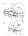
- Fig. 1 is an unwinding purely schematically Station 1 shown, in which a storage unit 2 is arranged.
- This storage unit 2 corresponds in its structure and also the mode of operation to the winding and storage unit described in DE-OS 3 236 866 and the corresponding GB-OS 2 107 681.
- This storage unit 2 has a mobile frame 3 in the form of a bearing block 1, in which the shaft 4 of a cylindrical winding core 5 is rotatably mounted. In a manner known per se, printed products lying on top of one another are wound onto this winding core 5 to form a storage winding 6.
- a supply roll 7 for a winding tape W is further rotatably mounted, which is connected to the winding core 5 and is arranged between the individual winding layers formed by the printed products.
- a first conveyor 8 is arranged for leading away the developed scale formation S 1 in the direction of arrow B.
- This first conveyor device 8 has a first belt conveyor 9 designed as a rocker, which is arranged pivotably about the axis denoted by 9a and is pressed onto the winding 6 by means not shown.
- a second belt conveyor 10 Connected to this belt conveyor 9 is a second belt conveyor 10, which has a higher conveying speed than the belt conveyor 9.
- a stop 11 is arranged in the conveyor path of the latter.
- a second conveyor device 12 is arranged below this stop 11 and thus also the first conveyor device 8, the conveying direction C of which is opposite to the conveying direction B of the first conveyor device 8.
- This second conveyor device 12 has a first conveyor 13 which is inclined with respect to a horizontal and extends rearward beyond the end 8a of the first conveyor device 8.
- Another belt conveyor 14 is connected to this belt conveyor 13.
- FIG. 2 shows a winding station 15 with a storage unit 2, in which a scale formation S together with a winding tape is placed on the winding core 5 of the storage unit 2.
- W is wound up in a manner known per se.
- the scale formation S to be wound up is fed by a belt conveyor 16 which is only partially shown, to which a further belt conveyor 17 designed as a rocker connects.
- the latter is pivotally mounted about its axis designated 17a and is brought into contact with the storage reel 6 by means not shown.
- the direction of conveyance of the two belt conveyors 16 and 17 is denoted by E.
- each printed product 18 lies on the preceding printed product. This means that the leading edge 19 of each printed product 18, which is usually the folded edge, lies on the top of the scale formation S and faces the winding core 5 or the outermost winding layer of the storage roll 6.
- the trailing edge 20 of each printed product 18 is covered by the subsequent printed product 18.
- the printed products 18 only overlap in their edge area.
- the supply spool 7 is driven, as explained in the above-mentioned laid-open publications, and the winding core 5 rotating in the direction of arrow A is slightly braked.
- the printed products 18 now have a different position within the scale formation S detached from the winding 6 and placed on the belt conveyor 9, before the winding.
- each printed product 18 lies on the subsequent printed product, so that the leading edge 20, which formed the trailing edge in the original scale formation S, lies on the underside of the scale formation.
- the printed products 18 are accelerated and separated by this belt conveyor 10, as is shown in FIG. 1 by the printed product designated 18 '.
- the printed product designated 18 ' As a result of this acceleration of the individual printed products 18, they are subtracted from the subsequent printed product 18 "and are thus detached from the latter.
- the printed products separated and separated from the scale formation in this way are now moved against the stop 11 arranged in the conveying path of the printed products 18 conveyed by the first conveying device 8, which is located at a distance from the end 8a of the first conveying device which is at least the size of the printed products 18 corresponds in the conveying direction B.
- the printed products 18 fall down and come to rest on the preceding printed product 18 ′′ ', which has previously been placed on the belt conveyor 13 or on the printed products 18 already located thereon
- Belt conveyors 13 and 14 transport the printed products 18 lying thereon in the opposite direction C.
- the newly formed scale formation S 2 can now be fed to a processing station in which the printed products 18 can thus be processed in the same way as printed products which are fed directly to the processing station in a roll without first being stored temporarily.
- FIGS. 3 and 4 The other embodiment shown in FIGS. 3 and 4 is particularly suitable for changing the position of the printed products within the scale formation in formations in which the printed products only overlap in the edge region.
- the device according to FIG. 3 largely corresponds to the device shown in FIG. 1.
- the same reference numerals are therefore used for corresponding parts in FIGS. 1 and 3. Only the differences between the two embodiments are discussed in more detail below.
- the first conveyor device 8 has two belt conveyors 21 and 22 connected downstream of the belt conveyor 9, which are driven at the same conveying speed as the belt conveyor 9.
- a driver rod 23 is arranged, which is arranged around a to the conveying direction B of the belt conveyors 21 and 22 parallel axis and laterally extending the belt conveyors 21 and 22 axis 23a is driven in the direction of arrow F all round (FIG. 4).
- the movement path of the carrier rod 23 runs essentially at right angles to the direction of movement B of the printed products 18 and between the belt conveyors 21 and 22.
- the carrier rod 23 crosses the movement path of the printed products 18 during its circulation from bottom to top.
- Rollers 24 and 25 are arranged on both sides of the driving rod 23, which co-operate with the belt conveyor 21 or with the belt conveyor 22 and form a gap with these belt conveyors, which must be traversed by the printed products 18. These rollers 24 and 25 prevent the printed products 18 from being lifted off the belt conveyor 21 or 22 when the driver rod 23 acts on the printed products 18 in a manner to be described.
- the revolving driver rod 23 is moved during its orbital movement against the underside 18b of the printed product 18 'located above the space between the two belt conveyors 21 and 22.
- This printed product 18 ' is raised during the further rotation of the driving rod 23. Since this printed product 18 'is held in its rear region between the roller 24 and the belt conveyor 21, the printed product 18' is raised in the region of its leading edge 20 over the trailing edge 19 of the preceding printed product 18 "" and then onto this preceding printed product 18 "” filed as soon as the driver rod 23 no longer acts on this printed product 18 '.
- the preceding printed product 18 "" is prevented from being completely lifted off the belt conveyor 22 by the roller 25.
- the carrier rod 23 consequently reallocates the printed products 18 within the developed scale formation S "in which the leading edge 20 lying underneath after unwinding is brought to the top of the scale formation S, as is the case with the printed product 18" ".
- a scale formation S 2 is obtained with relatively simple means and without re-winding the scale formation S unwound from the storage roll 6, which corresponds to the original scale formation S and can be fed directly to processing stations.
Landscapes
- Engineering & Computer Science (AREA)
- Mechanical Engineering (AREA)
- Separation, Sorting, Adjustment, Or Bending Of Sheets To Be Conveyed (AREA)
- Discharge By Other Means (AREA)
- Folding Of Thin Sheet-Like Materials, Special Discharging Devices, And Others (AREA)
Claims (7)
Priority Applications (2)
| Application Number | Priority Date | Filing Date | Title |
|---|---|---|---|
| AT84109716T ATE31181T1 (de) | 1983-09-05 | 1984-08-16 | Verfahren und vorrichtung zum verarbeiten von von einem speicherwickel abgewickelten flaechigen erzeugnissen, insbesondere druckprodukten. |
| DE8686114956T DE3480083D1 (en) | 1983-09-05 | 1984-08-16 | Method and device for processing flat products, especially printed products, which are unwound from a storage coil |
Applications Claiming Priority (2)
| Application Number | Priority Date | Filing Date | Title |
|---|---|---|---|
| CH4858/83 | 1983-09-05 | ||
| CH4858/83A CH662546A5 (de) | 1983-09-05 | 1983-09-05 | Verfahren und vorrichtung zum verarbeiten von von einem speicherwickel abgewickelten flaechigen erzeugnissen, insbesondere druckprodukten. |
Related Child Applications (3)
| Application Number | Title | Priority Date | Filing Date |
|---|---|---|---|
| EP86114956A Division-Into EP0226007B1 (fr) | 1983-09-05 | 1984-08-16 | Procédé et dispositif pour traiter des produits plats, notamment des imprimés, qui sont déroulés d'une bobine de stockage |
| EP86114956A Division EP0226007B1 (fr) | 1983-09-05 | 1984-08-16 | Procédé et dispositif pour traiter des produits plats, notamment des imprimés, qui sont déroulés d'une bobine de stockage |
| EP86114956.5 Division-Into | 1986-10-28 |
Publications (2)
| Publication Number | Publication Date |
|---|---|
| EP0136498A1 EP0136498A1 (fr) | 1985-04-10 |
| EP0136498B1 true EP0136498B1 (fr) | 1987-12-02 |
Family
ID=4283773
Family Applications (2)
| Application Number | Title | Priority Date | Filing Date |
|---|---|---|---|
| EP86114956A Expired EP0226007B1 (fr) | 1983-09-05 | 1984-08-16 | Procédé et dispositif pour traiter des produits plats, notamment des imprimés, qui sont déroulés d'une bobine de stockage |
| EP84109716A Expired EP0136498B1 (fr) | 1983-09-05 | 1984-08-16 | Procédé et dispositif pour convertir des produits plans se déroulant de bobines d'accumulation, notamment produits imprimés |
Family Applications Before (1)
| Application Number | Title | Priority Date | Filing Date |
|---|---|---|---|
| EP86114956A Expired EP0226007B1 (fr) | 1983-09-05 | 1984-08-16 | Procédé et dispositif pour traiter des produits plats, notamment des imprimés, qui sont déroulés d'une bobine de stockage |
Country Status (6)
| Country | Link |
|---|---|
| US (1) | US4595192A (fr) |
| EP (2) | EP0226007B1 (fr) |
| JP (1) | JPH0829877B2 (fr) |
| AT (1) | ATE47121T1 (fr) |
| CH (1) | CH662546A5 (fr) |
| DE (1) | DE3467886D1 (fr) |
Families Citing this family (9)
| Publication number | Priority date | Publication date | Assignee | Title |
|---|---|---|---|---|
| CH657115A5 (de) * | 1982-06-03 | 1986-08-15 | Ferag Ag | Verfahren und vorrichtung zum verarbeiten von in einer schuppenformation anfallenden druckprodukten. |
| DE3632517A1 (de) * | 1986-09-22 | 1988-03-24 | Siemens Ag | Vorrichtung zum aufzeichnen von bildinformationen auf jeweils beiden seiten von aufzeichnungsblaettern |
| DE3862535D1 (de) * | 1987-07-21 | 1991-05-29 | Ferag Ag | Verfahren und vorrichtung zum trennen von in schuppenformation anfallenden erzeugnissen, insbesondere druckprodukten. |
| EP0300179B1 (fr) * | 1987-07-24 | 1991-03-27 | Ferag AG | Procédé et dispositif pour alimenter un séparateur avec des imprimés |
| CH690715A5 (de) * | 1995-07-27 | 2000-12-29 | Ferag Ag | Fördereinrichtung für Druckereierzeugnisse. |
| DE19630762C2 (de) * | 1996-07-31 | 2001-06-21 | Hans Peter Thrandorf | Verfahren und Vorrichtung zur Bildung von Schuppenformationen bedruckter Bogen |
| US6193227B1 (en) * | 1997-04-28 | 2001-02-27 | Grapha-Holding Ag | Continuously feeding sheets with coil unwind control |
| JP3764838B2 (ja) * | 2000-03-17 | 2006-04-12 | 日立オムロンターミナルソリューションズ株式会社 | 紙幣収納放出装置及び紙幣収納放出装置を備えた紙幣取扱装置 |
| US7854331B2 (en) * | 2008-01-15 | 2010-12-21 | Cormark, Inc. | Self storing bicycle display |
Family Cites Families (12)
| Publication number | Priority date | Publication date | Assignee | Title |
|---|---|---|---|---|
| DE1272310B (de) * | 1962-12-05 | 1968-07-11 | Bonnierfoeretagen Ab | Vorrichtung zum Ablegen von ueberlappt gefoerderten Zeitungen oder anderer gefalzterDruckerzeugnisse |
| US3827545A (en) * | 1972-12-04 | 1974-08-06 | Scott Paper Co | Method and apparatus for changing the spacing between discrete, flexible web product |
| US4083277A (en) * | 1976-06-21 | 1978-04-11 | Walter Edward Lotz | Method and means for re-spacing chip steaks on a conveyor |
| US4135616A (en) * | 1977-05-06 | 1979-01-23 | Guntert & Pellaton, Inc. | Method and apparatus for stacking pasta strips |
| DE2725547C2 (de) * | 1977-06-07 | 1983-12-22 | De La Rue Giori S.A., 1003 Lausanne | Verfahren und Vorrichtung zum fächerartigen Übereinanderschieben von bogen- oder heftförmigen Gegenständen |
| CH623286A5 (fr) * | 1977-10-24 | 1981-05-29 | Ferag Ag | |
| CH623288A5 (fr) * | 1977-10-24 | 1981-05-29 | Ferag Ag | |
| US4218743A (en) * | 1978-07-17 | 1980-08-19 | International Business Machines Corporation | Address translation apparatus |
| CH642602A5 (de) * | 1980-07-15 | 1984-04-30 | Ferag Ag | Einrichtung zum stapeln von im schuppenstrom anfallenden druckprodukten, wie zeitungen, zeitschriften und dergleichen. |
| CH652701A5 (de) * | 1981-02-03 | 1985-11-29 | Ferag Ag | Verfahren und einrichtung zur erzielung eines langzeitpressungseffekts bei druckprodukten, insbesondere zeitungen. |
| CH652379A5 (de) * | 1981-09-18 | 1985-11-15 | Ferag Ag | Wickelkoerper zum aufwickeln von kontinuierlich anfallenden flaechengebilden, insbesondere von druckprodukten in schuppenformation. |
| CH657114A5 (de) * | 1982-06-02 | 1986-08-15 | Ferag Ag | Verfahren und vorrichtung zum verarbeiten von in einer schuppenformation anfallenden flaechigen erzeugnissen, insbesondere druckprodukten. |
-
1983
- 1983-09-05 CH CH4858/83A patent/CH662546A5/de not_active IP Right Cessation
-
1984
- 1984-08-16 AT AT86114956T patent/ATE47121T1/de not_active IP Right Cessation
- 1984-08-16 DE DE8484109716T patent/DE3467886D1/de not_active Expired
- 1984-08-16 EP EP86114956A patent/EP0226007B1/fr not_active Expired
- 1984-08-16 EP EP84109716A patent/EP0136498B1/fr not_active Expired
- 1984-08-27 US US06/644,793 patent/US4595192A/en not_active Expired - Fee Related
- 1984-09-03 JP JP59182883A patent/JPH0829877B2/ja not_active Expired - Lifetime
Also Published As
| Publication number | Publication date |
|---|---|
| CH662546A5 (de) | 1987-10-15 |
| EP0136498A1 (fr) | 1985-04-10 |
| JPS6071456A (ja) | 1985-04-23 |
| ATE47121T1 (de) | 1989-10-15 |
| DE3467886D1 (en) | 1988-01-14 |
| EP0226007A1 (fr) | 1987-06-24 |
| EP0226007B1 (fr) | 1989-10-11 |
| US4595192A (en) | 1986-06-17 |
| JPH0829877B2 (ja) | 1996-03-27 |
Similar Documents
| Publication | Publication Date | Title |
|---|---|---|
| EP0075121B1 (fr) | Dispositif pour étirer des produits plats délivrés en formation imbriquée, en particulier des produits imprimés | |
| DE69200163T2 (de) | Vorrichtung zum Ankleben des Endes von Rollen aus Bahnmaterial. | |
| DE3145491C2 (fr) | ||
| DE3244663C2 (de) | Verfahren und Vorrichtung zur Entnahme von auf einen Wickelkern aufgewickelten flächigen Erzeugnissen, vorzugsweise Druckprodukten | |
| AT395143B (de) | Verfahren und vorrichtung zum zwischenspeichern von in einem schuppenstrom anfallenden druckprodukten | |
| CH659232A5 (de) | Vorrichtung zum wenden von aus druckbogen bestehenden teilschuppen. | |
| EP0128334B1 (fr) | Procédé et dispositif pour le stockage intermédiaire des imprimés arrivant en formation imbriquée | |
| DE2939277A1 (de) | Verfahren und vorrichtung zum abbremsen und ueberlappen von papierbogen | |
| EP0368009B1 (fr) | Procédé et dispositif pour délivrer des articles d'imprimerie | |
| EP1188670A1 (fr) | Procédé et machine pour envelopper des produits imprimés dans un matériau d' emballage | |
| EP0417622A1 (fr) | Procédé et dispositif pour le transport de produits imprimés arrivant en formation imbriquée | |
| EP0136498B1 (fr) | Procédé et dispositif pour convertir des produits plans se déroulant de bobines d'accumulation, notamment produits imprimés | |
| DE19533086A1 (de) | Verfahren und Vorrichtung zum Stapeln von flächigen Erzeugnissen, insbesondere Druckereiprodukten | |
| EP0054735A2 (fr) | Dispositif de fabrication de rouleaux de bandes formées à partir de feuilles souples imbriqueés | |
| DE3301852A1 (de) | Verfahren und vorrichtung zum verarbeiten von zwei jeweils durch flaechige erzeugnisse, vorzugsweise druckprodukte, gebildeten formationen | |
| AT394020B (de) | Vorrichtung zum speichern von kontinuierlich, insbesondere in einem schuppenstrom zugefuehrten flaechigen erzeugnissen | |
| DE3409548C2 (fr) | ||
| EP0499691A1 (fr) | Procédé pour traiter des produits imprimés alimentés de façon continue en une formation imbriquée ainsi que dispositif pour la mise en oeuvre dudit procédé | |
| DE68915019T2 (de) | Verfahren und Vorrichtung zum Einrahmen von photographischen Filmen. | |
| DE2112353A1 (de) | Verfahren und Vorrichtung zum Bilden von Paketen aus flachen Werkstuecken,insbesondere aus Schlauchabschnitten | |
| CH657114A5 (de) | Verfahren und vorrichtung zum verarbeiten von in einer schuppenformation anfallenden flaechigen erzeugnissen, insbesondere druckprodukten. | |
| DE3730132A1 (de) | Blechtransportvorrichtung | |
| DE69609229T2 (de) | Zwischenspeicherungssystem zur Herstellung von Zeitungen | |
| DE3926607A1 (de) | Vorrichtung zum foerdern und oeffnen von falzbogen | |
| EP0953534A2 (fr) | Système pour conduire en adaptant le courant chevauchant de produits sous forme de feuilles |
Legal Events
| Date | Code | Title | Description |
|---|---|---|---|
| PUAI | Public reference made under article 153(3) epc to a published international application that has entered the european phase |
Free format text: ORIGINAL CODE: 0009012 |
|
| AK | Designated contracting states |
Designated state(s): AT BE DE FR GB IT NL SE |
|
| 17P | Request for examination filed |
Effective date: 19850223 |
|
| RTI1 | Title (correction) | ||
| ITF | It: translation for a ep patent filed | ||
| GRAA | (expected) grant |
Free format text: ORIGINAL CODE: 0009210 |
|
| AK | Designated contracting states |
Kind code of ref document: B1 Designated state(s): AT BE DE FR GB IT NL SE |
|
| REF | Corresponds to: |
Ref document number: 31181 Country of ref document: AT Date of ref document: 19871215 Kind code of ref document: T |
|
| REF | Corresponds to: |
Ref document number: 3467886 Country of ref document: DE Date of ref document: 19880114 |
|
| ET | Fr: translation filed | ||
| GBT | Gb: translation of ep patent filed (gb section 77(6)(a)/1977) | ||
| PLBE | No opposition filed within time limit |
Free format text: ORIGINAL CODE: 0009261 |
|
| STAA | Information on the status of an ep patent application or granted ep patent |
Free format text: STATUS: NO OPPOSITION FILED WITHIN TIME LIMIT |
|
| 26N | No opposition filed | ||
| PGFP | Annual fee paid to national office [announced via postgrant information from national office to epo] |
Ref country code: FR Payment date: 19920714 Year of fee payment: 9 |
|
| PGFP | Annual fee paid to national office [announced via postgrant information from national office to epo] |
Ref country code: BE Payment date: 19920717 Year of fee payment: 9 |
|
| PGFP | Annual fee paid to national office [announced via postgrant information from national office to epo] |
Ref country code: AT Payment date: 19920721 Year of fee payment: 9 |
|
| ITTA | It: last paid annual fee | ||
| PGFP | Annual fee paid to national office [announced via postgrant information from national office to epo] |
Ref country code: NL Payment date: 19920831 Year of fee payment: 9 |
|
| PGFP | Annual fee paid to national office [announced via postgrant information from national office to epo] |
Ref country code: SE Payment date: 19930723 Year of fee payment: 10 |
|
| PG25 | Lapsed in a contracting state [announced via postgrant information from national office to epo] |
Ref country code: AT Effective date: 19930816 |
|
| PG25 | Lapsed in a contracting state [announced via postgrant information from national office to epo] |
Ref country code: BE Effective date: 19930831 |
|
| BERE | Be: lapsed |
Owner name: FERAG A.G. Effective date: 19930831 |
|
| PG25 | Lapsed in a contracting state [announced via postgrant information from national office to epo] |
Ref country code: NL Effective date: 19940301 |
|
| NLV4 | Nl: lapsed or anulled due to non-payment of the annual fee | ||
| PG25 | Lapsed in a contracting state [announced via postgrant information from national office to epo] |
Ref country code: FR Effective date: 19940429 |
|
| REG | Reference to a national code |
Ref country code: FR Ref legal event code: ST |
|
| PG25 | Lapsed in a contracting state [announced via postgrant information from national office to epo] |
Ref country code: SE Effective date: 19940817 |
|
| EAL | Se: european patent in force in sweden |
Ref document number: 84109716.5 |
|
| EUG | Se: european patent has lapsed |
Ref document number: 84109716.5 |
|
| PGFP | Annual fee paid to national office [announced via postgrant information from national office to epo] |
Ref country code: DE Payment date: 19950717 Year of fee payment: 12 |
|
| PGFP | Annual fee paid to national office [announced via postgrant information from national office to epo] |
Ref country code: GB Payment date: 19950721 Year of fee payment: 12 |
|
| PG25 | Lapsed in a contracting state [announced via postgrant information from national office to epo] |
Ref country code: GB Effective date: 19960816 |
|
| GBPC | Gb: european patent ceased through non-payment of renewal fee |
Effective date: 19960816 |
|
| PG25 | Lapsed in a contracting state [announced via postgrant information from national office to epo] |
Ref country code: DE Effective date: 19970501 |