EP0136498B1 - Method and device for the processing of flat products, especially printed products, which are unwound from a storage coil - Google Patents
Method and device for the processing of flat products, especially printed products, which are unwound from a storage coil Download PDFInfo
- Publication number
- EP0136498B1 EP0136498B1 EP84109716A EP84109716A EP0136498B1 EP 0136498 B1 EP0136498 B1 EP 0136498B1 EP 84109716 A EP84109716 A EP 84109716A EP 84109716 A EP84109716 A EP 84109716A EP 0136498 B1 EP0136498 B1 EP 0136498B1
- Authority
- EP
- European Patent Office
- Prior art keywords
- conveyor
- product
- products
- region
- advancing
- Prior art date
- Legal status (The legal status is an assumption and is not a legal conclusion. Google has not performed a legal analysis and makes no representation as to the accuracy of the status listed.)
- Expired
Links
- 238000003860 storage Methods 0.000 title claims abstract description 22
- 238000000034 method Methods 0.000 title claims description 7
- 230000015572 biosynthetic process Effects 0.000 claims abstract description 61
- 230000001133 acceleration Effects 0.000 abstract description 2
- 238000005755 formation reaction Methods 0.000 description 51
- 238000004804 winding Methods 0.000 description 22
- 230000001419 dependent effect Effects 0.000 description 1
- 238000011161 development Methods 0.000 description 1
- 230000018109 developmental process Effects 0.000 description 1
- 238000012432 intermediate storage Methods 0.000 description 1
- 230000008707 rearrangement Effects 0.000 description 1
Images

Classifications
-
- B—PERFORMING OPERATIONS; TRANSPORTING
- B65—CONVEYING; PACKING; STORING; HANDLING THIN OR FILAMENTARY MATERIAL
- B65H—HANDLING THIN OR FILAMENTARY MATERIAL, e.g. SHEETS, WEBS, CABLES
- B65H5/00—Feeding articles separated from piles; Feeding articles to machines
- B65H5/28—Feeding articles stored in rolled or folded bands
-
- B—PERFORMING OPERATIONS; TRANSPORTING
- B65—CONVEYING; PACKING; STORING; HANDLING THIN OR FILAMENTARY MATERIAL
- B65H—HANDLING THIN OR FILAMENTARY MATERIAL, e.g. SHEETS, WEBS, CABLES
- B65H29/00—Delivering or advancing articles from machines; Advancing articles to or into piles
- B65H29/006—Winding articles into rolls
-
- B—PERFORMING OPERATIONS; TRANSPORTING
- B65—CONVEYING; PACKING; STORING; HANDLING THIN OR FILAMENTARY MATERIAL
- B65H—HANDLING THIN OR FILAMENTARY MATERIAL, e.g. SHEETS, WEBS, CABLES
- B65H2301/00—Handling processes for sheets or webs
- B65H2301/40—Type of handling process
- B65H2301/41—Winding, unwinding
- B65H2301/419—Winding, unwinding from or to storage, i.e. the storage integrating winding or unwinding means
- B65H2301/4192—Winding, unwinding from or to storage, i.e. the storage integrating winding or unwinding means for handling articles of limited length in shingled formation
- B65H2301/41922—Winding, unwinding from or to storage, i.e. the storage integrating winding or unwinding means for handling articles of limited length in shingled formation and wound together with single belt like members
-
- B—PERFORMING OPERATIONS; TRANSPORTING
- B65—CONVEYING; PACKING; STORING; HANDLING THIN OR FILAMENTARY MATERIAL
- B65H—HANDLING THIN OR FILAMENTARY MATERIAL, e.g. SHEETS, WEBS, CABLES
- B65H2701/00—Handled material; Storage means
- B65H2701/10—Handled articles or webs
- B65H2701/19—Specific article or web
- B65H2701/1932—Signatures, folded printed matter, newspapers or parts thereof and books
-
- Y—GENERAL TAGGING OF NEW TECHNOLOGICAL DEVELOPMENTS; GENERAL TAGGING OF CROSS-SECTIONAL TECHNOLOGIES SPANNING OVER SEVERAL SECTIONS OF THE IPC; TECHNICAL SUBJECTS COVERED BY FORMER USPC CROSS-REFERENCE ART COLLECTIONS [XRACs] AND DIGESTS
- Y10—TECHNICAL SUBJECTS COVERED BY FORMER USPC
- Y10S—TECHNICAL SUBJECTS COVERED BY FORMER USPC CROSS-REFERENCE ART COLLECTIONS [XRACs] AND DIGESTS
- Y10S271/00—Sheet feeding or delivering
- Y10S271/902—Reverse direction of sheet movement
Definitions
- the present invention relates to a method and a device for processing flat products, in particular printed products, unwound from a storage roll in a scale formation, according to the preamble of claim 1 and claim 3.
- the present invention is based on the object of creating a method and a device of the type mentioned at the outset which, with as little effort as possible, allow the products to be temporarily stored on a reel in the position of a processing station which is required for perfect further processing to forward.
- each product may stick together in certain cases.
- any products that are contiguous are separated again.
- each product thus forms an association with the other products again, but the individual products are no longer connected to the neighboring products, which is a prerequisite for correct, individual handling of the individual products.
- Fig. 1 is an unwinding purely schematically Station 1 shown, in which a storage unit 2 is arranged.
- This storage unit 2 corresponds in its structure and also the mode of operation to the winding and storage unit described in DE-OS 3 236 866 and the corresponding GB-OS 2 107 681.
- This storage unit 2 has a mobile frame 3 in the form of a bearing block 1, in which the shaft 4 of a cylindrical winding core 5 is rotatably mounted. In a manner known per se, printed products lying on top of one another are wound onto this winding core 5 to form a storage winding 6.
- a supply roll 7 for a winding tape W is further rotatably mounted, which is connected to the winding core 5 and is arranged between the individual winding layers formed by the printed products.
- a first conveyor 8 is arranged for leading away the developed scale formation S 1 in the direction of arrow B.
- This first conveyor device 8 has a first belt conveyor 9 designed as a rocker, which is arranged pivotably about the axis denoted by 9a and is pressed onto the winding 6 by means not shown.
- a second belt conveyor 10 Connected to this belt conveyor 9 is a second belt conveyor 10, which has a higher conveying speed than the belt conveyor 9.
- a stop 11 is arranged in the conveyor path of the latter.
- a second conveyor device 12 is arranged below this stop 11 and thus also the first conveyor device 8, the conveying direction C of which is opposite to the conveying direction B of the first conveyor device 8.
- This second conveyor device 12 has a first conveyor 13 which is inclined with respect to a horizontal and extends rearward beyond the end 8a of the first conveyor device 8.
- Another belt conveyor 14 is connected to this belt conveyor 13.
- FIG. 2 shows a winding station 15 with a storage unit 2, in which a scale formation S together with a winding tape is placed on the winding core 5 of the storage unit 2.
- W is wound up in a manner known per se.
- the scale formation S to be wound up is fed by a belt conveyor 16 which is only partially shown, to which a further belt conveyor 17 designed as a rocker connects.
- the latter is pivotally mounted about its axis designated 17a and is brought into contact with the storage reel 6 by means not shown.
- the direction of conveyance of the two belt conveyors 16 and 17 is denoted by E.
- each printed product 18 lies on the preceding printed product. This means that the leading edge 19 of each printed product 18, which is usually the folded edge, lies on the top of the scale formation S and faces the winding core 5 or the outermost winding layer of the storage roll 6.
- the trailing edge 20 of each printed product 18 is covered by the subsequent printed product 18.
- the printed products 18 only overlap in their edge area.
- the supply spool 7 is driven, as explained in the above-mentioned laid-open publications, and the winding core 5 rotating in the direction of arrow A is slightly braked.
- the printed products 18 now have a different position within the scale formation S detached from the winding 6 and placed on the belt conveyor 9, before the winding.
- each printed product 18 lies on the subsequent printed product, so that the leading edge 20, which formed the trailing edge in the original scale formation S, lies on the underside of the scale formation.
- the printed products 18 are accelerated and separated by this belt conveyor 10, as is shown in FIG. 1 by the printed product designated 18 '.
- the printed product designated 18 ' As a result of this acceleration of the individual printed products 18, they are subtracted from the subsequent printed product 18 "and are thus detached from the latter.
- the printed products separated and separated from the scale formation in this way are now moved against the stop 11 arranged in the conveying path of the printed products 18 conveyed by the first conveying device 8, which is located at a distance from the end 8a of the first conveying device which is at least the size of the printed products 18 corresponds in the conveying direction B.
- the printed products 18 fall down and come to rest on the preceding printed product 18 ′′ ', which has previously been placed on the belt conveyor 13 or on the printed products 18 already located thereon
- Belt conveyors 13 and 14 transport the printed products 18 lying thereon in the opposite direction C.
- the newly formed scale formation S 2 can now be fed to a processing station in which the printed products 18 can thus be processed in the same way as printed products which are fed directly to the processing station in a roll without first being stored temporarily.
- FIGS. 3 and 4 The other embodiment shown in FIGS. 3 and 4 is particularly suitable for changing the position of the printed products within the scale formation in formations in which the printed products only overlap in the edge region.
- the device according to FIG. 3 largely corresponds to the device shown in FIG. 1.
- the same reference numerals are therefore used for corresponding parts in FIGS. 1 and 3. Only the differences between the two embodiments are discussed in more detail below.
- the first conveyor device 8 has two belt conveyors 21 and 22 connected downstream of the belt conveyor 9, which are driven at the same conveying speed as the belt conveyor 9.
- a driver rod 23 is arranged, which is arranged around a to the conveying direction B of the belt conveyors 21 and 22 parallel axis and laterally extending the belt conveyors 21 and 22 axis 23a is driven in the direction of arrow F all round (FIG. 4).
- the movement path of the carrier rod 23 runs essentially at right angles to the direction of movement B of the printed products 18 and between the belt conveyors 21 and 22.
- the carrier rod 23 crosses the movement path of the printed products 18 during its circulation from bottom to top.
- Rollers 24 and 25 are arranged on both sides of the driving rod 23, which co-operate with the belt conveyor 21 or with the belt conveyor 22 and form a gap with these belt conveyors, which must be traversed by the printed products 18. These rollers 24 and 25 prevent the printed products 18 from being lifted off the belt conveyor 21 or 22 when the driver rod 23 acts on the printed products 18 in a manner to be described.
- the revolving driver rod 23 is moved during its orbital movement against the underside 18b of the printed product 18 'located above the space between the two belt conveyors 21 and 22.
- This printed product 18 ' is raised during the further rotation of the driving rod 23. Since this printed product 18 'is held in its rear region between the roller 24 and the belt conveyor 21, the printed product 18' is raised in the region of its leading edge 20 over the trailing edge 19 of the preceding printed product 18 "" and then onto this preceding printed product 18 "” filed as soon as the driver rod 23 no longer acts on this printed product 18 '.
- the preceding printed product 18 "" is prevented from being completely lifted off the belt conveyor 22 by the roller 25.
- the carrier rod 23 consequently reallocates the printed products 18 within the developed scale formation S "in which the leading edge 20 lying underneath after unwinding is brought to the top of the scale formation S, as is the case with the printed product 18" ".
- a scale formation S 2 is obtained with relatively simple means and without re-winding the scale formation S unwound from the storage roll 6, which corresponds to the original scale formation S and can be fed directly to processing stations.
Landscapes
- Engineering & Computer Science (AREA)
- Mechanical Engineering (AREA)
- Separation, Sorting, Adjustment, Or Bending Of Sheets To Be Conveyed (AREA)
- Discharge By Other Means (AREA)
- Folding Of Thin Sheet-Like Materials, Special Discharging Devices, And Others (AREA)
Abstract
Description
Die vorliegende Erfindung betrifft ein Verfahren sowie eine Vorrichtung zum Verarbeiten von in einer Schuppenformation von einem Speicherwickel abgewickelten flächigen Erzeugnissen, insbesondere Druckprodukten, gemäss Oberbegriff des Anspruches 1 bzw. des Anspruches 3.The present invention relates to a method and a device for processing flat products, in particular printed products, unwound from a storage roll in a scale formation, according to the preamble of
Aus der DE-A-3 123 888 und der entsprechenden GB-A- 2 081 230 ist es bekannt, die z. B. von einer Rotationsdruckmaschine ausgestossenen und in einer Schuppenformation anfallenden Druckprodukte vor der Weiterverarbeitung zur Zwischenspeicherung aufzuwickeln. In der von diesem Speicherwickel wieder abgewickelten Schuppenformation nehmen die Druckprodukte jedoch eine andere gegenseitige Lage ein als in der ursprünglich anfallenden Schuppenformation, d. h. dass nach dem Abwickeln die in der ursprünglichen Schuppenformation vorlaufende Kante der Druckprodukte zur nachlaufenden Kante wird. Die Weiterverarbeitung der vom Speicherwickel abgewickelten Schuppenformation ist aus diesem Grunde nicht ganz problemlos, ist es doch in vielen Fällen für die Weiterverarbeitung erforderlich, dass die Druckprodukte innerhalb der Schuppenformation ihre ursprüngliche gegenseitige Lage einnehmen.From DE-A-3 123 888 and the corresponding GB-A-2 081 230 it is known that the z. B. ejected from a rotary printing machine and accumulating in a scale formation of printed products before further processing for intermediate storage. However, in the imbricated formation that is unwound from this storage roll, the printed products assume a different mutual position than in the originally occurring imbricated formation, i. H. that after unwinding, the leading edge of the printed products in the original scale formation becomes the trailing edge. For this reason, the further processing of the scale formation unwound from the storage roll is not without problems, since in many cases it is necessary for the further processing that the printed products assume their original mutual position within the scale formation.
Aus der DE-A-3 151 860 bzw. der entsprechenden GB-A-2092557 ist nun eine Einrichtung bekannt, bei der die in Schuppenformation von einem ersten Wickel abgewickelten Druckprodukte zu einem zweiten Wickel aufgewickelt werden. In der von diesem zweiten Wickel abgewickelten Schuppenformation nehmen nun die Druckprodukte eine gegenseitige Lage ein, die der Lage der Druckprodukte in der ursprünglichen Schuppenformation entspricht. Mit dieser bekannten Einrichtung lässt sich daher die Forderung erfüllen, dass nach dem Zwischenspeichern der Druckprodukte in einem Wickel die Druckprodukte innerhalb der Schuppenformation die ursprüngliche gegenseitige Lage einnehmen. Doch ist hierfür ein erheblicher konstruktiver Aufwand erforderlich. Zudem wird die Verarbeitungszeit erhöht, was in gewissen Fällen unerwünscht ist.From DE-A-3 151 860 or the corresponding GB-A-2092557 a device is now known in which the printed products unwound from a first roll in a scale formation are wound up to form a second roll. In the scale formation unwound from this second roll, the printed products now assume a mutual position which corresponds to the position of the printed products in the original scale formation. With this known device, the requirement can therefore be met that after the temporary storage of the printed products in a roll, the printed products assume the original mutual position within the scale formation. However, this requires considerable design effort. In addition, the processing time is increased, which is undesirable in certain cases.
Aus der US-A-4,214,743 ist es weiter bekannt, Druckprodukte in einer Schuppenformation, in der jedes Druckprodukt dachziegelartig auf dem vorlaufenden Druckprodukt aufliegt, entlang einer ersten Förderstrecke zu fördern. Am Ende dieser ersten Förderstrecke werden die Druckprodukte nach unten auf eine zweite Förderstrecke fallengelassen, deren Förderrichtung derjenigen der ersten Förderstrecke entgegengesetzt ist. Auf dem diese zweite Förderstrecke festlegenden Förderer wird wieder eine Schuppenformation gebildet, in der jedoch die in der ersten Förderstrecke vorlaufende und oben liegende Kante der Druckprodukte nun die nachlaufende und unten liegende Kante bildet.From US-A-4,214,743 it is further known to convey printed products in a scale formation, in which each printed product rests on the leading printed product in the manner of a roof tile, along a first conveying path. At the end of this first conveying path, the printed products are dropped down onto a second conveying path, the conveying direction of which is opposite to that of the first conveying path. A scale formation is again formed on the conveyor defining this second conveying path, in which, however, the edge of the printed products leading and lying in the first conveying path now forms the trailing and lying edge.
Der vorliegenden Erfindung liegt nun die Aufgabe zugrunde, ein Verfahren bzw. eine Vorrichtung der eingangs genannten Art zu schaffen, das bzw. die mit möglichst geringem Aufwand erlaubt, die Erzeugnisse nach einer Zwischenspeicherung auf einem Wickel in der für eine einwandfreie Weiterverarbeitung erforderlichen Lage einer Verarbeitungsstation zuzuleiten.The present invention is based on the object of creating a method and a device of the type mentioned at the outset which, with as little effort as possible, allow the products to be temporarily stored on a reel in the position of a processing station which is required for perfect further processing to forward.
Diese Aufgabe wird erfindungsgemäss durch die Merkmale des kennzeichnenden Teils des Anspruches 1 bzw. des Anspruches 3 gelöst.This object is achieved according to the invention by the features of the characterizing part of
Durch das Ändern der gegenseitigen Lage der sich überlappenden Bereiche der Erzeugnisse vor dem Ende der ersten Förderstrecke und das anschliessende dachziegelartige Aufeinanderlegen der am Ende dieser ersten Förderstrecke freigegebenen Erzeugnisse auf eine unterhalb dieser ersten Förderstrecke angeordnete zweite Fördereinrichtung mit entgegengesetzter Förderrichtung wird auf letzterer wieder eine Schuppenformation gebildet, in der die Erzeugnisse dieselbe gegenseitige Lage einnehmen wie vor dem Aufwickeln. Diese Änderung der Lage der Erzeugnisse innerhalb ihrer Formation kann somit mit verhältnismässig einfachen Mitteln durchgeführt werden. Am Ende der ersten Förderstrecke liegen die Erzeugnisse zumindest mit ihrer vorlaufenden Kante und auch mit ihrer Ober- und Unterseite frei, was auf einfache Weise eine Kontrolle, z. B. ein Zählen, der Erzeugnisse ermöglicht.By changing the mutual position of the overlapping areas of the products before the end of the first conveyor section and the subsequent roof-tile stacking of the products released at the end of this first conveyor section onto a second conveyor device arranged below this first conveyor section with an opposite conveyor direction, a scale formation is again formed on the latter in which the products are in the same mutual position as before the winding. This change in the position of the products within their formation can thus be carried out with relatively simple means. At the end of the first conveyor line, the products are at least exposed with their leading edge and also with their top and bottom sides, which is a simple way of checking, e.g. B. a count that enables products.
Infolge des im Speicherwickel herrschenden Pressdruckes kann es in gewissen Fällen zum Aneinanderhaften der Erzeugnisse kommen. Durch das Lösen der Erzeugnisse voneinander am Ende der ersten Förderstrecke werden gegebenenfalls aneinanderhängende Erzeugnisse wieder voneinander getrennt. In der durch die zweite Fördereinrichtung weggeführten Schuppenformation bildet somit jedes Erzeugnis mit den übrigen Erzeugnissen wieder einen Verband, doch sind die einzelnen Erzeugnisse mit den benachbarten Erzeugnissen nicht mehr miteinander verbunden, was eine Voraussetzung für ein einwandfreies, individuelles Handhaben der einzelnen Erzeugnisse ist.As a result of the pressing pressure prevailing in the storage roll, the products may stick together in certain cases. By detaching the products from each other at the end of the first conveyor line, any products that are contiguous are separated again. In the scale formation led away by the second conveying device, each product thus forms an association with the other products again, but the individual products are no longer connected to the neighboring products, which is a prerequisite for correct, individual handling of the individual products.
Bevorzugte Weiterausbildungen der vorliegenden Erfindung bilden Gegenstand der abhängigen Ansprüche.Preferred further developments of the present invention form the subject of the dependent claims.
Im folgenden wird anhand der Zeichnung die Erfindung näher erläutert. Es zeigt rein schematisch :
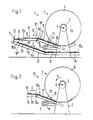
- Fig. 1 in Seitenansicht eine Vorrichtung zum Abwickeln und Wegführen von in einer Schuppenformation in einem Speicherwickel zwischengespeicherten Druckprodukten,
- Fig. 2 eine Vorrichtung zur Bildung eines Speicherwickels in Seitenansicht,
- Fig. 3 in Seitenansicht eine Ausführungsform einer Vorrichtung zum Abwickeln und Wegführen von in Schuppenformation in einem Speicherwickel zwischengespeicherten Druckprodukten, und
- Fig. 4 einen Schnitt entlang der Linie IV-IV in Fig. 3.
- 1 is a side view of a device for unwinding and carrying away printed products temporarily stored in a scale formation in a storage roll,
- 2 shows a device for forming a storage roll in a side view,
- 3 shows a side view of an embodiment of an apparatus for unwinding and carrying away printed products temporarily stored in a scale formation in a storage roll, and
- 4 shows a section along the line IV-IV in FIG. 3.
In der Fig. 1 ist rein schematisch eine Abwickelstation 1 gezeigt, in welcher eine Speichereinheit 2 angeordnet ist. Letztere entspricht in ihrem Aufbau und auch der Wirkungsweise der in der DE-OS 3 236 866 bzw. der entsprechenden GB-OS 2 107 681 beschriebenen Aufwickel- und Speichereinheit. Diese Speichereinheit 2 weist ein mobiles Gestell 3 in der Form eines Lagerbockes 1, in welchem die Welle 4 eines zylindrischen Wickelkernes 5 drehbar gelagert ist, auf. Auf diesen Wickelkern 5 sind auf an sich bekannte Weise schuppenförmig übereinanderliegende Druckprodukte zu einem Speicherwickel 6 aufgewickelt. Im Gestell 3 ist weiter drehbar eine Vorratsrolle 7 für ein Wickelband W gelagert, das mit dem Wickelkern 5 verbunden ist und zwischen den einzelnen durch die Druckprodukte gebildeten Wicklungslagen angeordnet ist.In Fig. 1 is an unwinding purely schematically
Unterhalb des Wickelkernes 5 ist eine erste Fördereinrichtung 8 zum Wegführen der abgewickelten Schuppenformation S1 in Richtung des Pfeiles B angeordnet. Diese erste Fördereinrichtung 8 weist einen ersten, als Wippe ausgebildeten Bandförderer 9 auf, der um die mit 9a bezeichnete Achse schwenkbar angeordnet ist und durch nicht dargestellte Mittel an den Wickel 6 angedrückt wird. An diesen Bandförderer 9 schliesst ein zweiter Bandförderer 10 an, der eine höhere Fördergeschwindigkeit aufweist als der Bandförderer 9. In einem Abstand vom Ende 8a der ersten Fördereinrichtung 8 ist im Förderweg der letzteren ein Anschlag 11 angeordnet. Unterhalb dieses Anschlages 11 und somit auch der ersten Fördereinrichtung 8 ist eine zweite Fördereinrichtung 12 angeordnet, deren Förderrichtung C der Förderrichtung B der ersten Fördereinrichtung 8 entgegengesetzt ist. Diese zweite Fördereinrichtung 12 weist einen ersten Förderer 13 auf, der gegenüber einer Horizontalen geneigt ist und sich nach hinten über das Ende 8a der ersten Fördereinrichtung 8 hinaus erstreckt. An diesen Bandförderer 13 schliesst ein weiterer Bandförderer 14 an.Below the winding
In Fig. 2 ist der Vollständigkeit halber eine Aufwickelstation 15 mit einer Speichereinheit 2 dargestellt, in der auf den Wickelkern 5 der Speichereinheit 2 eine Schuppenformation S zusammen mit einem Wickelband. W auf an sich bekannte Weise aufgewickelt wird. Die aufzuwikkelnde Schuppenformation S wird durch einen nur teilweise dargestellten Bandförderer 16 zugeführt, an den ein als Wippe ausgebildeter weiterer Bandförderer 17 anschliesst. Letzterer ist um seine mit 17a bezeichnete Achse schwenkbar gelagert und wird durch nicht näher dargestellte Mittel am Speicherwickel 6 zur Anlage gebracht. Die Förderrichtung der beiden Bandförderer 16 und 17 ist mit E bezeichnet.For the sake of completeness, FIG. 2 shows a
Das Auf- und Abwickeln der Schuppenformation S bzw. S1 auf bzw. vom Wickelkern 5 erfolgt auf die in der bereits erwähnten DE-OS 3 236 866 bzw. der GB-OS 2 107 681 beschriebene Weise. Wie aus Fig. 2 hervorgeht, liegt in der aufzuwickelnden Schuppenformation S jedes Druckprodukt 18 auf dem vorauslaufenden Druckprodukt auf. Dies bedeutet, dass die vorlaufende Kante 19 jedes Druckproduktes 18, welche im Regelfall die Falzkante ist, auf der Oberseite der Schuppenformation S liegt und dem Wickelkern 5 bzw. der äussersten Wicklungslage des Speicherwickels 6 zugekehrt ist. Die nachlaufende Kante 20 jedes Druckproduktes 18 wird durch das nachfolgende Druckprodukt 18 überdeckt. Wie die Fig. 2 weiter zeigt, überlappen sich die Druckprodukte 18 nur in ihrem Randbereich.The winding and unwinding of the scale formation S or S 1 on or from the winding
Zum Abwickeln der Schuppenformation S, wird, wie in den erwähnten Offenlegungsschriften erläutert, die Vorratsspule 7 angetrieben und der sich in Richtung des Pfeiles A drehende Wickelkern 5 leicht gebremst. Wie aus Fig. 1 hervorgeht, haben nun die Druckprodukte 18 innerhalb der vom Wickel 6 abgelösten und zur Auflage auf den Bandförderer 9 gelangenden Schuppenformation S, eine andere Lage als vor dem Aufwickeln. In der abgewickelten Schuppenformation S, liegt jedes Druckprodukt 18 auf dem nachfolgenden Druckprodukt auf, so dass die vorlaufende Kante 20, welche in der ursprünglichen Schuppenformation S die nachlaufende Kante bildete, auf der Unterseite der Schuppenformation liegt. Sobald nun die Druckprodukte 18 in den Bereich des Bandförderers 10 mit höherer Fördergeschwindigkeit gelangen, werden die Druckprodukte 18 durch diesen Bandförderer 10 beschleunigt und vereinzelt, wie das in Fig. 1 durch das mit 18' bezeichnete Druckprodukt dargestellt ist. Durch dieses Beschleunigen der einzelnen Druckprodukte 18 werden sie vom nachfolgenden Druckprodukt 18" abgezogen somit von diesem gelöst.In order to unwind the scale formation S, the
Die auf diese Weise aus der Schuppenformation herausgelösten und vereinzelten Druckprodukte werden nun gegen den im Förderweg der durch die erste Fördereinrichtung 8 geförderten Druckprodukte 18 angeordneten Anschlag 11 bewegt, der sich in einem Abstand von Ende 8a der ersten Fördereinrichtung befindet, der mindestens der Abmessung der Druckprodukte 18 in Förderrichtung B entspricht. Nach dem Anschlagen der Druckprodukte 18 am Anschlag 11 fallen die Druckprodukte 18 nach unten und kommen auf dem vorangehenden Druckprodukt 18"' zur Auflage, das vorgängig auf den Bandförderer 13 bzw. auf die sich bereits auf diesem befindlichen Druckprodukte 18 aufgelegt worden ist. Durch die Bandförderer 13 und 14 werden die auf diesem aufliegenden Druckprodukte 18 in Gegenrichtung C wegbefördert. Dieses Wegführen in Gegenrichtung C hat nun zur Folge, dass die den Bandförderer 10 verlassenden und nach unten fallenden Druckprodukte 18 auf dem unten liegenden Bandförderer 13 wieder dachziegelartig aufeinander aufgelegt werden, wodurch eine neue Schuppenformation S2 gebildet wird, in welcher wieder, wie in der ursprünglich anfallenden Schuppenformation S (Fig. 2), jedes Druckprodukt 18 auf dem vorangehenden Druckprodukt aufliegt. In der neugebildeten Schuppenformation S2 liegt somit die vorlaufende Kante 19 der Druckprodukte 18 wieder auf der Oberseite der Schuppenformation S2 und wird durch dieselbe Kante gebildet wie in der ursprünglichen Schuppenformation S. Die Druckprodukte 18 nehmen somit in der neu gebildeten Schuppenformation S2 dieselbe gegenseitige Lage ein wie vor dem Aufwickeln in der ursprünglichen Schuppenformation S, was auch bedeutet, dass in beiden Schuppenformationen S und S2 dieselbe Seite 18a der Druckprodukte 18 oben liegt.The printed products separated and separated from the scale formation in this way are now moved against the stop 11 arranged in the conveying path of the printed
Die neugebildete Schuppenformation S2 kann nun einer Verarbeitungsstation zugeführt werden, in welcher die Druckprodukte 18 somit auf dieselbe Weise verarbeitet werden können wie Druckprodukte, die ohne vorherige Zwischenspeicherung in einem Wickel direkt der Verarbeitungsstation zugeführt werden.The newly formed scale formation S 2 can now be fed to a processing station in which the printed
Die in den Fig. 3 und 4 gezeigte andere Ausführungsform eignet sich vor allem zum Ändern der Lage der Druckprodukte innerhalb der Schuppenformation bei Formationen, in denen sich die Druckprodukte nur im Randbereich überlappen. Die Vorrichtung gemäss Fig. 3 entspricht weitgehend der in der Fig. 1 gezeigten Vorrichtung. Daher werden für sich entsprechende Teile in den Fig. 1 und 3 dieselben Bezugszeichen verwendet. Im folgenden wird nur auf die Unterschiede zwischen den beiden Ausführungsformen näher eingegangen.The other embodiment shown in FIGS. 3 and 4 is particularly suitable for changing the position of the printed products within the scale formation in formations in which the printed products only overlap in the edge region. The device according to FIG. 3 largely corresponds to the device shown in FIG. 1. The same reference numerals are therefore used for corresponding parts in FIGS. 1 and 3. Only the differences between the two embodiments are discussed in more detail below.
Wie aus Fig. 3 hervorgeht, weist die erste Fördereinrichtung 8 zwei dem Bandförderer 9 nachgeschaltete Bandförderer 21 und 22 auf, die mit gleicher Fördergeschwindigkeit angetrieben sind wie der Bandförderer 9. Im Bereich der Bandförderer 21 und 22 ist ein Mitnehmerstab 23 angeordet, der um eine zur Förderrichtung B der Bandförderer 21 und 22 parallel verlaufende und seitlich der Bandförderer 21 und 22 verlaufende Achse 23a in Richtung des Pfeiles F umlaufend angetrieben ist (Fig. 4). Die Bewegungsbahn des Mitnehmerstabes 23 verläuft im wesentlichen rechtwinklig zur Bewegungsrichtung B der Druckprodukte 18 und zwischen den Bandförderern 21 und 22. Wie aus Fig. 4 hervorgeht, quert der Mitnehmerstab 23 die Bewegungsbahn der Druckprodukte 18 während seines Umlaufes von unten nach oben.As can be seen from FIG. 3, the
Beidseits des Mitnehmerstabes 23 sind Rollen 24 und 25 angeordnet, die mit dem Bandförderer 21 bzw. mit dem Bandförderer 22 zusammenwirken und mit diesen Bandförderern einen Spalt bilden, der von den Druckprodukten 18 durchlaufen werden muss. Durch diese Rollen 24 und 25 werden die Druckprodukte 18 an einem Abheben vom Bandförderer 21 bzw. 22 gehindert, wenn der Mitnehmerstab 23 auf noch zu beschreibende Weise auf die Druckprodukte 18 zur Einwirkung gelangt.
Wie aus den Fig. 3 und 4 ohne weiteres ersichtlich ist, wird der umlaufende Mitnehmerstab 23 während seiner Umlaufbewegung gegen die Unterseite 18b des sich oberhalb des Zwischenraumes zwischen den beiden Bandförderern 21 und 22 befindlichen Druckproduktes 18' bewegt. Dieses Druckprodukt 18' wird während der Weiterdrehung des Mitnehmerstabes 23 nach oben angehoben. Da dieses Druckprodukt 18' in seinem hintern Bereich zwischen der Rolle 24 und dem Bandförderer 21 festgehalten ist, wird das Druckprodukt 18' im Bereich seiner vorlaufenden Kante 20 über die nachlaufende Kante 19 des vorangehenden Druckproduktes 18"" angehoben und anschliessend auf dieses vorangehende Druckprodukt 18"" abgelegt, sobald der Mitnehmerstab 23 nicht mehr auf dieses Druckprodukt 18' einwirkt. Während dieses Vorganges wird das vorangehende Druckprodukt 18"" durch die Rolle 25 an einem vollständigen Abheben vom Bandförderer 22 gehindert. Durch den Mitnehmerstab 23 erfolgt demzufolge ein Umschichten der Druckprodukte 18 innerhalb der abgewickelten Schuppenformation S" in dem die nach dem Abwickeln untenliegende vorlaufende Kante 20 auf die Oberseite der Schuppenformation S, gebracht wird, wie das beim Druckprodukt 18"" der Fall ist.3 and 4, the revolving
Die nach diesem Umschichten noch immer dachziegelartig aufeinanderliegenden Druckprodukte 18 werden, gleich wie bei der Ausführungsform gemäss Fig. 1, gegen den Anschlag 11 gefördert. Nach dem Anschlagen am Anschlag 11 fallen die Druckprodukte 18 nach unten und kommen auf dem vorangehenden Druckprodukt 18"' zur Auflage. Da nach diesem Umschichten jedes Druckprodukt 18 vom nachfolgenden Druckprodukt überlappt ist, wird das Herauslösen der Druckprodukte 18 aus der abgewickelten Schuppenformation S, am Ende der durch die erste Fördereinrichtung 8 festgelegten Förderstrecke und der freie Fall nach unten durch kein anderes Druckprodukt behindert.The printed
Auf dem Bandförderer 13 wird, wie anhand der Fig. 1 beschrieben, eine neue Schuppenformation S2 gebildet, die, bezüglich gegenseitiger Lage der Druckprodukte 18, der ursprünglich anfallenden Schuppenformation S (Fig. 2) entspricht.On the
Bei beiden Ausführungsformen wird mit verhältnismässig einfachen Mitteln und ohne nochmaliges Aufwickeln der vom Speicherwickel 6 abgewickelten Schuppenformation S, eine Schuppenformation S2 erhalten, welche der ursprünglichen Schuppenformation S entspricht und direkt Verarbeitungsstationen zugeführt werden kann.In both embodiments, a scale formation S 2 is obtained with relatively simple means and without re-winding the scale formation S unwound from the
Obwohl vorstehend die Erfindung anhand von Schuppenformationen erläutert worden ist, in denen sich die Druckprodukte 18 nur in ihrem Randbereich, d. h. nur leicht, überlappen, ist es auch möglich, auf die beschriebene Weise und insbesondere mittels der Vorrichtung gemäss Anspruch 1 auch Schuppenformationen zu verarbeiten, in denen sich die Druckprodukte um ein grösseres Mass überlappen als nur im Randbereich.Although the invention has been explained above on the basis of scale formations, in which the printed
Claims (7)
Priority Applications (2)
| Application Number | Priority Date | Filing Date | Title |
|---|---|---|---|
| AT84109716T ATE31181T1 (en) | 1983-09-05 | 1984-08-16 | METHOD AND DEVICE FOR PROCESSING FLAT PRODUCTS, IN PARTICULAR PRINTED PRODUCTS, UNWINDED FROM A STORAGE REEL. |
| DE8686114956T DE3480083D1 (en) | 1983-09-05 | 1984-08-16 | Method and device for processing flat products, especially printed products, which are unwound from a storage coil |
Applications Claiming Priority (2)
| Application Number | Priority Date | Filing Date | Title |
|---|---|---|---|
| CH4858/83 | 1983-09-05 | ||
| CH4858/83A CH662546A5 (en) | 1983-09-05 | 1983-09-05 | METHOD AND DEVICE FOR PROCESSING FLAT PRODUCTS DEVELOPED FROM A STORAGE WRAP, IN PARTICULAR PRINTED PRODUCTS. |
Related Child Applications (3)
| Application Number | Title | Priority Date | Filing Date |
|---|---|---|---|
| EP86114956A Division-Into EP0226007B1 (en) | 1983-09-05 | 1984-08-16 | Method and device for processing flat products, especially printed products, which are unwound from a storage coil |
| EP86114956A Division EP0226007B1 (en) | 1983-09-05 | 1984-08-16 | Method and device for processing flat products, especially printed products, which are unwound from a storage coil |
| EP86114956.5 Division-Into | 1986-10-28 |
Publications (2)
| Publication Number | Publication Date |
|---|---|
| EP0136498A1 EP0136498A1 (en) | 1985-04-10 |
| EP0136498B1 true EP0136498B1 (en) | 1987-12-02 |
Family
ID=4283773
Family Applications (2)
| Application Number | Title | Priority Date | Filing Date |
|---|---|---|---|
| EP86114956A Expired EP0226007B1 (en) | 1983-09-05 | 1984-08-16 | Method and device for processing flat products, especially printed products, which are unwound from a storage coil |
| EP84109716A Expired EP0136498B1 (en) | 1983-09-05 | 1984-08-16 | Method and device for the processing of flat products, especially printed products, which are unwound from a storage coil |
Family Applications Before (1)
| Application Number | Title | Priority Date | Filing Date |
|---|---|---|---|
| EP86114956A Expired EP0226007B1 (en) | 1983-09-05 | 1984-08-16 | Method and device for processing flat products, especially printed products, which are unwound from a storage coil |
Country Status (6)
| Country | Link |
|---|---|
| US (1) | US4595192A (en) |
| EP (2) | EP0226007B1 (en) |
| JP (1) | JPH0829877B2 (en) |
| AT (1) | ATE47121T1 (en) |
| CH (1) | CH662546A5 (en) |
| DE (1) | DE3467886D1 (en) |
Families Citing this family (9)
| Publication number | Priority date | Publication date | Assignee | Title |
|---|---|---|---|---|
| CH657115A5 (en) * | 1982-06-03 | 1986-08-15 | Ferag Ag | Method and apparatus for processing in a shed formation occurring printed products. |
| DE3632517A1 (en) * | 1986-09-22 | 1988-03-24 | Siemens Ag | DEVICE FOR RECORDING IMAGE INFORMATION ON EACH SIDE OF RECORDING SHEETS |
| DE3862535D1 (en) * | 1987-07-21 | 1991-05-29 | Ferag Ag | METHOD AND DEVICE FOR SEPARATING PRODUCTS INCLUDED IN DANDEL INFORMATION, IN PARTICULAR PRINTED PRODUCTS. |
| EP0300179B1 (en) * | 1987-07-24 | 1991-03-27 | Ferag AG | Method and device for supplying a separator with printed products |
| CH690715A5 (en) * | 1995-07-27 | 2000-12-29 | Ferag Ag | Conveyor for printed products. |
| DE19630762C2 (en) * | 1996-07-31 | 2001-06-21 | Hans Peter Thrandorf | Method and device for forming scale formations of printed sheets |
| US6193227B1 (en) * | 1997-04-28 | 2001-02-27 | Grapha-Holding Ag | Continuously feeding sheets with coil unwind control |
| JP3764838B2 (en) * | 2000-03-17 | 2006-04-12 | 日立オムロンターミナルソリューションズ株式会社 | Banknote storage / release device and banknote handling / release device provided with banknote storage / release device |
| US7854331B2 (en) * | 2008-01-15 | 2010-12-21 | Cormark, Inc. | Self storing bicycle display |
Family Cites Families (12)
| Publication number | Priority date | Publication date | Assignee | Title |
|---|---|---|---|---|
| DE1272310B (en) * | 1962-12-05 | 1968-07-11 | Bonnierfoeretagen Ab | Device for depositing overlapped newspapers or other folded printed matter |
| US3827545A (en) * | 1972-12-04 | 1974-08-06 | Scott Paper Co | Method and apparatus for changing the spacing between discrete, flexible web product |
| US4083277A (en) * | 1976-06-21 | 1978-04-11 | Walter Edward Lotz | Method and means for re-spacing chip steaks on a conveyor |
| US4135616A (en) * | 1977-05-06 | 1979-01-23 | Guntert & Pellaton, Inc. | Method and apparatus for stacking pasta strips |
| DE2725547C2 (en) * | 1977-06-07 | 1983-12-22 | De La Rue Giori S.A., 1003 Lausanne | Method and device for the fan-like pushing of bow-shaped or booklet-shaped objects |
| CH623286A5 (en) * | 1977-10-24 | 1981-05-29 | Ferag Ag | |
| CH623288A5 (en) * | 1977-10-24 | 1981-05-29 | Ferag Ag | |
| US4218743A (en) * | 1978-07-17 | 1980-08-19 | International Business Machines Corporation | Address translation apparatus |
| CH642602A5 (en) * | 1980-07-15 | 1984-04-30 | Ferag Ag | DEVICE FOR STACKING PRINTED PRODUCTS INCLUDED IN THE DOMESTIC FLOW, LIKE NEWSPAPERS, MAGAZINES AND THE LIKE. |
| CH652701A5 (en) * | 1981-02-03 | 1985-11-29 | Ferag Ag | METHOD AND DEVICE FOR OBTAINING A LONG-TERM PRESSING EFFECT IN PRINTED PRODUCTS, IN PARTICULAR NEWSPAPERS. |
| CH652379A5 (en) * | 1981-09-18 | 1985-11-15 | Ferag Ag | WRAPPING BODY FOR REWINDING CONTINUOUSLY ARRANGED AREAS, ESPECIALLY PRINTED PRODUCTS IN DANDEL INFORMATION. |
| CH657114A5 (en) * | 1982-06-02 | 1986-08-15 | Ferag Ag | METHOD AND APPARATUS FOR PROCESSING IN A SHED FORMATION OCCURRING flat products, ESPECIALLY PRINTED PRODUCTS. |
-
1983
- 1983-09-05 CH CH4858/83A patent/CH662546A5/en not_active IP Right Cessation
-
1984
- 1984-08-16 AT AT86114956T patent/ATE47121T1/en not_active IP Right Cessation
- 1984-08-16 DE DE8484109716T patent/DE3467886D1/en not_active Expired
- 1984-08-16 EP EP86114956A patent/EP0226007B1/en not_active Expired
- 1984-08-16 EP EP84109716A patent/EP0136498B1/en not_active Expired
- 1984-08-27 US US06/644,793 patent/US4595192A/en not_active Expired - Fee Related
- 1984-09-03 JP JP59182883A patent/JPH0829877B2/en not_active Expired - Lifetime
Also Published As
| Publication number | Publication date |
|---|---|
| CH662546A5 (en) | 1987-10-15 |
| EP0136498A1 (en) | 1985-04-10 |
| JPS6071456A (en) | 1985-04-23 |
| ATE47121T1 (en) | 1989-10-15 |
| DE3467886D1 (en) | 1988-01-14 |
| EP0226007A1 (en) | 1987-06-24 |
| EP0226007B1 (en) | 1989-10-11 |
| US4595192A (en) | 1986-06-17 |
| JPH0829877B2 (en) | 1996-03-27 |
Similar Documents
| Publication | Publication Date | Title |
|---|---|---|
| EP0075121B1 (en) | Device for tearing apart asunder flat products, in particular printed matter delivered in an imbricated arrangement | |
| DE69200163T2 (en) | Device for gluing the end of rolls of web material. | |
| DE3145491C2 (en) | ||
| DE3244663C2 (en) | Method and device for removing flat products, preferably printed products, wound on a winding core | |
| AT395143B (en) | METHOD AND DEVICE FOR THE INTERMEDIATE STORAGE OF PRINTED PRODUCTS CONTAINED IN A DOMESTIC FLOW | |
| CH659232A5 (en) | DEVICE FOR TURNING SUB-SCALES consisting of PRINTED SHEETS. | |
| EP0128334B1 (en) | Method and device for the intermediate storage of printing products arriving in a shingled stream | |
| DE2939277A1 (en) | METHOD AND DEVICE FOR BRAKING AND OVERLAPPING PAPER SHEETS | |
| EP0368009B1 (en) | Method and device for advancing printed articles | |
| EP1188670A1 (en) | Method and machine for wrapping printed products in a packaging material | |
| EP0417622A1 (en) | Method and means for conveying printed products arriving in a shingled formation | |
| EP0136498B1 (en) | Method and device for the processing of flat products, especially printed products, which are unwound from a storage coil | |
| DE19533086A1 (en) | Method and device for stacking flat products, in particular printed products | |
| EP0054735A2 (en) | Device for producing rolls of flexible sheets wound in staggered overlapping formation | |
| DE3301852A1 (en) | METHOD AND DEVICE FOR THE PROCESSING OF TWO EACH PRODUCTS FORMED BY FLAT PRODUCTS, PREFERRED PRINTED PRODUCTS | |
| AT394020B (en) | DEVICE FOR STORING CONTINUOUS, IN PARTICULAR, FLAT PRODUCTS SUPPLIED IN A DOMESTIC FLOW | |
| DE3409548C2 (en) | ||
| EP0499691A1 (en) | Method for handling printed products fed in a continuous overlapping formation and device for carrying out said method | |
| DE68915019T2 (en) | Process and apparatus for framing photographic films. | |
| DE2112353A1 (en) | Method and device for forming packages from flat workpieces, in particular from tube sections | |
| CH657114A5 (en) | METHOD AND APPARATUS FOR PROCESSING IN A SHED FORMATION OCCURRING flat products, ESPECIALLY PRINTED PRODUCTS. | |
| DE3730132A1 (en) | SHEET TRANSPORT DEVICE | |
| DE69609229T2 (en) | Temporary storage system for the production of newspapers | |
| DE3926607A1 (en) | DEVICE FOR CONVEYING AND OPENING FOLDED SHEETS | |
| EP0953534A2 (en) | System for adapted fedding of a overlapping stream of sheetlike products |
Legal Events
| Date | Code | Title | Description |
|---|---|---|---|
| PUAI | Public reference made under article 153(3) epc to a published international application that has entered the european phase |
Free format text: ORIGINAL CODE: 0009012 |
|
| AK | Designated contracting states |
Designated state(s): AT BE DE FR GB IT NL SE |
|
| 17P | Request for examination filed |
Effective date: 19850223 |
|
| RTI1 | Title (correction) | ||
| ITF | It: translation for a ep patent filed | ||
| GRAA | (expected) grant |
Free format text: ORIGINAL CODE: 0009210 |
|
| AK | Designated contracting states |
Kind code of ref document: B1 Designated state(s): AT BE DE FR GB IT NL SE |
|
| REF | Corresponds to: |
Ref document number: 31181 Country of ref document: AT Date of ref document: 19871215 Kind code of ref document: T |
|
| REF | Corresponds to: |
Ref document number: 3467886 Country of ref document: DE Date of ref document: 19880114 |
|
| ET | Fr: translation filed | ||
| GBT | Gb: translation of ep patent filed (gb section 77(6)(a)/1977) | ||
| PLBE | No opposition filed within time limit |
Free format text: ORIGINAL CODE: 0009261 |
|
| STAA | Information on the status of an ep patent application or granted ep patent |
Free format text: STATUS: NO OPPOSITION FILED WITHIN TIME LIMIT |
|
| 26N | No opposition filed | ||
| PGFP | Annual fee paid to national office [announced via postgrant information from national office to epo] |
Ref country code: FR Payment date: 19920714 Year of fee payment: 9 |
|
| PGFP | Annual fee paid to national office [announced via postgrant information from national office to epo] |
Ref country code: BE Payment date: 19920717 Year of fee payment: 9 |
|
| PGFP | Annual fee paid to national office [announced via postgrant information from national office to epo] |
Ref country code: AT Payment date: 19920721 Year of fee payment: 9 |
|
| ITTA | It: last paid annual fee | ||
| PGFP | Annual fee paid to national office [announced via postgrant information from national office to epo] |
Ref country code: NL Payment date: 19920831 Year of fee payment: 9 |
|
| PGFP | Annual fee paid to national office [announced via postgrant information from national office to epo] |
Ref country code: SE Payment date: 19930723 Year of fee payment: 10 |
|
| PG25 | Lapsed in a contracting state [announced via postgrant information from national office to epo] |
Ref country code: AT Effective date: 19930816 |
|
| PG25 | Lapsed in a contracting state [announced via postgrant information from national office to epo] |
Ref country code: BE Effective date: 19930831 |
|
| BERE | Be: lapsed |
Owner name: FERAG A.G. Effective date: 19930831 |
|
| PG25 | Lapsed in a contracting state [announced via postgrant information from national office to epo] |
Ref country code: NL Effective date: 19940301 |
|
| NLV4 | Nl: lapsed or anulled due to non-payment of the annual fee | ||
| PG25 | Lapsed in a contracting state [announced via postgrant information from national office to epo] |
Ref country code: FR Effective date: 19940429 |
|
| REG | Reference to a national code |
Ref country code: FR Ref legal event code: ST |
|
| PG25 | Lapsed in a contracting state [announced via postgrant information from national office to epo] |
Ref country code: SE Effective date: 19940817 |
|
| EAL | Se: european patent in force in sweden |
Ref document number: 84109716.5 |
|
| EUG | Se: european patent has lapsed |
Ref document number: 84109716.5 |
|
| PGFP | Annual fee paid to national office [announced via postgrant information from national office to epo] |
Ref country code: DE Payment date: 19950717 Year of fee payment: 12 |
|
| PGFP | Annual fee paid to national office [announced via postgrant information from national office to epo] |
Ref country code: GB Payment date: 19950721 Year of fee payment: 12 |
|
| PG25 | Lapsed in a contracting state [announced via postgrant information from national office to epo] |
Ref country code: GB Effective date: 19960816 |
|
| GBPC | Gb: european patent ceased through non-payment of renewal fee |
Effective date: 19960816 |
|
| PG25 | Lapsed in a contracting state [announced via postgrant information from national office to epo] |
Ref country code: DE Effective date: 19970501 |