EP0133056A2 - Appareil de pulvérisation à cloche rotative pour l'application d'une couche mince et procédé pour son utilisation - Google Patents
Appareil de pulvérisation à cloche rotative pour l'application d'une couche mince et procédé pour son utilisation Download PDFInfo
- Publication number
- EP0133056A2 EP0133056A2 EP84305227A EP84305227A EP0133056A2 EP 0133056 A2 EP0133056 A2 EP 0133056A2 EP 84305227 A EP84305227 A EP 84305227A EP 84305227 A EP84305227 A EP 84305227A EP 0133056 A2 EP0133056 A2 EP 0133056A2
- Authority
- EP
- European Patent Office
- Prior art keywords
- liquid
- outlet
- atomizing device
- tube
- air
- Prior art date
- Legal status (The legal status is an assumption and is not a legal conclusion. Google has not performed a legal analysis and makes no representation as to the accuracy of the status listed.)
- Granted
Links
Images
Classifications
-
- B—PERFORMING OPERATIONS; TRANSPORTING
- B05—SPRAYING OR ATOMISING IN GENERAL; APPLYING FLUENT MATERIALS TO SURFACES, IN GENERAL
- B05B—SPRAYING APPARATUS; ATOMISING APPARATUS; NOZZLES
- B05B5/00—Electrostatic spraying apparatus; Spraying apparatus with means for charging the spray electrically; Apparatus for spraying liquids or other fluent materials by other electric means
- B05B5/025—Discharge apparatus, e.g. electrostatic spray guns
- B05B5/04—Discharge apparatus, e.g. electrostatic spray guns characterised by having rotary outlet or deflecting elements, i.e. spraying being also effected by centrifugal forces
- B05B5/0403—Discharge apparatus, e.g. electrostatic spray guns characterised by having rotary outlet or deflecting elements, i.e. spraying being also effected by centrifugal forces characterised by the rotating member
- B05B5/0407—Discharge apparatus, e.g. electrostatic spray guns characterised by having rotary outlet or deflecting elements, i.e. spraying being also effected by centrifugal forces characterised by the rotating member with a spraying edge, e.g. like a cup or a bell
-
- B—PERFORMING OPERATIONS; TRANSPORTING
- B05—SPRAYING OR ATOMISING IN GENERAL; APPLYING FLUENT MATERIALS TO SURFACES, IN GENERAL
- B05B—SPRAYING APPARATUS; ATOMISING APPARATUS; NOZZLES
- B05B3/00—Spraying or sprinkling apparatus with moving outlet elements or moving deflecting elements
- B05B3/02—Spraying or sprinkling apparatus with moving outlet elements or moving deflecting elements with rotating elements
- B05B3/10—Spraying or sprinkling apparatus with moving outlet elements or moving deflecting elements with rotating elements discharging over substantially the whole periphery of the rotating member, i.e. the spraying being effected by centrifugal forces
- B05B3/1007—Spraying or sprinkling apparatus with moving outlet elements or moving deflecting elements with rotating elements discharging over substantially the whole periphery of the rotating member, i.e. the spraying being effected by centrifugal forces characterised by the rotating member
- B05B3/1014—Spraying or sprinkling apparatus with moving outlet elements or moving deflecting elements with rotating elements discharging over substantially the whole periphery of the rotating member, i.e. the spraying being effected by centrifugal forces characterised by the rotating member with a spraying edge, e.g. like a cup or a bell
Definitions
- the present invention concerns a rotary atomizer for coating workpieces with a fine layer of liquid material, and a method of operating the said atomizer.
- a rotary atomizer for use in aluminium strip finishing lines, e.g. for coating aluminium strip before it is made into cans for containing beverages.
- the spray pattern from known rotary atomizers pulses at intervals coincident with the drips forming. This results in eneven coating.
- rotary atomizers have been well-known for a long time. Generally, they include a motor-driven or turbine-driven member, variously called a bell, cup or disc having a fast-rotating dispensing edge from which the coating material is dispensed in spray form under the effec*
- None of the known atomizers addresses itself to, or is capable of solving the problem of uneven coating arising at very low liquid coating material feed rates.
- the present invention seeks to overcome the problem of uneven coating at low feed rates of the coating material by providing a rotary atomizer, and a method of operating it, as set out below. It will be seen that, essentially, a small amount of air (or other gas) is used to break the surface tension of the coating material as it emerges inside the bell from its feed tube. The drips from the feed tube are changed into smaller droplets, mixed with the air, and the mix or spray is then transferred to the internal wall of the rotating atomizer to travel to the edge under the centrifugal force as a coherent or quasi-coherent film, to be discharged from the edge in a constant spray pattern.
- air or other gas
- a rotary atomizer for coating workpieces with a fine and even layer of liquid coating material, comprising ar, atomizing device having a discharge edge, means for coating liquid and said atomizing device, and means for controlling the rate of flow of said liquid in the feed tube such that the flow is intermittent.
- the invention is characterised in that there is provided a gas or air supply tube having an outlet disposed adjacent the outlet of the liquid tube within the atomizing device and connectible to a source of pressurized gas or air, the relative positions of said outlets being such that in use a regulated stream of gas or air is directed at or adjacent the liquid outlet so as to break up drips of said liquid appearing at the outlet into smaller droplets and deflect them towards the internal wall of the said atomizing device upstream of said dispensing edge.
- the outlet of the liquid feed tube and the outlet of the said supply tube are not coplanar, the latter terminating somewhat upstream of the former.
- the said supply tube could surround the said feed tube, in a preferred embodiment the two tubes are discrete tubes extending into the atomizing device at circumferentially spaced apart positions and with their respective longitudinal axes inclined to each other at an acute angle.
- a method of coating workpieces with a liquid at very low outputs by utilizing a rotary atomizer comprising providing a liquid feed tube terminating in an outlet disposed within the rotary atomizing device, e.g. bell, of said atomizer, supplying the feed tube with said liquid at a rate such that flow of said liquid is intermittent and drops form at the outlet of the feed tube.
- This method is characterized by directing a stream of gas or air at said outlet within said atomizing device to break up the drops into smaller droplets and to transfer them to the internal wall of the said device, e.g. bell, to be discharged
- the rate of flow of liquid may not exceed 7 cubic centimetres per minute. and the air or gas pressure is less than 70 x 10 3 P; most typically 2-3 pounds per square inch (14-21x10 3 P).
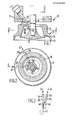
- a rotary atomizer 10 includes a housing 11, shown only partially, to the front end of which is secured an atomizing device 12.
- the device 12 consists of a mushroom-shaped boss 13 secured to the end of a shaftl4 projecting from the housing 11 and in use rotated at high speed, e.g. 30,000 r.p.m., by a motor or turbine, not shown.
- the boss 13 is unitary with a generally cup-shaped member 15, hereafter referred to as 'bell 15'.
- a row of circumferential holes 16 is formed at the junction of the radially outer edge of the head of the boss 13 and a projection on the internal wall of the bell 15.
- the downstream edge 17 of the bell 15 is a sharp discharge edge.
- the stem of the boss 13 and the internal wall of the bell 15 form an annular chamber 18.
- Into this chamber 18 extends the outlet 20 of a feed tube 21 for the liquid coating material, connected -at its other end to a source of the liquid and a pump, not shown.
- the direction of flow of the liquid along the feed tube 21 is indicated by an arrow L in Figures 2 and 3.
- an air (or other gas) supply tube 25 having an outlet 26 projects into the chamber 18 at a location radially and circumferentially spaced from tube 21.
- This tube 25 is connected in use to a source of supply delivering air at a relatively low pressure of 2-3 p.s.i. or about 14-21x10 3 pascals.
Landscapes
- Application Of Or Painting With Fluid Materials (AREA)
- Nozzles (AREA)
- Electrostatic Spraying Apparatus (AREA)
- Paints Or Removers (AREA)
Priority Applications (1)
| Application Number | Priority Date | Filing Date | Title |
|---|---|---|---|
| AT84305227T ATE40800T1 (de) | 1983-08-02 | 1984-08-01 | Drehglockenspritzvorrichtung zum duennen beschichten von werkstuecken mit fluessigkeit und verfahren zu ihrer anwendung. |
Applications Claiming Priority (2)
| Application Number | Priority Date | Filing Date | Title |
|---|---|---|---|
| GB8320827 | 1983-08-02 | ||
| GB838320827A GB8320827D0 (en) | 1983-08-02 | 1983-08-02 | Coating workpieces |
Publications (3)
| Publication Number | Publication Date |
|---|---|
| EP0133056A2 true EP0133056A2 (fr) | 1985-02-13 |
| EP0133056A3 EP0133056A3 (en) | 1985-09-25 |
| EP0133056B1 EP0133056B1 (fr) | 1989-02-15 |
Family
ID=10546681
Family Applications (1)
| Application Number | Title | Priority Date | Filing Date |
|---|---|---|---|
| EP84305227A Expired EP0133056B1 (fr) | 1983-08-02 | 1984-08-01 | Appareil de pulvérisation à cloche rotative pour l'application d'une couche mince et procédé pour son utilisation |
Country Status (6)
| Country | Link |
|---|---|
| US (1) | US4521462A (fr) |
| EP (1) | EP0133056B1 (fr) |
| JP (1) | JPS6058256A (fr) |
| AT (1) | ATE40800T1 (fr) |
| DE (1) | DE3476740D1 (fr) |
| GB (1) | GB8320827D0 (fr) |
Families Citing this family (45)
| Publication number | Priority date | Publication date | Assignee | Title |
|---|---|---|---|---|
| JPS624464A (ja) * | 1985-07-02 | 1987-01-10 | Honda Motor Co Ltd | 車体塗装装置 |
| US4721630A (en) * | 1985-07-31 | 1988-01-26 | Honda Giken Kogyo Kabushiki Kaisha | Painting process for inner panel region of motorcar vehicle body and apparatus therefor |
| US5316579A (en) * | 1988-12-27 | 1994-05-31 | Symetrix Corporation | Apparatus for forming a thin film with a mist forming means |
| JPH0651160B2 (ja) * | 1989-03-31 | 1994-07-06 | 本田技研工業株式会社 | 水性メタリック塗料の塗装方法 |
| US5156336A (en) * | 1989-12-27 | 1992-10-20 | Xerox Corporation | Multiple fluid injection nozzle array for rotary atomizer |
| US6102298A (en) * | 1998-02-23 | 2000-08-15 | The Procter & Gamble Company | Ultrasonic spray coating application system |
| JP2002503492A (ja) | 1998-02-23 | 2002-02-05 | ザ プロクター アンド ギャンブル カンパニー | 食品用オーブン仕上げシステム |
| US8141797B2 (en) * | 2001-01-25 | 2012-03-27 | Durr Systems Inc. | Rotary atomizer for particulate paints |
| US6189804B1 (en) | 1998-03-27 | 2001-02-20 | Behr Systems, Inc. | Rotary atomizer for particulate paints |
| US6344109B1 (en) | 1998-12-18 | 2002-02-05 | Bki Holding Corporation | Softened comminution pulp |
| US6641666B2 (en) | 1999-11-15 | 2003-11-04 | Ppg Industries Ohio, Inc. | Method and apparatus for coating a substrate |
| US7445816B2 (en) * | 1999-11-15 | 2008-11-04 | Ppg Industries Ohio, Inc. | Method and apparatus for coating a substrate |
| US6291018B1 (en) * | 1999-11-15 | 2001-09-18 | Ppg Industries Ohio, Inc. | Method for applying a composite coating having a polychromatic effect onto a substrate |
| AU1471801A (en) * | 1999-11-15 | 2001-05-30 | Ppg Industries Ohio, Inc. | Method and apparatus for applying a polychromatic coating onto a substrate |
| US6296706B1 (en) | 1999-11-15 | 2001-10-02 | Ppg Industries Ohio, Inc. | Method and apparatus for dynamically coating a substrate |
| DE10115467A1 (de) * | 2001-03-29 | 2002-10-02 | Duerr Systems Gmbh | Werkzeugwechselsystem für eine Maschine |
| DE10115470A1 (de) * | 2001-03-29 | 2002-10-10 | Duerr Systems Gmbh | Beschichtungsanlage mit einer Zerstäuberwechselstation |
| DE10115463A1 (de) * | 2001-03-29 | 2002-10-02 | Duerr Systems Gmbh | Zerstäuber für eine Beschichtungsanlage und Verfahren zu seiner Materialversorgung |
| DE10115472A1 (de) * | 2001-03-29 | 2002-10-10 | Duerr Systems Gmbh | Ventileinheit für eine elektrostatische Beschichtungsanlage |
| DE10139088A1 (de) * | 2001-08-16 | 2003-02-27 | Duerr Systems Gmbh | Manipulatormaschine mit einer zu dem Arbeitsgerät geführten Leitungsanordnung |
| DE10202711A1 (de) * | 2002-01-24 | 2003-07-31 | Duerr Systems Gmbh | Zerstäuber für die elektrostatische Serienbeschichtung von Werkstücken |
| KR100478608B1 (ko) * | 2002-02-26 | 2005-03-28 | 김정원 | 로타리 오토마이저 |
| DE10301942A1 (de) * | 2003-01-20 | 2004-07-29 | Dürr Systems GmbH | Hydraulisch dynamischer Monomolch |
| DE10231421A1 (de) | 2002-07-11 | 2004-01-22 | Dürr Systems GmbH | Verfahren und System zur Versorgung eines Pulverbeschichtungsgerätes |
| DE10233197A1 (de) * | 2002-07-22 | 2004-02-05 | Dürr Systems GmbH | Potentialausgleichsanordnung für einen elektrostatischen Rotationszerstäuber |
| DE10233198A1 (de) * | 2002-07-22 | 2004-02-05 | Dürr Systems GmbH | Rotationszerstäuber |
| DE10233199A1 (de) * | 2002-07-22 | 2004-02-05 | Dürr Systems GmbH | Turbinenmotor eines Rotationszerstäubers |
| DE10239516A1 (de) * | 2002-08-28 | 2004-03-18 | Dürr Systems GmbH | Schlauch für die elektrostatische Beschichtung von Werkstücken |
| DE10239517A1 (de) * | 2002-08-28 | 2004-03-11 | Dürr Systems GmbH | Beschichtungseinrichtung mit einem Rotationszerstäuber und Verfahren zum Steuern ihres Betriebes |
| DE10240072B4 (de) * | 2002-08-30 | 2005-11-24 | Dürr Systems GmbH | Molch zur Förderung eines Beschichtungsmaterials und Verfahren zu seiner Herstellung |
| DE10240451A1 (de) | 2002-09-02 | 2004-03-11 | Dürr Systems GmbH | Sensoranordnung für eine Beschichtungsanlage |
| DE10245594A1 (de) * | 2002-09-30 | 2004-04-08 | Dürr Systems GmbH | Verfahren zur Kollisionserkennung |
| US20050002742A1 (en) * | 2002-12-11 | 2005-01-06 | Martin Bachmann | Method and device for transporting powdery substances |
| US6991178B2 (en) | 2003-01-24 | 2006-01-31 | Dürr Systems, Inc. | Concentric paint atomizer shaping air rings |
| US7934665B2 (en) * | 2003-03-28 | 2011-05-03 | Ultrasonic Systems Inc. | Ultrasonic spray coating system |
| DE102004022677A1 (de) * | 2004-05-07 | 2005-11-24 | Bayer Materialscience Ag | Vorrichtung und Verfahren zur Herstellung von Sandwich-Verbundelementen |
| US20060219816A1 (en) * | 2005-04-05 | 2006-10-05 | Durr Systems | Rotary atomizer component |
| US20080184707A1 (en) * | 2006-10-27 | 2008-08-07 | Honeywell International, Inc. | Fuel manifold for combustion systems |
| US8671495B2 (en) * | 2006-11-06 | 2014-03-18 | Durr Systems, Inc. | Scraper pig |
| KR100707851B1 (ko) | 2006-11-20 | 2007-04-18 | 김정원 | 로타리 오토마이저 및 이 로타리 오토마이저의 공기베어링보호 시스템 |
| WO2008075798A1 (fr) * | 2006-12-18 | 2008-06-26 | Nokwon Engineering & Construction Co., Ltd. | Pulvérisateur centrifuge et système de protection à palier à air destiné au pulvérisateur centrifuge |
| US9272297B2 (en) * | 2008-03-04 | 2016-03-01 | Sono-Tek Corporation | Ultrasonic atomizing nozzle methods for the food industry |
| US20090297323A1 (en) * | 2008-05-30 | 2009-12-03 | Genesis Worldwide Ii, Inc. | Method and apparatus for stacking sheet materials |
| CN110496717A (zh) * | 2019-08-02 | 2019-11-26 | 靖江市鑫盛环保科技有限责任公司 | 一种磁力离心雾化器 |
| DE102021125820A1 (de) | 2021-10-05 | 2023-04-06 | Dürr Systems Ag | Glockenteller, Rotationszerstäuber mit dem Glockenteller, Lackieranlage und entsprechendes Lackierverfahren |
Citations (5)
| Publication number | Priority date | Publication date | Assignee | Title |
|---|---|---|---|---|
| BE665065A (fr) * | 1965-06-24 | |||
| US3000574A (en) * | 1959-12-08 | 1961-09-19 | Interplanetary Res & Dev Corp | Dual atomization and electrostatic deposition means |
| US4009764A (en) * | 1974-05-22 | 1977-03-01 | Hafner Henry F | Lubricating apparatus for conveyor chains |
| FR2412351A1 (fr) * | 1977-12-20 | 1979-07-20 | Air Ind | Projecteur electrostatique de peinture a bol ou a disque tournant avec un joint d'etancheite pneumatique |
| GB2086765A (en) * | 1980-11-03 | 1982-05-19 | Ransburg Corp | Rotary atomiser |
Family Cites Families (3)
| Publication number | Priority date | Publication date | Assignee | Title |
|---|---|---|---|---|
| US3001890A (en) * | 1956-07-27 | 1961-09-26 | Interplanetary Res & Dev Corp | Electrostatic deposition |
| US3221992A (en) * | 1962-02-08 | 1965-12-07 | Jr John Sedlacsik | Coating material motive agent atomizer head |
| US4337895A (en) * | 1980-03-17 | 1982-07-06 | Thomas Gallen | High speed rotary atomizers |
-
1983
- 1983-08-02 GB GB838320827A patent/GB8320827D0/en active Pending
-
1984
- 1984-07-30 US US06/635,619 patent/US4521462A/en not_active Expired - Lifetime
- 1984-07-31 JP JP59159484A patent/JPS6058256A/ja active Granted
- 1984-08-01 EP EP84305227A patent/EP0133056B1/fr not_active Expired
- 1984-08-01 DE DE8484305227T patent/DE3476740D1/de not_active Expired
- 1984-08-01 AT AT84305227T patent/ATE40800T1/de not_active IP Right Cessation
Patent Citations (5)
| Publication number | Priority date | Publication date | Assignee | Title |
|---|---|---|---|---|
| US3000574A (en) * | 1959-12-08 | 1961-09-19 | Interplanetary Res & Dev Corp | Dual atomization and electrostatic deposition means |
| BE665065A (fr) * | 1965-06-24 | |||
| US4009764A (en) * | 1974-05-22 | 1977-03-01 | Hafner Henry F | Lubricating apparatus for conveyor chains |
| FR2412351A1 (fr) * | 1977-12-20 | 1979-07-20 | Air Ind | Projecteur electrostatique de peinture a bol ou a disque tournant avec un joint d'etancheite pneumatique |
| GB2086765A (en) * | 1980-11-03 | 1982-05-19 | Ransburg Corp | Rotary atomiser |
Also Published As
| Publication number | Publication date |
|---|---|
| JPS6058256A (ja) | 1985-04-04 |
| US4521462A (en) | 1985-06-04 |
| DE3476740D1 (en) | 1989-03-23 |
| EP0133056A3 (en) | 1985-09-25 |
| GB8320827D0 (en) | 1983-09-01 |
| JPH0421550B2 (fr) | 1992-04-10 |
| ATE40800T1 (de) | 1989-03-15 |
| EP0133056B1 (fr) | 1989-02-15 |
Similar Documents
| Publication | Publication Date | Title |
|---|---|---|
| EP0133056B1 (fr) | Appareil de pulvérisation à cloche rotative pour l'application d'une couche mince et procédé pour son utilisation | |
| CA2041512C (fr) | Coupelle rotative | |
| US4919333A (en) | Rotary paint atomizing device | |
| JP3445282B2 (ja) | エアゾル生成装置 | |
| EP2195055B1 (fr) | Buse d'atomisation ultrasonore avec particularité de pulvérisation par ventilateur variable | |
| JPH0356102B2 (fr) | ||
| JP3473718B2 (ja) | 回転霧化静電塗装方法および装置 | |
| CN113164994B (zh) | 用于喷涂涂覆产品的碗状物,包括该碗状物的旋转式喷涂设备以及该喷涂设备的清洁方法 | |
| US5800867A (en) | Deflection control of liquid or powder stream during dispensing | |
| EP3938115B1 (fr) | Pulvérisateur à bol rotatif muni d'une turbine auxiliaire et d'un générateur d'air de vortex | |
| JP3837600B2 (ja) | スパイラルスプレー塗布方法およびスパイラルスプレー塗布装置 | |
| JP3248340B2 (ja) | 回転霧化静電塗装方法およびその装置 | |
| JP2000351090A (ja) | レーザ溶射用ノズル | |
| RU2311964C1 (ru) | Распылитель жидкости | |
| JPH0137716Y2 (fr) | ||
| US6857581B2 (en) | Spraying method and a spray system for coating liquids | |
| JPS58124560A (ja) | 静電塗装装置 | |
| JPS6146272A (ja) | 静電塗装装置 | |
| JPH07163918A (ja) | 噴霧方法および噴霧器 | |
| JPH08294647A (ja) | 回転霧化塗装装置 | |
| SU1337142A1 (ru) | Распылитель жидкости | |
| JPH05317758A (ja) | 霧化装置 | |
| JPS6239016B2 (fr) | ||
| JPS634518Y2 (fr) | ||
| JPH1099736A (ja) | ベル型塗装装置およびベル型塗装装置を用いた塗装方法 |
Legal Events
| Date | Code | Title | Description |
|---|---|---|---|
| PUAI | Public reference made under article 153(3) epc to a published international application that has entered the european phase |
Free format text: ORIGINAL CODE: 0009012 |
|
| AK | Designated contracting states |
Designated state(s): AT BE CH DE FR GB IT LI LU NL SE |
|
| PUAL | Search report despatched |
Free format text: ORIGINAL CODE: 0009013 |
|
| AK | Designated contracting states |
Designated state(s): AT BE CH DE FR GB IT LI LU NL SE |
|
| 17P | Request for examination filed |
Effective date: 19860214 |
|
| 17Q | First examination report despatched |
Effective date: 19861022 |
|
| D17Q | First examination report despatched (deleted) | ||
| GRAA | (expected) grant |
Free format text: ORIGINAL CODE: 0009210 |
|
| AK | Designated contracting states |
Kind code of ref document: B1 Designated state(s): AT BE CH DE FR GB IT LI LU NL SE |
|
| PG25 | Lapsed in a contracting state [announced via postgrant information from national office to epo] |
Ref country code: SE Effective date: 19890215 Ref country code: LI Effective date: 19890215 Ref country code: IT Free format text: LAPSE BECAUSE OF FAILURE TO SUBMIT A TRANSLATION OF THE DESCRIPTION OR TO PAY THE FEE WITHIN THE PRESCRIBED TIME-LIMIT;WARNING: LAPSES OF ITALIAN PATENTS WITH EFFECTIVE DATE BEFORE 2007 MAY HAVE OCCURRED AT ANY TIME BEFORE 2007. THE CORRECT EFFECTIVE DATE MAY BE DIFFERENT FROM THE ONE RECORDED. Effective date: 19890215 Ref country code: FR Free format text: THE PATENT HAS BEEN ANNULLED BY A DECISION OF A NATIONAL AUTHORITY Effective date: 19890215 Ref country code: CH Effective date: 19890215 Ref country code: BE Effective date: 19890215 |
|
| REF | Corresponds to: |
Ref document number: 40800 Country of ref document: AT Date of ref document: 19890315 Kind code of ref document: T |
|
| REF | Corresponds to: |
Ref document number: 3476740 Country of ref document: DE Date of ref document: 19890323 |
|
| REG | Reference to a national code |
Ref country code: CH Ref legal event code: PL |
|
| EN | Fr: translation not filed | ||
| PG25 | Lapsed in a contracting state [announced via postgrant information from national office to epo] |
Ref country code: LU Free format text: LAPSE BECAUSE OF NON-PAYMENT OF DUE FEES Effective date: 19890831 |
|
| PLBE | No opposition filed within time limit |
Free format text: ORIGINAL CODE: 0009261 |
|
| STAA | Information on the status of an ep patent application or granted ep patent |
Free format text: STATUS: NO OPPOSITION FILED WITHIN TIME LIMIT |
|
| 26N | No opposition filed | ||
| NLS | Nl: assignments of ep-patents |
Owner name: GFG CORPORATION TE MILWAUKEE, WISCONSIN, VER. ST. |
|
| REG | Reference to a national code |
Ref country code: GB Ref legal event code: 732E |
|
| PGFP | Annual fee paid to national office [announced via postgrant information from national office to epo] |
Ref country code: GB Payment date: 19970514 Year of fee payment: 14 |
|
| PG25 | Lapsed in a contracting state [announced via postgrant information from national office to epo] |
Ref country code: GB Free format text: LAPSE BECAUSE OF NON-PAYMENT OF DUE FEES Effective date: 19980801 |
|
| PGFP | Annual fee paid to national office [announced via postgrant information from national office to epo] |
Ref country code: AT Payment date: 19990226 Year of fee payment: 15 |
|
| PGFP | Annual fee paid to national office [announced via postgrant information from national office to epo] |
Ref country code: NL Payment date: 19990228 Year of fee payment: 15 |
|
| GBPC | Gb: european patent ceased through non-payment of renewal fee |
Effective date: 19980801 |
|
| PGFP | Annual fee paid to national office [announced via postgrant information from national office to epo] |
Ref country code: DE Payment date: 19990331 Year of fee payment: 15 |
|
| PG25 | Lapsed in a contracting state [announced via postgrant information from national office to epo] |
Ref country code: AT Free format text: LAPSE BECAUSE OF NON-PAYMENT OF DUE FEES Effective date: 19990801 |
|
| PG25 | Lapsed in a contracting state [announced via postgrant information from national office to epo] |
Ref country code: NL Free format text: LAPSE BECAUSE OF NON-PAYMENT OF DUE FEES Effective date: 20000301 |
|
| NLV4 | Nl: lapsed or anulled due to non-payment of the annual fee |
Effective date: 20000301 |
|
| PG25 | Lapsed in a contracting state [announced via postgrant information from national office to epo] |
Ref country code: DE Free format text: LAPSE BECAUSE OF NON-PAYMENT OF DUE FEES Effective date: 20000601 |