EP0128491B1 - Contrôleur adaptatif commutant en-hors à des instants discrets - Google Patents
Contrôleur adaptatif commutant en-hors à des instants discrets Download PDFInfo
- Publication number
- EP0128491B1 EP0128491B1 EP84106304A EP84106304A EP0128491B1 EP 0128491 B1 EP0128491 B1 EP 0128491B1 EP 84106304 A EP84106304 A EP 84106304A EP 84106304 A EP84106304 A EP 84106304A EP 0128491 B1 EP0128491 B1 EP 0128491B1
- Authority
- EP
- European Patent Office
- Prior art keywords
- prediction
- time
- switching
- sequence
- output
- Prior art date
- Legal status (The legal status is an assumption and is not a legal conclusion. Google has not performed a legal analysis and makes no representation as to the accuracy of the status listed.)
- Expired
Links
Images


Classifications
-
- G—PHYSICS
- G05—CONTROLLING; REGULATING
- G05B—CONTROL OR REGULATING SYSTEMS IN GENERAL; FUNCTIONAL ELEMENTS OF SUCH SYSTEMS; MONITORING OR TESTING ARRANGEMENTS FOR SUCH SYSTEMS OR ELEMENTS
- G05B13/00—Adaptive control systems, i.e. systems automatically adjusting themselves to have a performance which is optimum according to some preassigned criterion
- G05B13/02—Adaptive control systems, i.e. systems automatically adjusting themselves to have a performance which is optimum according to some preassigned criterion electric
- G05B13/04—Adaptive control systems, i.e. systems automatically adjusting themselves to have a performance which is optimum according to some preassigned criterion electric involving the use of models or simulators
- G05B13/048—Adaptive control systems, i.e. systems automatically adjusting themselves to have a performance which is optimum according to some preassigned criterion electric involving the use of models or simulators using a predictor
Definitions
- the present invention relates to an arrangement and a method for the predictive discrete-time adaptive on-off control of continuous-time processes with binary switching actuators.
- Controllers with binary switching actuators excel in their reliability and robustness. Parameter adjustment of conventional switching on-off controllers is based on the results of empirical investigations on standardized model processes specified by simple parameters. Due to the non-linearity of the controller an analytical determination of its parameters for an optimal control in the sense of an optimization criterion can be done only with very high effort.
- the object of the invention is to enable even unskilled personnel to operate it and to avoid overshooting to a great extent in the start-up phase of the process or after setpoint changes without making the additional technical effort which has been required.
- the switching between the said control means is advantageously used to activate the first control means which is especially suited to control disturbances or to follow changes of the process dynamics in the steady state phase of the process or the second control means which is especially suited to approach the desired setpoint without overshooting and simultaneously estimate the process dynamics in the new operating point at the start of the process or after a set-point change, respectively.
- control means for the transient phase i.e. for the control at the start of the process and after setpoint changes, is activated when the arrangement is turned on to start the process or if a new setpoint is given in, and the first control means for the stationary phase is activated when in the transient phase the measured process output reaches a prefixed distance from the setpoint for the first time.
- the parameter estimation means which works according to the known Least-Squares method with U-D-factorization, may yield the current values of the estimated process parameters and the process output values measured currently or at previous instants and the process input values determined currently or at previous instants, which are necessary for the prediction of process output sequences, and send them as process model to the active control means.
- the application of the above-mentioned estimation method is useful, as, contrary to the methods applied up to now, it can easily realize fast working numerical stable parameter estimation means.
- the same process model can be used for the prediction in the same way by both control means, so that a reduction of the technical effort is possible.
- the prediction of the 2 r possible process output sequences over r prediction steps within the first control means for the steady state phase can be performed in the following way.
- the 2 r process output sequences are successively predicted, as responses of the process model to the 2 r process input sequences being different from each other.
- each of the process input sequences for the current predictions of the process output sequence is such that it has as many as possible switching levels in common with ones of the previously used process input sequence within the nearer future prediction steps and only the switching levels of each of the process input sequences within the farther future prediction steps are changed.
- the corresponding values within the process output sequence are predicted only with respect to the switching levels thus changed. This is advantageous in so far as the information gained about possible future process output sequences can be reused during the successive prediction.
- the technical effort and the necessary time for processing the prediction within the first control means can be reduced.
- each prediction step of the prediction within the first control means for the stationary phase can be divided into several sampling intervals, with the switching levels in the sampling intervals of each prediction step remaining equal. This is advantageous as with constant prediction time the sampling time and thus the quantization of actuating power can be reduced and thereby the necessary processing time only grows linearly and not any longer exponentially with the ratio, prediction time vs. sampling time.
- the determination of the evaluation parameter (cost-function) of each predicted process output sequence is made in the known way directly with the prediction of the corresponding process output sequence.
- the actuating signal to be given out in the next sampling interval may be selected in process input selection means by comparison of the evaluation parameter of the just predicted process output sequence with that of the process output sequence predicted before.
- the number of process input sequences that have to be considered for a prediction of possible future process output sequences is smaller than 2 r . It is the aim of the control action in the transient phases of the process to bring the process output near to the setpoint as fast as possible in order to approach the setpoint with the process output with the least overshooting by switching the actuating signal to its counteracting level early enough. It is an advantage that during the transient phases of the process only the prediction of one single process output sequence is necessary.
- the second control means which is active at the start of the process or after setpoint changes is designed in such a way that the extremal point of the future process output sequence is predicted on the basis of one particular process input sequence, which provides only such one single switching of the actuating signal, that is made after the first sampling interval within that process input sequence.
- the second control means active at the start of the process or after a setpoint change uses a number of predictions of possible future process output sequences that is smaller than that of the ones used by the first control means active for the stationary phase.
- the thus saved processing time is advantageously used in such a way that predicting means within the second control means is enabled to make a prediction of the mentioned single process output sequence which reaches further into the future.
- a superior limit supervisory control means is applied in such a way that if the process output exceeds its preset upper or lower limit, respectively, the just active the first or the second control means is turned off and the actuating signal of the process is switched Off or On, respectively.
- limit supervisory control means which can be activated manually, is applied for the control of the process.
- the process is excited by means of the actuator in such a way that the process output periodically moves within a range of preset upper and lower limits.
- This oscillation which in general is comparatively stronger than the limit cycle in the stationary phase can advantageously be used to determine a process model which matches as well as possible with the real process.
- predicting means within the first or second control means can thus rely on a useful process model from the very beginning of the control phase.
- the actuator for the output of the actuating signal is driven synchronously with the same tact rate, as the measuring device for the acquisition of the process output.
- the discrete-time adaptive on-off switching control consists of the two components, i.e. parameter estimation and predictive switching on-off control.
- the predictive switching on-off control can be divided into the prediction of process output and the determination of the optimal on-off actuating signal.
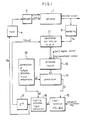
- Fig. 1 shows the structure of this concept (especially that of control in steady state phase).
- the process 1 is, for example, a furnace provided with an electric heater.
- heating electric current being fed to the heater process input is heating electric current.
- the heating electric current fed to the heater is on-off controlled by means of an actuator 2, for example, a relay.
- the temperature of the furnace is measured at predetermined sampling intervals T by a sampling device 3.
- the process output is temperature.
- the process output Y(k) measured at equidistant time instants and the process input U(k) actually applied to the process 1 are used.
- Eqn. (1) from these values Y(k) and U(k) the d.c.-values Y o and U o , respectively, are subtracted.
- This process. model 12 is represented by Eqn. (2). wherein 6 means transfer function of the process and z -d , deadtime element, ⁇ (z -1 ) and ⁇ (z -1 ) being each given by the following Eqns. with the sign "'" denoting estimated value, wherein â 1 , ..., â n and , ..., are parameters to be estimated.
- the model order n as well as the number of deadtime steps d have to be chosen suitably depending on the process to be controlled.
- the process input u i is a value estimated and actually given to the process, it is delayed by deadtime steps d by means of a deadtime element 17.
- the process output y is a value taken out by the sampling device 3.
- the process input u, and the process output y, to describe the model 12 at time k ⁇ T are indicated on time axis.
- the thus gained process model 12 is used in the predictive on-off switching control to determine the on-off process input to be applied to the process 1 at the next sampling interval from the view-point of a chosen costfunction 15 (in the case of multi-step optimization, namely stead state phase).
- future process output sequences Y are predicted (block 14).
- These output sequences Y i are response of the process model 12 to the future process input sequences U, generated in the block 13.
- these process output sequences Y are sequences which would be possible within a prediction time Tp ahead of the deadtime d ⁇ T.
- the predicted process output sequences Y are evaluated by a costfunction 15.
- the process input sequence is said to be optimal when the costfunction comes to minimum value owing to the corresponding process output.
- the first element of the process input sequence thus determined to be optimal (block 16) is used to switch on or off the actuator 2 of the process 1 at the next sampling interval.
- the prediction over the prediction time Tp is made by dividing this Tp into a certain suitable number of r prediction steps, each prediction step consisting of q sampling intervals, within which the process input u is assumed to have the same constant value.
- the prediction time Tp is given by the following Eqn:
- sampling interval T can be optionally fixed irrespective of the prediction time Tp or the number of prediction steps r.
- control task The answer to the question as to which of the 2 r process input sequences are considered for prediction and evaluation, depends on the control task. There are following two cases of control task:
- the control is made via the "transient phase control". Only one process input sequence is used for prediction here. In either case, according to the process output sequence predicted it is decided whether the actual value of the process input to be applied to the process 1 is kept constant at the next sampling instant or has to be switched to its counteracting level.
- the decision as to which of the two switching controls is to be applied at the moment depends on the setpoint and the process output sequence.
- the change-over from the stationary phase control to the transient phase control is made, e.g., after a setpoint change has occurred.
- the change-over from the transient phase control to the stationary phase control happens, e.g., when the absolute value of the deviation (difference between setpoint w and the measured process output y)
- the stationary phase control is not used until the transient phase is settled to a full extent.
- the Recursive Least Squares estimation is a suitable parameter estimation method within the adaptive on-off switching controller. This method is applicable to any processes, and further according to this method computer load can be reduced.
- the aim of the parameter estimation is to determine the parameters â i and of the process model (see Eqn. (2) and (3)) at any sampling instant k . T from the acquired values y(k) and u(k). This aim is realized by minimizing the so-called equation error (Eqn. (7)) of the loss function (Eqn. (8)).
- the recursive estimation of the parameter vector 6 is performed by adding a correction term, the product of the equation error e(k) and a correction vector g(k) (Eqn. (10)), to the latest actual parameter vector 6(k-1).
- the recursive estimation equation is given as
- the correction vector g(k) (Eqn. (10)) includes the scalar (Eqn. (11)) and the normalized covariance matrix of the parameter error (Eqn. (12)).
- the adaption factor p in Eqns. (11) and (12) means the weight of data. Owing to this p a higher evaluation is given to the present data than to the past data. The choice of p ⁇ 1 causes a greater change of parameters, which results in giving a greater margin for parameter changes and allowing an easier tracking of time-variant processes.
- the possibility to estimate the process parameters with a sufficient exactness depends, among others, on the numerical data processing on a digital computer.
- the word length L (in Bit) of the internal arithmetical data representation has an influence on the parameter accuracy.
- Possibilities to avoid these problems are given by the U-D-Factorization. This method was proposed by Bierman: Measurement Updating using the U-D-Factorization. Automatica, Vol. 12, pp. 375-382, Pergamon Press, 1976.
- This method is based on the calculation of the covariance matrix as matrix product
- U(k) is an upper triangular matrix
- D(k) is a diagonal matrix and can be stored in vector form.
- the predictive on-off switching control (1) The stationary phase control
- the two process inputs u max and u min correspond to 1 (H level) and 0 (L level), respectively when represented in terms of the switching levels of the actuator 2. More specifically, when the actuator 2 is on, the process input u max is given to the process 1 and when it is off, u min is applied thereto.
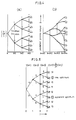
- all the process input sequences are represented in terms of the switching levels of the actuator 2 as follows:
- the process input sequences U 1 , ..., U4 each have a common value 1 (u max ) at (k+1) and different values at (k+2) and (k+3).
- u max a common value 1
- U 1 and U 2 it will be noticed that each of these sequences has a common value 1 at (k+ 1) and (k+2) and different values merely at (k+3).
- 2 P of the 2 r process input sequences which differ from each other only within the last p prediction steps. All the process output sequences are predicted by making use of such fact.
- the prediction of the process output is performed by calculating with use of the estimated values, as shown by the following equations,
- the signal vector x T (k+2) is acquired by substituting k with (k+ 1) in Eqn. (5). This substitution is equivalent to newly introducing y(k+1) and u(k-d+1) as the values in the first and the (n+1)th rows respectively, shifting the values in other rows to the following rows successively and further removing the values in the nth and the 2nth rows, in the signal vector x T (k+1) of Eqn. (5).
- y(k+1) is the predicted value derived from Eqn. 17.
- the other values y(k), ..., y(k-n+2) and u(k-d+1), ..., u(k-d-n+2) are known ones.
- the signal vector is successively derived from the signal vector by updating the first and the (n+1)th elements with y(k+j) and u(k-d+j), respectively.
- y(k+j) and u(k-d+j) are known values and with (k-d+j) ⁇ (k+1), possible values are adopted as u(k-d+j).
- the necessary setpoints are incorporated in the setpoint vector for the comparison with the process output sequence vector Y i .
- the setpoint vector is represented by
- the multi-step-costfunction thus reads:
- integral criteria are often used as costfunctions, wherein the difference between the process output and the setpoint is suitably weighted and when its value has become minimum, the process output is evaluated to the optimal. Accordingly the predictions in the adaptive on-off switching controller are evaluated by discrete-time approximations of the following integral criteria with
- the evaluation of the predictions over r prediction steps by a multi-step-costfunction J is equal to the sum of the one-step-costfunction.l:
- Fig. 5 depicts the results of the optimization procedure.
- the 2 r (r 3) process input sequences U i (see Fig. 4) and output sequences, respectively, correspond to the 2 r branches of the tree.
- I(k+1) the values of the multi-step-costfunction
- J multi-step-costfunction
- the process input sequence U 2 producing 9 is considered to be the real optimum.
- the one-step-optimization leads a slightly inferior control when compared with the multi-step-optimization.
- Fig. 6 For the prediction and evaluation of process output sequences in the transient phase, the number of the process input sequences to be investigated can be reduced. How the transient phase control is performed is shown by Fig. 6, in which (a) is the continuous-time case and (b), the discrete-time case. In the continuous-time case (Fig. 6(a)), it is assumed that at a time to the setpoint has been changed from w, to w 2 . The process output y(t) is approaching this new setpoint w 2 as the time goes by.
- the time interval (t 1 -t o ) can be approximated with a sufficient accuracy by an interval (k 1 -k o ) ⁇ T, when T is sufficiently small. So the above-mentioned response of the process output (see Eqns. (26) and (27)) can be realized in such an exact way also in the discrete-time control.
- the dot-and-dash line shows the process output y(k) predicted within the prediction time starting from a time (k1 1 -2).
- This process output y(k) is that which is predicted based on such a process input (indicated by the dot-and-dash line) as will be switched once to its counteracting level after the next sampling interval.
- the process output and the process input shown by the solid lines in Fig. 6(b) indicate the values predicted within the prediction time starting from a time (k 1 -1). Since the transient phase control is a control performed within a period until the predicted future process output y(k) reaches a new setpoint w 2 , for the prediction it is sufficient to determine only the position of the extremal point y ex (max. value or min. value) of the process output.
- a determination of u(k+1) is allowed even in the case where no real extremal point but only a local extremal point at the end of the prediction time could be predicted.
- the prediction of the process output sequence as response of the process model to the process input sequence given in Eqns. (28) and (29) is performed in the same way as with the stationary phase control.
- the required computing time is far shorter than that for the stationary phase control under the assumption of equal prediction time Tp.
- the number r of the prediction steps in the stationary phase control is 3, with the same computing time, the number r tr of the prediction steps in the transient phase really comes to 14. In this way, during the transient phase the prediction time Tp can be lengthened enough to find the optimal sampling interval for switching sufficiently early.
- the calculation for the prediction is carried out by means of a micro computer, it takes quite a long time, so that the number r of the prediction steps cannot be enlarged too much.
- the above-mentioned transient phase control allows to make this number r of the prediction steps sufficiently large, so that it is possible to avoid the overshooting of the process output even if the process responds quickly.
- the adaptive on-off switching controller is arranged to be supplied with initial values of the parameters from the outside.
- the adaptive on-off switching controller is provided with a limit supervisory control, which allows to switch the process input off or on in the next sampling interval when the process output exceeds the upper limit Y max or drops below the lower limit Y min .
- the exceeding of the limits is indicated via an alarm line.
- the adaptive on-off switching controller is disconnected until it is set in operation again.
- the predictive on-off switching control in order to excite the process by a defined binary test signal.
- This may be useful for parameter estimation without closed loop adaptive on-off switching control.
- the actuating signal is switched on by the test signal until the process output exceeds the upper limit Y maX . It is then switched off by the test signal until the process output drops below the lower limit Y min . Then the process input is switched on again and the described procedure is repeated.
- Y max and Y min a process model can be estimated which is valid for a certain vicinity of the desired operating point.
- the predictive on-off switching control can be set in operation again by using the estimated process model as initial data.
- the data acquisition of the process output is carried out via a device, by which analogue continuous-time process output signals Y(t) can be measured at equidistant time intervals T as discrete-time values Y(k) and are converted to a digital number representation.
- This representation is then transferred to the micro computer system in order to estimate the actual process model and to determine the optimal process input by use of the predictive on-off switching control for the next sampling instant.
- the actual process output Y(k) is compared with the control limits Y max and Y min . If Y(k) lies within the above-mentioned limits, the determined optimal process input U(k+1) is stored.
- the process input is determined to be on or off and stored by the limit supervisory control as described above.
- the stored process input is sent to the actuator (e.g. a relay) via a hold element (Fig. 1, block 4) at the next sampling instant.
- the computer-internal representation of this process input U(k+1 ) is thus converted to a physical signal (e.g. a TTL-voltage) to drive the actuator of the process.
- the discrete-time adaptive predictive on-off switching controller is realized by a programmed computer or hardware circuits.
- a limit supervisory control device 52 for the control of the process can be activated and the parameter estimation can be made by the control device 52, if it is provided with no adaptive control device data input, e.g., initial values of estimation parameters of the process model or a signal for manually operating the control device 52.
- the setpoint is transmitted as discrete-time value w to a switching device 53 and to a stationary phase control device 30 and a transient phase control device 40, these control devices 30 and 40 being activated via a switch 55.
- the two limits of the process output are transmitted to the limit supervisory control device 52 as signals Y max and Y min .
- This device 52 is activated based on the adaptive control device data input or when the process output exceeds the limits.
- the parameters of a discrete-time linear model estimated by a parameter estimation device 63 are sent as a parameter sequence 6 to a predictor over the process deadtime 54 and to the predictors over the prediction time 34 and 44, respectively, of the momentarily active control device 30 or 40.
- the values of the process output and input which are necessary for the prediction are transmitted as signal sequence x to the predictor over the process deadtime 54, the limit supervisory control device 52 and the switching device 53.
- the two latter mentioned devices 52 and 53 use only the actual value of the process output y out of the sequence x.
- a prediction of future values of the process output over the process deadtime is carried out with the predictor over the process deadtime 54, the process deadtime being realised by d sampling steps as multiples of the sampling time T.
- the first d predicted values x ⁇ (k+2), ..., x ⁇ (k+d+1) are transmitted as signal sequence x ⁇ and the last predicted value y(k+d+1) of the process output y is transmitted respectively from the predictor 54. See Eqns. (17) and (18).
- the stationary phase control device 30 is activated in the depicted position of the switches 55 and 56.
- this control device 30 an impulse is sent from an increment counter 31 to a generator of the process input sequences 32, which generates one of the 2 r process input sequences U from the previously used one and sends it as signal sequence to a comparator of the process input sequences 33.
- the comparator 33 finds out how many of the switching levels of the generated process input sequence U are not equal to the corresponding ones of the previously generated sequence and sends this number p and the process input sequence U to the predictor over the prediction time 34.
- the future values of the process output are predicted on the basis of the estimated parameters 8, the signal sequence x ⁇ and the process output value y which are transmitted from the parameter estimation device 63 and the predictor 54 to the predictor 34 and, together with the (r-p) already determined values of the process output, are transmitted as process output sequence Y to an evaluation device 37.
- the setpoint sequence W which is generated in a setpoint register 36 in vector form by updating with the setpoint w input and which is transmitted to the evaluation device 37, Y is evaluated in the evaluation device 37.
- the evaluation parameter (cost-function) J calculated in the device 37 is sent to a process input selection device 35, in which the value J is compared with the last value of J. In this way, the minimum value of J is found out. If the current value J is smaller than the last stored one, the switching level for the next sampling interval, which corresponds to u(k+1), is taken from the corresponding process input sequence U stored in the device 35 and made outputtable from the device 35, otherwise the switching level which has at last been output is maintained. An impulse is then sent to the increment counter 31, the index is incremented, and sent to the generator 32 is an impulse which repeats the run of operation described above. This procedure is repeated until the increment counter 31 has incremented 2 r- times. After the 2 r th increment the increment counter 31 is reset and the switch 38 is closed, so that the switching level output from the device 35 is sent to and available at an actuator 61 where it can be taken over as actuating signal at the next sampling interval.
- the transient phase control device 40 is activated. Alike to the control device 30, the signal sequencer, the value of the process output y and the parameter sequencer are sent to the predictor over the prediction time 44.
- the setpoint w is sent to a generator of the process input sequence 42. Depending on whether the setpoint change is positive or negative this generator 42 generates a process input sequence U which contains in its first sampling interval the switching level On and in other sampling intervals the switching level Off or is established from the corresponding inverse switching levels, respectively.
- This process input sequence U is transmitted to the predictor 44, where the process output sequence as reaction to this process input sequence U is predicted over the whole prefixed prediction time.
- the extremal point of the process output y ex is determined simultaneously, which extremal point is sent to an evaluation device 47, together with the setpoint w.
- the evaluation device 47 determines now the system (setpoint) deviation Yd in the extremal point of the process output Yex and sends it to a process input selection device 45. From the process input sequence U transmitted to the device 45 the switching level of its first sampling interval is taken and given out if no overshooting is expected according to the system deviation Yd , otherwise such switching level is given out that results from changing of the above switching level to its counteracting level. No repetition of this procedure is necessary here, contrary to the operation of the stationary phase control device 30. The switching level given out from the device 45 is then available at the actuator 61 for the next sampling interval.
- the switching device 53 activates the control device 40 by means of the switches 55 and 56, if the setpoint w input is changed. It activates the control device 30 by means of the switches 55 and 56, when the distance between setpoint w and measured value y in the signal sequence x is smaller or equal to a prefixed distance during the transient phase control of the process by means of the control device 40.
- the limit supervisory control device 52 turns off the active control device 30 or 40 by means of a switch 57 by interrupting the connection between the control device 30 or 40 and the actuator 61 and itself gives the switching level for the next sampling interval, if the process output from the signal sequence x exceeds the limit Y max or Y min or if it is activated by an impulse due to a manual operation.
- a signal which corresponds to the sampling time T is sent to the actuator 61 and a measuring device 62 respectively, which use this signal for a synchronous, discrete-time output of the binary actuating signal On or Off to the process 60 and the acquisition of the measurable process output.
- the actuating signal and the process output available at the sampling instants at the actuator 61 and the measuring device 62, respectively, are transmitted as discrete-time values to the parameter estimation device 63, where the signal sequence x and the parameter sequence 6 are determined on the basis of the above mentioned estimation method for the following processing by the control device 30 or 40.
- this discrete-time adaptive on-off switching controller can be carried out by programmed computer, especially micro computer.
Claims (13)
Priority Applications (1)
| Application Number | Priority Date | Filing Date | Title |
|---|---|---|---|
| AT84106304T ATE48709T1 (de) | 1983-06-03 | 1984-06-01 | Zeitdiskret selbstanpassender ein/ausschaltregler. |
Applications Claiming Priority (2)
| Application Number | Priority Date | Filing Date | Title |
|---|---|---|---|
| DE3320224 | 1983-06-03 | ||
| DE3320224 | 1983-06-03 |
Publications (3)
| Publication Number | Publication Date |
|---|---|
| EP0128491A2 EP0128491A2 (fr) | 1984-12-19 |
| EP0128491A3 EP0128491A3 (en) | 1985-01-30 |
| EP0128491B1 true EP0128491B1 (fr) | 1989-12-13 |
Family
ID=6200647
Family Applications (1)
| Application Number | Title | Priority Date | Filing Date |
|---|---|---|---|
| EP84106304A Expired EP0128491B1 (fr) | 1983-06-03 | 1984-06-01 | Contrôleur adaptatif commutant en-hors à des instants discrets |
Country Status (8)
| Country | Link |
|---|---|
| US (1) | US4639853A (fr) |
| EP (1) | EP0128491B1 (fr) |
| JP (1) | JPH0668691B2 (fr) |
| KR (1) | KR890003114B1 (fr) |
| AT (1) | ATE48709T1 (fr) |
| AU (1) | AU554017B2 (fr) |
| BR (1) | BR8402695A (fr) |
| CA (1) | CA1208341A (fr) |
Cited By (1)
| Publication number | Priority date | Publication date | Assignee | Title |
|---|---|---|---|---|
| EP0455938B1 (fr) * | 1990-05-11 | 1994-11-30 | Landis & Gyr Technology Innovation AG | Régulateur tout-ou-rien adaptatif |
Families Citing this family (58)
| Publication number | Priority date | Publication date | Assignee | Title |
|---|---|---|---|---|
| US4773028A (en) * | 1984-10-01 | 1988-09-20 | Tektronix, Inc. | Method and apparatus for improved monitoring and detection of improper device operation |
| NO166821C (no) * | 1985-02-21 | 1991-09-04 | Aardal & Sunndal Verk As | Fremgangsmaate for styring av aluminiumoksyd-tilfoerselen til elektrolyseovner for fremstilling av aluminium. |
| FR2579784B1 (fr) * | 1985-03-26 | 1987-06-19 | Produits Ind Cie Fse | Procede et installation permettant, d'une part, de connaitre d'avance a un instant donne le resultat auquel conduit necessairement un milieu chimique evolutif donne et, d'autre part, d'assurer la regulation de ce milieu pour parvenir a un resultat determine fixe a l'avance |
| JPS61243505A (ja) * | 1985-04-19 | 1986-10-29 | Omron Tateisi Electronics Co | 離散時間制御装置 |
| JPS6310201A (ja) * | 1986-07-01 | 1988-01-16 | Omron Tateisi Electronics Co | 離散時間制御装置 |
| US4736316A (en) * | 1986-08-06 | 1988-04-05 | Chevron Research Company | Minimum time, optimizing and stabilizing multivariable control method and system using a constraint associated control code |
| US4881172A (en) * | 1986-12-22 | 1989-11-14 | Lord Corporation | Observer control means for suspension systems or the like |
| EP0291553B1 (fr) * | 1987-05-21 | 1991-07-10 | Carl Schenck Ag | Méthode pour régler une balance de dosage différentielle, en particulier pour matériaux en vrac, et une balance de dosage différentielle pour l'application de la méthode |
| US4814968A (en) * | 1987-10-19 | 1989-03-21 | Fischer & Porter Company | Self-tuning process controller |
| GB8727602D0 (en) * | 1987-11-25 | 1987-12-31 | Nat Res Dev | Industrial control systems |
| JPH01213701A (ja) * | 1988-02-20 | 1989-08-28 | Mitsuhiko Araki | 自己増殖型制御装置および同型制御方法,ならびに同制御装置で使用される増殖型コントローラ,その動作方法,その制御方法およびスーパーバイザ |
| US4916635A (en) * | 1988-09-12 | 1990-04-10 | Massachusetts Institute Of Technology | Shaping command inputs to minimize unwanted dynamics |
| US4970638A (en) * | 1988-10-31 | 1990-11-13 | The United States Of America As Represented By The Secretary Of The Air Force | Control of unknown systems via deconvolution |
| JP2553675B2 (ja) * | 1988-11-18 | 1996-11-13 | 日本電気硝子株式会社 | プロセスの制御方法 |
| US4959767A (en) * | 1988-11-23 | 1990-09-25 | Elsag International B.V. | Parameter estimation technique for closed loop system |
| DE3839675C2 (de) * | 1988-11-24 | 1996-02-15 | Lawrenz Wolfhard | Optimierer für ein parameterabhängiges Steuerungssystem |
| WO1990015369A1 (fr) * | 1989-06-05 | 1990-12-13 | The University Of Newcastle Research Associates Limited | Controleur pour un systeme |
| EP0439091B1 (fr) * | 1990-01-22 | 1995-10-04 | Matsushita Electric Industrial Co., Ltd. | Système de commande adaptative |
| US5442544A (en) * | 1990-01-26 | 1995-08-15 | Honeywell Inc. | Single input single output rate optimal controller |
| ATE143509T1 (de) * | 1990-06-21 | 1996-10-15 | Honeywell Inc | Auf variablem horizont basierende adaptive steuerung mit mitteln zur minimierung der betriebskosten |
| JPH0833686B2 (ja) * | 1990-07-30 | 1996-03-29 | 松下電器産業株式会社 | 画像濃度制御装置 |
| US5159660A (en) * | 1990-08-09 | 1992-10-27 | Western Thunder | Universal process control using artificial neural networks |
| GB9110336D0 (en) * | 1991-05-13 | 1991-07-03 | Young Arthur P | Methods and computing equipment for real time application |
| US5532926A (en) * | 1991-06-28 | 1996-07-02 | Maxtor Corporation | Control system filter having both early-off hold and multi-interval sampling functions |
| US5224664A (en) * | 1991-07-22 | 1993-07-06 | United Technologies Corporation | Adaptive control system input limiting |
| US5335164A (en) * | 1991-07-31 | 1994-08-02 | Universal Dynamics Limited | Method and apparatus for adaptive control |
| US5687077A (en) * | 1991-07-31 | 1997-11-11 | Universal Dynamics Limited | Method and apparatus for adaptive control |
| US5343407A (en) * | 1991-11-01 | 1994-08-30 | Phillips Petroleum Company | Nonlinear model based distillation control |
| DE4202578C2 (de) * | 1992-01-30 | 1995-06-08 | Deutsche Forsch Luft Raumfahrt | Verfahren und Vorrichtung zur Identifikation von dynamischen Kenngrößen |
| US5384698A (en) * | 1992-08-31 | 1995-01-24 | Honeywell Inc. | Structured multiple-input multiple-output rate-optimal controller |
| US5627750A (en) * | 1993-12-29 | 1997-05-06 | Toyota Jidosha Kabushiki Kaisha | Clutch slip control device and method of manufacturing the same, clutch slip control method, and vehicle control device |
| JP3315814B2 (ja) * | 1994-06-09 | 2002-08-19 | トヨタ自動車株式会社 | 車両用制御装置,クラッチのスリップ制御装置およびアイドル回転数制御装置 |
| JP3267836B2 (ja) * | 1995-06-05 | 2002-03-25 | トヨタ自動車株式会社 | 制御装置及びその設計方法、並びにクラッチのスリップ制御装置およびその設計方法 |
| US6207936B1 (en) | 1996-01-31 | 2001-03-27 | Asm America, Inc. | Model-based predictive control of thermal processing |
| US7418301B2 (en) * | 1996-05-06 | 2008-08-26 | Pavilion Technologies, Inc. | Method and apparatus for approximating gains in dynamic and steady-state processes for prediction, control, and optimization |
| US5933345A (en) * | 1996-05-06 | 1999-08-03 | Pavilion Technologies, Inc. | Method and apparatus for dynamic and steady state modeling over a desired path between two end points |
| US7149590B2 (en) | 1996-05-06 | 2006-12-12 | Pavilion Technologies, Inc. | Kiln control and upset recovery using a model predictive control in series with forward chaining |
| US7610108B2 (en) * | 1996-05-06 | 2009-10-27 | Rockwell Automation Technologies, Inc. | Method and apparatus for attenuating error in dynamic and steady-state processes for prediction, control, and optimization |
| US7058617B1 (en) * | 1996-05-06 | 2006-06-06 | Pavilion Technologies, Inc. | Method and apparatus for training a system model with gain constraints |
| US6438430B1 (en) * | 1996-05-06 | 2002-08-20 | Pavilion Technologies, Inc. | Kiln thermal and combustion control |
| US6493596B1 (en) | 1996-05-06 | 2002-12-10 | Pavilion Technologies, Inc. | Method and apparatus for controlling a non-linear mill |
| US8311673B2 (en) * | 1996-05-06 | 2012-11-13 | Rockwell Automation Technologies, Inc. | Method and apparatus for minimizing error in dynamic and steady-state processes for prediction, control, and optimization |
| DE19722431A1 (de) | 1997-05-28 | 1998-12-03 | Siemens Ag | Verfahren zur Regelung eines verzögerungsbehafteten Prozesses mit Ausgleich sowie Regeleinrichtung zur Durchführung des Verfahrens |
| FR2821682B1 (fr) * | 2001-03-01 | 2003-05-30 | Usinor | Procede de controle et de commande d'un processus technique |
| DE10122905C2 (de) * | 2001-05-11 | 2003-06-05 | Siemens Ag | Verfahren zur prozessgrößenabhängigen Kennsignalausgabe |
| DE10129141A1 (de) * | 2001-06-16 | 2002-12-19 | Abb Research Ltd | Steuer- und Regelverfahren un Regeleinrichtung zum An- oder Abfahren einer verfahrenstechnischen Komponente eines technischen Prozesses |
| GB2388922B (en) * | 2002-01-31 | 2005-06-08 | Cambridge Consultants | Control system |
| US6818864B2 (en) * | 2002-08-09 | 2004-11-16 | Asm America, Inc. | LED heat lamp arrays for CVD heating |
| US7006900B2 (en) | 2002-11-14 | 2006-02-28 | Asm International N.V. | Hybrid cascade model-based predictive control system |
| US6940047B2 (en) * | 2003-11-14 | 2005-09-06 | Asm International N.V. | Heat treatment apparatus with temperature control system |
| TWI231481B (en) * | 2004-03-11 | 2005-04-21 | Quanta Comp Inc | Electronic apparatus |
| DE102004050903A1 (de) * | 2004-10-19 | 2006-02-23 | Friedrich-Alexander-Universität Erlangen-Nürnberg | Verfahren und Vorrichtung zur Inbetriebnahme sowie zum Regeln eines Antriebs |
| US7217670B2 (en) * | 2004-11-22 | 2007-05-15 | Asm International N.V. | Dummy substrate for thermal reactor |
| US7356371B2 (en) | 2005-02-11 | 2008-04-08 | Alstom Technology Ltd | Adaptive sensor model |
| EP1696288B1 (fr) * | 2005-02-12 | 2018-04-18 | Ansaldo Energia IP UK Limited | Modèle de capteur adaptatif |
| US8447902B2 (en) * | 2005-08-05 | 2013-05-21 | Integrated Device Technology, Inc. | Method and apparatus for predictive switching |
| US7496414B2 (en) * | 2006-09-13 | 2009-02-24 | Rockwell Automation Technologies, Inc. | Dynamic controller utilizing a hybrid model |
| RU2653286C2 (ru) * | 2016-06-10 | 2018-05-07 | ФЕДЕРАЛЬНОЕ ГОСУДАРСТВЕННОЕ КАЗЕННОЕ ВОЕННОЕ ОБРАЗОВАТЕЛЬНОЕ УЧРЕЖДЕНИЕ ВЫСШЕГО ОБРАЗОВАНИЯ "Военная академия Ракетных войск стратегического назначения имени Петра Великого" МИНИСТЕРСТВА ОБОРОНЫ РОССИЙСКОЙ ФЕДЕРАЦИИ | Способ прогнозирования кризисных ситуаций при контроле многопараметрических процессов |
Family Cites Families (11)
| Publication number | Priority date | Publication date | Assignee | Title |
|---|---|---|---|---|
| US3601588A (en) * | 1966-05-23 | 1971-08-24 | Foxboro Co | Method and apparatus for adaptive control |
| JPS5847042B2 (ja) * | 1977-03-08 | 1983-10-20 | 株式会社日立製作所 | 異常検知方法 |
| JPS5413883A (en) * | 1977-07-04 | 1979-02-01 | Hitachi Ltd | Abnormalness detector of automatic controller |
| US4232364A (en) * | 1978-12-18 | 1980-11-04 | Honeywell Inc. | Adaptive sampled-data controller |
| JPS55166704A (en) * | 1979-06-12 | 1980-12-26 | Mitsubishi Electric Corp | Position control system |
| JPS56101209A (en) * | 1980-01-17 | 1981-08-13 | Hitachi Ltd | Control method for sampling |
| EP0037579B1 (fr) * | 1980-04-07 | 1986-08-20 | Juan Martin Sanchez | Méthode de régulation adaptative à prédiction et système de régulation adaptatif-prédéterminant |
| AU542025B2 (en) * | 1980-04-07 | 1985-01-31 | Juan Martin Sanchez | Adaptive-predictive control system |
| US4437045A (en) * | 1981-01-22 | 1984-03-13 | Agency Of Industrial Science & Technology | Method and apparatus for controlling servomechanism by use of model reference servo-control system |
| AU554337B2 (en) * | 1981-03-11 | 1986-08-14 | Metalogic Control Ltd. | Adaptive control of a dynamic system |
| AU565673B2 (en) * | 1981-10-21 | 1987-09-24 | Honeywell Inc. | Computer to minimize process operation |
-
1984
- 1984-06-01 US US06/616,196 patent/US4639853A/en not_active Expired - Fee Related
- 1984-06-01 AT AT84106304T patent/ATE48709T1/de not_active IP Right Cessation
- 1984-06-01 JP JP59113781A patent/JPH0668691B2/ja not_active Expired - Lifetime
- 1984-06-01 EP EP84106304A patent/EP0128491B1/fr not_active Expired
- 1984-06-01 AU AU28960/84A patent/AU554017B2/en not_active Ceased
- 1984-06-01 CA CA000455628A patent/CA1208341A/fr not_active Expired
- 1984-06-02 KR KR1019840003080A patent/KR890003114B1/ko not_active IP Right Cessation
- 1984-06-04 BR BR8402695A patent/BR8402695A/pt not_active IP Right Cessation
Cited By (1)
| Publication number | Priority date | Publication date | Assignee | Title |
|---|---|---|---|---|
| EP0455938B1 (fr) * | 1990-05-11 | 1994-11-30 | Landis & Gyr Technology Innovation AG | Régulateur tout-ou-rien adaptatif |
Also Published As
| Publication number | Publication date |
|---|---|
| AU554017B2 (en) | 1986-08-07 |
| JPH0668691B2 (ja) | 1994-08-31 |
| CA1208341A (fr) | 1986-07-22 |
| AU2896084A (en) | 1984-12-06 |
| ATE48709T1 (de) | 1989-12-15 |
| EP0128491A3 (en) | 1985-01-30 |
| EP0128491A2 (fr) | 1984-12-19 |
| KR890003114B1 (ko) | 1989-08-22 |
| US4639853A (en) | 1987-01-27 |
| KR850000709A (ko) | 1985-02-28 |
| JPS6041101A (ja) | 1985-03-04 |
| BR8402695A (pt) | 1985-05-07 |
Similar Documents
| Publication | Publication Date | Title |
|---|---|---|
| EP0128491B1 (fr) | Contrôleur adaptatif commutant en-hors à des instants discrets | |
| US4791548A (en) | Discrete time control apparatus | |
| JP6357027B2 (ja) | プロセス制御システムにおけるオンライン適応モデル予測制御 | |
| Lakshmanan et al. | Estimation and model predictive control of non-linear batch processes using linear parameter varying models | |
| KR20210013971A (ko) | Pso를 이용한 모터 제어기의 자동 학습 튜닝 시스템 | |
| EP0587897B1 (fr) | Appareil de commande predictive | |
| JP3279250B2 (ja) | 多変数プロセス制御システム | |
| Leśniewski | Discrete time reaching law based sliding mode control: a survey | |
| Johansson et al. | Multivariable controller tuning | |
| Kurz et al. | Development, comparison and application of various parameter-adaptive digital control algorithms | |
| JPS6310201A (ja) | 離散時間制御装置 | |
| Guibe et al. | Adaptive control of a rapid thermal processor using two long-range predictive methods | |
| Breddermann | Realization and application of a self-tuning on-off controller | |
| Sokolov | Adaptive suboptimal tracking for a first-order object under Lipschitz uncertainty | |
| JPH04256102A (ja) | モデル予測制御装置 | |
| Rossiter et al. | Predictive functional control of unstable processes | |
| Hrbček et al. | Forward control of the ball position | |
| Sandoz | An application of computer-aided control system design | |
| Giovanini | Predictive feedback control: an alternative to proportional-integral-derivative control | |
| JPS6398703A (ja) | プロセスの予測制御方法 | |
| Hoffmann et al. | An on-off self-tuner development, real-time application and comparison to conventional on-off controllers | |
| Sharmila et al. | Monitoring, control and performance analysis of a process through wireless network | |
| JPH05324007A (ja) | プロセス制御装置 | |
| JPS63111504A (ja) | 離散時間制御装置 | |
| JPH01106103A (ja) | プロセス制御装置 |
Legal Events
| Date | Code | Title | Description |
|---|---|---|---|
| PUAI | Public reference made under article 153(3) epc to a published international application that has entered the european phase |
Free format text: ORIGINAL CODE: 0009012 |
|
| PUAL | Search report despatched |
Free format text: ORIGINAL CODE: 0009013 |
|
| AK | Designated contracting states |
Designated state(s): AT BE CH FR GB IT LI LU NL SE |
|
| AK | Designated contracting states |
Designated state(s): AT BE CH FR GB IT LI LU NL SE |
|
| 17P | Request for examination filed |
Effective date: 19850304 |
|
| 17Q | First examination report despatched |
Effective date: 19870128 |
|
| GRAA | (expected) grant |
Free format text: ORIGINAL CODE: 0009210 |
|
| AK | Designated contracting states |
Kind code of ref document: B1 Designated state(s): AT BE CH FR GB IT LI LU NL SE |
|
| PG25 | Lapsed in a contracting state [announced via postgrant information from national office to epo] |
Ref country code: LI Effective date: 19891213 Ref country code: IT Free format text: LAPSE BECAUSE OF FAILURE TO SUBMIT A TRANSLATION OF THE DESCRIPTION OR TO PAY THE FEE WITHIN THE PRESCRIBED TIME-LIMIT;WARNING: LAPSES OF ITALIAN PATENTS WITH EFFECTIVE DATE BEFORE 2007 MAY HAVE OCCURRED AT ANY TIME BEFORE 2007. THE CORRECT EFFECTIVE DATE MAY BE DIFFERENT FROM THE ONE RECORDED. Effective date: 19891213 Ref country code: CH Effective date: 19891213 Ref country code: BE Effective date: 19891213 Ref country code: AT Effective date: 19891213 |
|
| REF | Corresponds to: |
Ref document number: 48709 Country of ref document: AT Date of ref document: 19891215 Kind code of ref document: T |
|
| ET | Fr: translation filed | ||
| REG | Reference to a national code |
Ref country code: CH Ref legal event code: PL |
|
| PGFP | Annual fee paid to national office [announced via postgrant information from national office to epo] |
Ref country code: GB Payment date: 19900511 Year of fee payment: 7 |
|
| PGFP | Annual fee paid to national office [announced via postgrant information from national office to epo] |
Ref country code: FR Payment date: 19900608 Year of fee payment: 7 |
|
| PGFP | Annual fee paid to national office [announced via postgrant information from national office to epo] |
Ref country code: SE Payment date: 19900613 Year of fee payment: 7 |
|
| PG25 | Lapsed in a contracting state [announced via postgrant information from national office to epo] |
Ref country code: LU Free format text: LAPSE BECAUSE OF NON-PAYMENT OF DUE FEES Effective date: 19900630 |
|
| PGFP | Annual fee paid to national office [announced via postgrant information from national office to epo] |
Ref country code: NL Payment date: 19900630 Year of fee payment: 7 |
|
| PLBE | No opposition filed within time limit |
Free format text: ORIGINAL CODE: 0009261 |
|
| STAA | Information on the status of an ep patent application or granted ep patent |
Free format text: STATUS: NO OPPOSITION FILED WITHIN TIME LIMIT |
|
| 26N | No opposition filed | ||
| PG25 | Lapsed in a contracting state [announced via postgrant information from national office to epo] |
Ref country code: GB Effective date: 19910601 |
|
| PG25 | Lapsed in a contracting state [announced via postgrant information from national office to epo] |
Ref country code: SE Effective date: 19910602 |
|
| PG25 | Lapsed in a contracting state [announced via postgrant information from national office to epo] |
Ref country code: NL Effective date: 19920101 |
|
| GBPC | Gb: european patent ceased through non-payment of renewal fee | ||
| NLV4 | Nl: lapsed or anulled due to non-payment of the annual fee | ||
| PG25 | Lapsed in a contracting state [announced via postgrant information from national office to epo] |
Ref country code: FR Effective date: 19920228 |
|
| REG | Reference to a national code |
Ref country code: FR Ref legal event code: ST |
|
| EUG | Se: european patent has lapsed |
Ref document number: 84106304.3 Effective date: 19920109 |