EP0128449B1 - A wheel, in particular for a toy building set - Google Patents
A wheel, in particular for a toy building set Download PDFInfo
- Publication number
- EP0128449B1 EP0128449B1 EP84106095A EP84106095A EP0128449B1 EP 0128449 B1 EP0128449 B1 EP 0128449B1 EP 84106095 A EP84106095 A EP 84106095A EP 84106095 A EP84106095 A EP 84106095A EP 0128449 B1 EP0128449 B1 EP 0128449B1
- Authority
- EP
- European Patent Office
- Prior art keywords
- wheel
- ribs
- hub
- hub cap
- axle
- Prior art date
- Legal status (The legal status is an assumption and is not a legal conclusion. Google has not performed a legal analysis and makes no representation as to the accuracy of the status listed.)
- Expired
Links
- 239000011324 bead Substances 0.000 claims abstract description 10
- 238000001746 injection moulding Methods 0.000 abstract description 4
- 238000000465 moulding Methods 0.000 description 4
- 238000005266 casting Methods 0.000 description 3
- 238000003780 insertion Methods 0.000 description 3
- 230000037431 insertion Effects 0.000 description 3
- 239000000463 material Substances 0.000 description 3
- 238000012986 modification Methods 0.000 description 2
- 230000004048 modification Effects 0.000 description 2
- 238000010276 construction Methods 0.000 description 1
- 238000004519 manufacturing process Methods 0.000 description 1
Images


Classifications
-
- A—HUMAN NECESSITIES
- A63—SPORTS; GAMES; AMUSEMENTS
- A63H—TOYS, e.g. TOPS, DOLLS, HOOPS OR BUILDING BLOCKS
- A63H17/00—Toy vehicles, e.g. with self-drive; ; Cranes, winches or the like; Accessories therefor
- A63H17/26—Details; Accessories
-
- A—HUMAN NECESSITIES
- A63—SPORTS; GAMES; AMUSEMENTS
- A63H—TOYS, e.g. TOPS, DOLLS, HOOPS OR BUILDING BLOCKS
- A63H33/00—Other toys
- A63H33/04—Building blocks, strips, or similar building parts
- A63H33/042—Mechanical, electrical, optical, pneumatic or hydraulic arrangements; Motors
Definitions
- the invention relates to a wheel, in particular for a toy building set, and with a hub comprising an outer cylindrical rim portion as set out in the pre-characterising part of Claim 1 (see e.g. US-A-3 566 536).
- a wheel moreover may e.g. have four ribs fitting snugly around an axle of cruciform cross-section.
- wheels in particular for car models, must look as authentic as possible, which involves the wish for making the wheel with a hub cap. Owing to the mentioned snap lock effect it would then be necessary to have a region behind the hub cap, co-axial with the axle and of greater diameter than the bearing face diameter, but this makes the construction of the wheel so complicated that it cannot be injection-moulded in a single operation and cannot therefore be manufactured sufficiently inexpensively.
- the object of the invention is to provide a wheel of the stated type and of such a structure that the wheel can be manufactured in a single injection moulding operation and has, when moulded, a region of greater diameter than the bearing face diameter behind the hub cap.
- the hub cap of such a wheel has the form of a disc whose diameter does not exceed the bearing face diameter and which is connected to the hub through spokes axially aligned with spaces between the ribs. As will appear from the subsequent description, precisely these conditions allow the provision of a reasonably simple tool for injection moulding the wheel in a single operation.
- the tool can be simplified the most when the hub cap is axially aligned with a cavity defined within and between the ribs.
- the part, disposed between the ribs and the hub cap, of the mentioned region co-axial with the axis is ring-shaped to receive a bead at the end of a wheel axle.
- the hub cap has a recess which is open in a direction toward the hub and is designed to receive a splined shaft with a plurality of projections disposed between the splines so that a plurality of the projections is disposed in alignment with the hub ribs;
- the splined shaft may typically be a so-called cruciform shaft whose greatest outside diameter corresponds to the diameter of the axle end previously mentioned.
- the cruciform recess in the hub cap may thus be rotated through an angle of 45° with respect to the spokes, and it will thus be appreciated that the shaft is effectively supported in the hub without any risk of the splines of the shaft being received in the spaces between the hub ribs.
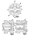
- the wheel shown in fig. 1 has on the shown side a hub cap in the form of a circular disc 1 which is continuous with spokes 2-5, which are in turn continuous with a rim 6.
- the shown wheel is thus intended to allow mounting around the rim of a separate tyre with an internal bead which can be received by a groove 7 in the rim 6.
- the rim has a conical ring-shaped region 8 which together with the hub cap contribute to the authentic shape.
- the wheel is designed to receive an axle end of the type appearing from figs.
- axle 9 has a slot 10 as well as radially projecting beads 11, 12, which can be squeezed against each other because of the presence of the slot 10 when the axle 9 is to be inserted into the wheel and which can snap back in a region 13 co-axial with the wheel and of greater diameter than the diameter of the axle 9.
- the distance measured diametrically across the beads 11, 12 is greater than the bearing face of the wheel hub, which will be explained below.
- the hub of the wheel consists of four ribs 14-17 disposed somewhat behind the hub cap so that the cavity 13 is defined between the hub cap and the ribs.
- the ribs extend radially between the conical area 8 and a bearing face for the axle 9, said bearing face being axially aligned with the outer, circular edge of the disc 1.
- the arc length of the ribs is equal to the arc length between the spokes 2-5. It will thus be appreciated that the beads 11, 12 are visible in fig. 1 where the slot 10 in the axle 9 is shown by broken lines.
- the advantageous features of the wheel of the invention will be understood best in connection with the embodiment of a tool 18A, 18B, 19, 20, for injection moulding of the wheel, as shown in figs. 4 and 5.
- the tool comprises a mould die 18A, which is cut through, and a pair of other mould dies which are symmetrical around the cutting plane of the mould die 18A, and of which the mould die 18B is visible.
- the tool moreover comprises two insertion cores 19, 20, of which at least the core 20 is axially movable.
- the mould dies are also mutually movable longitudinally of the cores.
- the tool is shown in a moulding position, while it is shown in fig. 4 in a position in which it is most visible.
- the tool will be explained below, some parts being provided with three-digit reference numerals where the last two digits can be compared with figs. 1-3, the corresponding wheel parts being indicated at the three-digit tool part.
- the slots 102-105 are continuous with the diametrically opposite slots to provide the spokes 2-5, the slots being interconnected through a circular base whose diameter is equal to the internal distance between the projections 113.
- the end of the core 20 is spaced from the said base at a distance equal to the thickness of the hub cap disc 1. It will thus be appreciated that the moulding material can flow through the cavities 102-105 and collect to provide the disc 1. As appears from fig.
- the core 20 has four ribs, the ribs 21, 22 being visible, which fit snugly in the spaces between the projections 113 as appears from fig. 5.
- the projections 113 and the ends of the ribs on the core 20 thus define the annular cavity 13, while the ribs on the core define the spaces between the ribs 14-17.
- the ribs 27, 22 on the core 20 have a uniform cross-section, but it will be appreciated that the arc distance between the portion of the ribs disposed outside the projection 113 in the moulding position, might be smaller than shown, without this causing problems when the tool is to be removed from the casting.
- the hub cap i.e. 1 and the spokes 2-5 would cause axial overlapping of just a fraction of the cavity defined between the ribs 14-17 (this overlap is only considered within a region co-axial with the hub cap and of greater diameter than the bearing face diameter but of smaller diameter than another predetermined one, such as the smallest diameter of the conical region 8).
- the core 20 could not be withdrawn from the casting, it being borne in mind that the outermost end of the ribs 21, 22 disposed between the projections 113 is to fill the spaces between the last-mentioned projections completely in order to obtain the annular cavity 13 to receive the beads 11, 12 of the axle. It will likewise be appreciated that the diameter of the hub cap disc 1 cannot be greater than the core diameter of the core 20 as, otherwise, the casting cannot release the core 19.
- the structure of the wheel as defined in the characterizing portion of claim 1 is thus the necessary and sufficient condition of the provision of a functional tool which is the prerequisite for mass-production of the wheel.
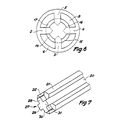
- the hup cap in fig. 6 may have a cruciform recess which is shown in broken lines and corresponds in cross-section to a cruciform shaft whose greatest diameter corresponds to the diameter of the axle end 9 from figs. 2 and 3.
- the recess in the hub cap is rotated through about 45° with respect to the spokes 2-5, the splines of the cruciform shaft will be supported in the hub by the ribs 14-17, and there is thus no risk of shaft splines being received in the space between the ribs 14-17.
- the recess in the hub cap is only open in a direction toward the hub to ensure coherence in the material.
- Fig. 7 shows one end of the insertion core 20 which faces in a direction toward the insertion core 19 in fig. 4.
- a cruciform projection 27 is provided in axial elongation of the previous embodiment, comprising four splines 28-31 which, with respect to the ends of the splines 21, 22 extend forwardly a distance which is smaller than the thickness of the hub cap.
- the projection 27 is received by the core 19 from fig. 4 in the cavity which is defined between the jaws 108, but does not extend right to the bottom of the cavity, in order that the material may merge. It will be appreciated that a longer projection 27 can be matched by an additional depression in the core 19 so that the hub cap will be thicker, enabling provision of a deeper recess to receive the cruciform shaft.
Priority Applications (1)
| Application Number | Priority Date | Filing Date | Title |
|---|---|---|---|
| AT84106095T ATE36462T1 (de) | 1983-06-09 | 1984-05-29 | Rad, insbesondere fuer ein baukastenspiel. |
Applications Claiming Priority (2)
| Application Number | Priority Date | Filing Date | Title |
|---|---|---|---|
| DK2633/83 | 1983-06-09 | ||
| DK263383A DK148834C (da) | 1983-06-09 | 1983-06-09 | Hjul, isaer til et legetoejsbyggesaet |
Publications (3)
| Publication Number | Publication Date |
|---|---|
| EP0128449A2 EP0128449A2 (en) | 1984-12-19 |
| EP0128449A3 EP0128449A3 (en) | 1985-09-18 |
| EP0128449B1 true EP0128449B1 (en) | 1988-08-17 |
Family
ID=8113989
Family Applications (1)
| Application Number | Title | Priority Date | Filing Date |
|---|---|---|---|
| EP84106095A Expired EP0128449B1 (en) | 1983-06-09 | 1984-05-29 | A wheel, in particular for a toy building set |
Country Status (8)
| Country | Link |
|---|---|
| US (1) | US4589702A (da) |
| EP (1) | EP0128449B1 (da) |
| JP (1) | JPH0649110B2 (da) |
| KR (1) | KR930001123B1 (da) |
| AT (1) | ATE36462T1 (da) |
| DE (1) | DE3473412D1 (da) |
| DK (1) | DK148834C (da) |
| ES (1) | ES279747Y (da) |
Families Citing this family (23)
| Publication number | Priority date | Publication date | Assignee | Title |
|---|---|---|---|---|
| US4690656A (en) * | 1985-06-27 | 1987-09-01 | Kenner Parker Toys, Inc. | Wheel and winch assemblies utilizing identical hubs and axles in a toy construction set |
| JPS63233564A (ja) * | 1987-03-23 | 1988-09-29 | Canon Inc | 接合型トランジスタの製造法 |
| DE3830214A1 (de) * | 1988-09-06 | 1990-03-15 | Lautenschlaeger Kg Karl | Laufrolle fuer rollen-ausziehfuehrungen |
| US4963115A (en) * | 1989-12-18 | 1990-10-16 | Smart Design, Inc. | Multipurpose container toy with mountable wheels |
| US5208935A (en) * | 1991-07-16 | 1993-05-11 | Bissell Inc. | Carpet sweeper |
| US5704623A (en) * | 1995-08-01 | 1998-01-06 | Chapman/Leonard Studio Equipment | Mobile camera crane base |
| US6129605A (en) * | 1997-09-24 | 2000-10-10 | Parvia Corporation | Modular base units for a toy building set |
| US5947787A (en) * | 1997-09-24 | 1999-09-07 | Parvia Corporation | Modular lattice substructure for a toy building set |
| US5951356A (en) * | 1997-10-27 | 1999-09-14 | Parvia Corporation | Modular lattice substructure for a toy building set having columns and foundations |
| US5924905A (en) * | 1997-09-24 | 1999-07-20 | Parvia Corporation | Modular terrain for a toy building set |
| US5993283A (en) * | 1997-09-30 | 1999-11-30 | Parvia Corporation | Modular buildings for a toy building set |
| US5865661A (en) * | 1997-10-03 | 1999-02-02 | Parvia Corporation | Toy vehicular drive apparatus |
| US6007401A (en) * | 1997-10-03 | 1999-12-28 | Parvia Corporation | Optoelectric remote control apparatus for guiding toy vehicles |
| US6102770A (en) * | 1997-10-03 | 2000-08-15 | Parvia Corporation | Toy vehicular electromechanical guidance apparatus |
| US6012957A (en) * | 1997-10-27 | 2000-01-11 | Parvia Corporation | Single beam optoelectric remote control apparatus for control of toys |
| DK174581B1 (da) * | 1999-11-17 | 2003-06-30 | Lego As | Et legetøjsbyggesæt |
| DE10154557A1 (de) * | 2001-11-07 | 2003-05-15 | Bsh Bosch Siemens Hausgeraete | Rollenhalter für Geschirrspüler |
| US7032916B2 (en) * | 2003-12-22 | 2006-04-25 | Brevets Futek-Msm Ltee | Stabilizer training wheel with integral suspension |
| US9642987B2 (en) * | 2005-08-31 | 2017-05-09 | C.R. Bard, Inc. | Anchoring system for a catheter |
| KR102126306B1 (ko) | 2012-09-28 | 2020-06-25 | 레고 에이/에스 | 완구 바퀴 조립체 및 그 제조 방법 |
| NZ618908A (en) * | 2012-12-19 | 2014-05-30 | Anthony Innovations Pty Ltd | Cavity door rollers |
| KR200476342Y1 (ko) * | 2014-08-11 | 2015-02-16 | 공대식 | 맛사지 기능을 갖는 자전거 안장 |
| DE202017100168U1 (de) * | 2017-01-13 | 2018-04-16 | Habermaass Gmbh | Gleitlageranordnung für eine Achse eines Kinderspielzeuges sowie Verwendung derselben und ein Kinderspielzeug mit einer Gleitlageranordnung |
Family Cites Families (15)
| Publication number | Priority date | Publication date | Assignee | Title |
|---|---|---|---|---|
| US2741323A (en) * | 1954-05-28 | 1956-04-10 | Massey Harris Ferguson Inc | Rigidifying support for axle mounting extension |
| US2978277A (en) * | 1958-04-01 | 1961-04-04 | Electrolux Ab | Wheel assembly |
| US3107947A (en) * | 1961-11-15 | 1963-10-22 | Flambeau Plastics Corp | Nylon wheel and axle assembly |
| US3360314A (en) * | 1966-02-15 | 1967-12-26 | Loreto Edward G Di | Bearing construction |
| US3454305A (en) * | 1967-02-27 | 1969-07-08 | James Gilmour Jr | Axle mount |
| DE1603541A1 (de) * | 1967-08-04 | 1971-07-08 | Wilhelm Poweleit | Laufradachse fuer Fahrspielzeuge |
| DK123277B (da) * | 1969-02-03 | 1972-06-05 | Lego Syst Billund As | Koblingsanordning mellem et hjul på en aksel. |
| US3566536A (en) * | 1969-07-09 | 1971-03-02 | Mattel Inc | Toy vehicle wheels |
| US3608236A (en) * | 1969-09-03 | 1971-09-28 | Mattel Inc | Steerable toy vehicle |
| US3638356A (en) * | 1970-08-25 | 1972-02-01 | Mattel Inc | Wheel for a toy car |
| DE2152212A1 (de) * | 1971-10-20 | 1973-05-03 | Schuco Spielwaren Schreyer | Rad fuer fahrspielzeuge |
| US4114952A (en) * | 1976-11-05 | 1978-09-19 | Mattel, Inc. | Wheel assembly for a skateboard or the like |
| DE2805138A1 (de) * | 1978-02-07 | 1979-08-09 | Bettag Big Spielwaren | Aus kunststoff gespritztes und zerlegbares spielzeugauto |
| US4193639A (en) * | 1978-04-21 | 1980-03-18 | Tonka Corporation | Mountable wheel for toy vehicle |
| JPS57154493U (da) * | 1981-03-26 | 1982-09-28 |
-
1983
- 1983-06-09 DK DK263383A patent/DK148834C/da not_active IP Right Cessation
-
1984
- 1984-05-29 DE DE8484106095T patent/DE3473412D1/de not_active Expired
- 1984-05-29 AT AT84106095T patent/ATE36462T1/de not_active IP Right Cessation
- 1984-05-29 EP EP84106095A patent/EP0128449B1/en not_active Expired
- 1984-06-06 ES ES1984279747U patent/ES279747Y/es not_active Expired
- 1984-06-08 KR KR1019840003219A patent/KR930001123B1/ko not_active IP Right Cessation
- 1984-06-08 US US06/618,459 patent/US4589702A/en not_active Expired - Lifetime
- 1984-06-09 JP JP59117483A patent/JPH0649110B2/ja not_active Expired - Lifetime
Also Published As
| Publication number | Publication date |
|---|---|
| US4589702A (en) | 1986-05-20 |
| KR850004907A (ko) | 1985-08-19 |
| DK263383A (da) | 1984-12-10 |
| DK148834C (da) | 1986-03-24 |
| DK148834B (da) | 1985-10-21 |
| ATE36462T1 (de) | 1988-09-15 |
| JPS6035601A (ja) | 1985-02-23 |
| ES279747Y (es) | 1986-04-01 |
| DE3473412D1 (en) | 1988-09-22 |
| DK263383D0 (da) | 1983-06-09 |
| ES279747U (es) | 1985-06-16 |
| EP0128449A2 (en) | 1984-12-19 |
| KR930001123B1 (ko) | 1993-02-18 |
| JPH0649110B2 (ja) | 1994-06-29 |
| EP0128449A3 (en) | 1985-09-18 |
Similar Documents
| Publication | Publication Date | Title |
|---|---|---|
| EP0128449B1 (en) | A wheel, in particular for a toy building set | |
| US4243199A (en) | Mold for molding propellers having tapered hubs | |
| EP0549141B1 (en) | A casting mould for casting of vehicle wheels and method for manufacturing them | |
| JPH05187521A (ja) | 歯車製品 | |
| JPH06178503A (ja) | プレーナーカーボンセグメント式整流子 | |
| KR20030083061A (ko) | 터보팬 및 그 제조용 금형 | |
| JPS62243998A (ja) | ラジアルポンプ用のロ−タ | |
| US5078453A (en) | Simulated cap screw and wheel assembly | |
| EP0010826B1 (en) | Method of manufacturing components adapted to be mounted on a shaft; and components, especially steering wheel hubs, so obtained | |
| KR20010072401A (ko) | 자동차용 휠 | |
| JPH0724549A (ja) | 自動車用ホイールの製造方法および自動車用ホイール | |
| JP5435808B2 (ja) | ハブの製造方法および該ハブを備えるホイール | |
| EP3702636B1 (en) | Rotor assembly for a disc brake system | |
| GB2143769A (en) | Mold for molding wheel cover | |
| JPS5840904B2 (ja) | 回転軸にスリツプリングを結合する方法 | |
| US6374493B1 (en) | Wheel casting and wheel assembly | |
| JPH06249193A (ja) | 渦流ブロワの羽根車及びその製造方法 | |
| JPH03193501A (ja) | 自動車用ホイール | |
| JP3385556B2 (ja) | 送風機用多翼車の射出成形方法および射出成形金型 | |
| JPS6233377Y2 (da) | ||
| JPH09220903A (ja) | 自動車用のツーピースホイールとその製造方法 | |
| US4198008A (en) | Reinforcing sleeve for the ends of reel cores | |
| JP3197443U (ja) | 自転車車輪用表示板 | |
| JPH0529921Y2 (da) | ||
| JPS6328703A (ja) | 3ピ−ス型ホイ−ルのリム構造とその製造法 |
Legal Events
| Date | Code | Title | Description |
|---|---|---|---|
| PUAI | Public reference made under article 153(3) epc to a published international application that has entered the european phase |
Free format text: ORIGINAL CODE: 0009012 |
|
| AK | Designated contracting states |
Designated state(s): AT BE CH DE FR GB IT LI LU NL SE |
|
| PUAL | Search report despatched |
Free format text: ORIGINAL CODE: 0009013 |
|
| AK | Designated contracting states |
Designated state(s): AT BE CH DE FR GB IT LI LU NL SE |
|
| 17P | Request for examination filed |
Effective date: 19851007 |
|
| 17Q | First examination report despatched |
Effective date: 19860918 |
|
| R17C | First examination report despatched (corrected) |
Effective date: 19870512 |
|
| RAP1 | Party data changed (applicant data changed or rights of an application transferred) |
Owner name: LEGO A/S |
|
| ITF | It: translation for a ep patent filed |
Owner name: BARZANO' E ZANARDO MILANO S.P.A. |
|
| GRAA | (expected) grant |
Free format text: ORIGINAL CODE: 0009210 |
|
| RAP1 | Party data changed (applicant data changed or rights of an application transferred) |
Owner name: INTERLEGO AG Owner name: LEGO A/S |
|
| AK | Designated contracting states |
Kind code of ref document: B1 Designated state(s): AT BE CH DE FR GB IT LI LU NL SE |
|
| REF | Corresponds to: |
Ref document number: 36462 Country of ref document: AT Date of ref document: 19880915 Kind code of ref document: T |
|
| REF | Corresponds to: |
Ref document number: 3473412 Country of ref document: DE Date of ref document: 19880922 |
|
| ET | Fr: translation filed | ||
| PLBE | No opposition filed within time limit |
Free format text: ORIGINAL CODE: 0009261 |
|
| STAA | Information on the status of an ep patent application or granted ep patent |
Free format text: STATUS: NO OPPOSITION FILED WITHIN TIME LIMIT |
|
| 26N | No opposition filed | ||
| ITTA | It: last paid annual fee | ||
| EPTA | Lu: last paid annual fee | ||
| EAL | Se: european patent in force in sweden |
Ref document number: 84106095.7 |
|
| PGFP | Annual fee paid to national office [announced via postgrant information from national office to epo] |
Ref country code: CH Payment date: 19980511 Year of fee payment: 15 |
|
| PGFP | Annual fee paid to national office [announced via postgrant information from national office to epo] |
Ref country code: AT Payment date: 19980512 Year of fee payment: 15 |
|
| PGFP | Annual fee paid to national office [announced via postgrant information from national office to epo] |
Ref country code: GB Payment date: 19980513 Year of fee payment: 15 |
|
| PGFP | Annual fee paid to national office [announced via postgrant information from national office to epo] |
Ref country code: SE Payment date: 19980518 Year of fee payment: 15 |
|
| PGFP | Annual fee paid to national office [announced via postgrant information from national office to epo] |
Ref country code: FR Payment date: 19980520 Year of fee payment: 15 |
|
| PGFP | Annual fee paid to national office [announced via postgrant information from national office to epo] |
Ref country code: NL Payment date: 19980531 Year of fee payment: 15 |
|
| PGFP | Annual fee paid to national office [announced via postgrant information from national office to epo] |
Ref country code: BE Payment date: 19980603 Year of fee payment: 15 |
|
| PGFP | Annual fee paid to national office [announced via postgrant information from national office to epo] |
Ref country code: LU Payment date: 19980611 Year of fee payment: 15 |
|
| PGFP | Annual fee paid to national office [announced via postgrant information from national office to epo] |
Ref country code: DE Payment date: 19980616 Year of fee payment: 15 |
|
| PG25 | Lapsed in a contracting state [announced via postgrant information from national office to epo] |
Ref country code: LU Free format text: LAPSE BECAUSE OF NON-PAYMENT OF DUE FEES Effective date: 19990529 Ref country code: GB Free format text: LAPSE BECAUSE OF NON-PAYMENT OF DUE FEES Effective date: 19990529 Ref country code: AT Free format text: LAPSE BECAUSE OF NON-PAYMENT OF DUE FEES Effective date: 19990529 |
|
| PG25 | Lapsed in a contracting state [announced via postgrant information from national office to epo] |
Ref country code: SE Free format text: LAPSE BECAUSE OF NON-PAYMENT OF DUE FEES Effective date: 19990530 |
|
| PG25 | Lapsed in a contracting state [announced via postgrant information from national office to epo] |
Ref country code: LI Free format text: LAPSE BECAUSE OF NON-PAYMENT OF DUE FEES Effective date: 19990531 Ref country code: CH Free format text: LAPSE BECAUSE OF NON-PAYMENT OF DUE FEES Effective date: 19990531 Ref country code: BE Free format text: LAPSE BECAUSE OF NON-PAYMENT OF DUE FEES Effective date: 19990531 |
|
| BERE | Be: lapsed |
Owner name: LEGO A/S Effective date: 19990531 |
|
| PG25 | Lapsed in a contracting state [announced via postgrant information from national office to epo] |
Ref country code: NL Free format text: LAPSE BECAUSE OF NON-PAYMENT OF DUE FEES Effective date: 19991201 |
|
| REG | Reference to a national code |
Ref country code: CH Ref legal event code: PL |
|
| GBPC | Gb: european patent ceased through non-payment of renewal fee |
Effective date: 19990529 |
|
| EUG | Se: european patent has lapsed |
Ref document number: 84106095.7 |
|
| PG25 | Lapsed in a contracting state [announced via postgrant information from national office to epo] |
Ref country code: FR Free format text: LAPSE BECAUSE OF NON-PAYMENT OF DUE FEES Effective date: 20000131 |
|
| NLV4 | Nl: lapsed or anulled due to non-payment of the annual fee |
Effective date: 19991201 |
|
| PG25 | Lapsed in a contracting state [announced via postgrant information from national office to epo] |
Ref country code: DE Free format text: LAPSE BECAUSE OF NON-PAYMENT OF DUE FEES Effective date: 20000301 |
|
| REG | Reference to a national code |
Ref country code: FR Ref legal event code: ST |