EP0128355A2 - Bewegungskontrolle für einen Manipulator - Google Patents
Bewegungskontrolle für einen Manipulator Download PDFInfo
- Publication number
- EP0128355A2 EP0128355A2 EP84105194A EP84105194A EP0128355A2 EP 0128355 A2 EP0128355 A2 EP 0128355A2 EP 84105194 A EP84105194 A EP 84105194A EP 84105194 A EP84105194 A EP 84105194A EP 0128355 A2 EP0128355 A2 EP 0128355A2
- Authority
- EP
- European Patent Office
- Prior art keywords
- links
- link
- manipulator
- computing
- signals
- Prior art date
- Legal status (The legal status is an assumption and is not a legal conclusion. Google has not performed a legal analysis and makes no representation as to the accuracy of the status listed.)
- Granted
Links
Images

Classifications
-
- B—PERFORMING OPERATIONS; TRANSPORTING
- B25—HAND TOOLS; PORTABLE POWER-DRIVEN TOOLS; MANIPULATORS
- B25J—MANIPULATORS; CHAMBERS PROVIDED WITH MANIPULATION DEVICES
- B25J9/00—Programme-controlled manipulators
- B25J9/16—Programme controls
- B25J9/1628—Programme controls characterised by the control loop
- B25J9/1648—Programme controls characterised by the control loop non-linear control combined or not with linear control
-
- G—PHYSICS
- G05—CONTROLLING; REGULATING
- G05B—CONTROL OR REGULATING SYSTEMS IN GENERAL; FUNCTIONAL ELEMENTS OF SUCH SYSTEMS; MONITORING OR TESTING ARRANGEMENTS FOR SUCH SYSTEMS OR ELEMENTS
- G05B19/00—Programme-control systems
- G05B19/02—Programme-control systems electric
- G05B19/18—Numerical control [NC], i.e. automatically operating machines, in particular machine tools, e.g. in a manufacturing environment, so as to execute positioning, movement or co-ordinated operations by means of programme data in numerical form
- G05B19/19—Numerical control [NC], i.e. automatically operating machines, in particular machine tools, e.g. in a manufacturing environment, so as to execute positioning, movement or co-ordinated operations by means of programme data in numerical form characterised by positioning or contouring control systems, e.g. to control position from one programmed point to another or to control movement along a programmed continuous path
-
- G—PHYSICS
- G05—CONTROLLING; REGULATING
- G05B—CONTROL OR REGULATING SYSTEMS IN GENERAL; FUNCTIONAL ELEMENTS OF SUCH SYSTEMS; MONITORING OR TESTING ARRANGEMENTS FOR SUCH SYSTEMS OR ELEMENTS
- G05B2219/00—Program-control systems
- G05B2219/30—Nc systems
- G05B2219/33—Director till display
- G05B2219/33076—Optimize time by parallel execution of independent blocks by two processors
-
- G—PHYSICS
- G05—CONTROLLING; REGULATING
- G05B—CONTROL OR REGULATING SYSTEMS IN GENERAL; FUNCTIONAL ELEMENTS OF SUCH SYSTEMS; MONITORING OR TESTING ARRANGEMENTS FOR SUCH SYSTEMS OR ELEMENTS
- G05B2219/00—Program-control systems
- G05B2219/30—Nc systems
- G05B2219/33—Director till display
- G05B2219/33253—Correction data transmission errors, protection against noise, twisted pair
-
- G—PHYSICS
- G05—CONTROLLING; REGULATING
- G05B—CONTROL OR REGULATING SYSTEMS IN GENERAL; FUNCTIONAL ELEMENTS OF SUCH SYSTEMS; MONITORING OR TESTING ARRANGEMENTS FOR SUCH SYSTEMS OR ELEMENTS
- G05B2219/00—Program-control systems
- G05B2219/30—Nc systems
- G05B2219/39—Robotics, robotics to robotics hand
- G05B2219/39178—Compensation inertia arms
-
- G—PHYSICS
- G05—CONTROLLING; REGULATING
- G05B—CONTROL OR REGULATING SYSTEMS IN GENERAL; FUNCTIONAL ELEMENTS OF SUCH SYSTEMS; MONITORING OR TESTING ARRANGEMENTS FOR SUCH SYSTEMS OR ELEMENTS
- G05B2219/00—Program-control systems
- G05B2219/30—Nc systems
- G05B2219/41—Servomotor, servo controller till figures
- G05B2219/41133—Compensation non linear transfer function
Definitions
- the invention is related to programmed manipulators or in a more limited embodiment referred to as industrial "robots"; and more specifically to dynamic controls for manipulators having a fast nonlinear dynamics control loop.
- Equation 1 For a typical 6 link manipulator, the functions J, f and g in Equation 1 are very complex, nonlinear expressions. Because of this complexity, most proposed control schemes are based on breaking down or decoupling Equation 1 into n linear differential equations.
- the decoupling feedback is given by:
- Equation 2 transforms the original system given by equation 1 into the following linear, decoupled system.
- Equation 3 The system described by Equation 3 is easily controlled by any standard control technique.
- Equation 2 constantly changes when the manipulator moves, because J, f and g are dependent on the joint angles.
- the decoupling torques T must be continuously recomputed in real time.
- the required frequency of computation is about 100 times per second. This is the bottleneck in any control scheme, because it involves an excessive number of floating point additions and multiplications.
- Equation 2 Numerous schemes for computation of Equation 2 have been proposed during the last fifteen years. A comprehensive comparison of these techniques is presented by J.M. Hollerbach in his article "A Recursive Lagangian Formulation of Manipulator Dynamics and a Comparative Study of Dynamics Formulation Complexity" IEEE Transactions on Systems, Man and Cybernetics, Vol. 10, No. 11, November 1980, pp 730-736. The most elegant formulation of the problem, based on Lagrange's equation, is due to J.J. Uicker "On the Dynamic Analysis of Spatial Linkages Using 4 x 4 Matrices" Ph. D. Dissertation, Northwestern University, August 1965, and M.E.
- Hollerbach concluded that only very minor improvements can be made to the recursive Newton-Euler formulation disclosed by Luh et al. However, Hollerbach's conclusion only applies to formulations which are very general and can handle manipulators with any number of links and any configuration.
- the dynamic manipulator control described herein is based on the fact that most industrial manipulators are relatively simple geometrically and have from 4 to 7 links. Its computational time, in high level languages, is about five or ten times less than that using the technique taught by Luh et al depending on the implementation.
- the proposed control divides the manipulator into two parts. The first three links (counting from the base) are modeled using classical (non-matrix) Lagrange's equations, with velocities computed in link coordinates. The remaining links (i.e., the wrist) are modeled using recursive Newton-Euler equations.
- the invention is a control system for a multiple link mechanical manipulator or robot having a nonlinear dynamic control loop computing correction factors added to signals generated by the primary linear dynamic control loop correcting the actuator signals for the nonlinear dynamics of the manipulator.
- the primary control comprises a central processing unit having adequate storage and computation capabilities for generating signals indicative of the desired motion of the individual links, a linear dynamic control loop for generating actuator signals controlling the actuators moving the individual manipulator links, and sensors responsive to the position and motion of the individual manipulator links for generating feedback signals to the central processing unit and the linear dynamic control loop.
- the improvement comprising a nonlinear dynamic control loop for correcting the linear control signals for the nonlinear dynamics of the manipulators, said nonlinear dynamics control loop characterized by a nonlinear dynamics control computer for generating correction factors for each of the actuators moving the manipulator links in response to the motion signals generated by the central processing unit and the feedback signals using Lagrangian dynamics for the first three links and recursive Newton-Euler dynamics for the remaining links, and means for summing the correction factors with the associated actuators signals to correct the actuator signals for the nonlinear dynamics of the manipulator.
- manipulator control system is more effective and efficient than the linear control systems of the prior art and the computations for the nonlinear dynamics are capable of being performed at a rate from 5 to 10 times faster than prior art nonlinear control schemes.
- the dynamic manipulator control is based on division of the manipulator into two parts.
- the first part consists of the first three links (counting from the base), and the second part consists of all the remaining links.
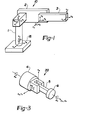
- FIGURE 1 there is shown schematically the first three links of a typical robot arm 10 comparable to the robot arm disclosed by Hohn in U.S. Patent No. 3,909,600.
- the coordinate systems of the links are assigned using the standard convention as taught by Hollerbach cited above, except for link 3, which always has the origin of its coordinates at its end and the (z) axis along its longitudinal axis.
- the first three links, Links 1, 2 and 3 are supported from a base 18 as shown.
- the first link, Link 1 is mounted for rotation from the Base 18 about a vertical axis (z )
- the second link, Link 2 is mounted at the end of Link 1 and is rotatable about a first horizontal axis (z l )
- the third link, Link 3 is mounted at the end of Link 2 and is rotatable about a second horizontal axis (z 2 ).
- the z axis (z 3 ) of Link 3 is along its longitudinal axis as shown.
- the x and y axes complete the right hand system, with x in the vertical plane.
- This proposed model provides a standard interface between the two parts of robots' arm 10, by means of the forces and moments acting on the end of Link 3 to which the wrist is attached.
- any first-three-link arm and any type of wrist will always match.
- the standard convention previously described does not allow such modularity, because coordinates of Link 3 are determined by the type and orientation of the joint at the end of Link 3.
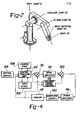
- the joints between the links are identified on FIGURE 2. Conventionally there is the Waist Joint 11, the Shoulder Joint 12, the Elbow Joint 13, the Wrist Joint 14 etc.
- Wrist 20 A typical three degree of freedom Wrist 20 is shown in FIGURE 3. Its reference frame is the system of coordinates of Link 3. As shown, Wrist 20 has a fourth link, Link 4 mounted to the end of Link 3 and is rotatable about the axis (z 3 ) of the Link 3, a fifth link, Link 5 attached to the end of Link 4 and is rotatable about axis (Z 4 ) of Link 4 and Link 6 is rotatable about axis (Z 5 ) of Link 5.
- Link 4 mounted to the end of Link 3 and is rotatable about the axis (z 3 ) of the Link 3
- a fifth link Link 5 attached to the end of Link 4 and is rotatable about axis (Z 4 ) of Link 4
- Link 6 is rotatable about axis (Z 5 ) of Link 5.
- the actuator torques (forces) of the Wrist 20 required by the actuators moving the various links are computed using recursive Newton-Euler equations as taught by Luh et al cited above.
- the computations are referred to the base coordinates through Link 3 coordinates, the velocities and accelerations of which are simple functions of the parameters and variables of the first three links.
- the computation starts with the Link 4, and propagates the velocities and the accelerations out to the last link, and then evaluates the actuator torques (forces) starting from the last link back to actuator moving Link 4. Because of the simplicity of most manipulator wrists, the equations can be written out explicitly for each link.
- Such a formulation uses less than 40% of the arithmetic operations required by the general recursive Newton-Euler algorithm. Further reductions in the computational time for the nonlinear dynamics are due to program execution optimization. Because the first-three-link models and the wrist models are very simple, these models appear in symbolic form in the program. This allows for the grouping of similar terms and other operation saving manipulation well known to those skilled in the art.
- the nonlinear dynamics control also computes the forces and moments required at the end of Link 3, in order to support the Wrist 20. These latter forces and moments are always computed in the standard coordinates of Link 3.
- the second part of the nonlinear dynamics control computes the torques (forces) of actuators for Links 1, 2, and 3, using Lagrangian dynamics. These torques (forces) are primarily due to four effects:
- Tg The contribution due to gravity, Tg, and the contribution due to the wrist, T w , can be written down by inspection.
- Lagrange's equation requires less than 40% of the arithmetic operations required by method taught by Luh et al cited above. Again further savings of computational time can be realized by program execution optimization.
- the equations for the first three links, Links 1, 2 and 3, appear in symbolic form in the program and are conveniently separated into terms corresponding to inertia forces, centripetal forces, Coriolis forces and gravity forces.
- the Wrist 20 is represented in the computations for the first three links by the forces and moments it applies to the Link 3, in numerical form.
- the use of Lagrangian dynamics for the first three links is advantageous for controlling of manipulators which are not open kinematic chains. The developed control easily accommodates for various types of manipulator configurations, because the first-three-link model is derived directly from basic principles of dynamics and are typical to most robot arms.
- FIG. 4 is a detailed block diagram for a manipulator control system.
- the kinematic portion of the system comprises a Central Processing Unit (CPU) 102, a Control Console 104, a Program Store 106 and a Data Store 108.
- the Control Console 104 provides the operator with the necessary controls and displays to generally operate a Manipulator 100 as is known in the art.
- the system will also include other conventional peripheral devices (not shown) such as a machine input / output device concerned with machine oriented functions such as switches, solenoids and other similar devices associated with the Manipuator 100 and a process input / output device for integrating or coordinating the operating of the Manipulator with other machines.
- the operational program of the Central Processing Unit 102 is stored in the Program Store 106 while the data used by the Central Processing Unit 102 in the execution of its program is stored in Data Store 108.
- the data stored in Data Store 108 will include constants used in the calculations, feedback data received from Sensors 110 detecting the actual position, velocity, and or, acceleration of the various links of the Manipulator 100 as well as any partial solutions generated in the execution of the program as may be required.
- the Central Processing Unit 102 in response to the inputs received from the Control Console 104 will execute the program stored in the Program Store 106 using the data stored in Data Store 108, and generate electrical signals indicative of the desired motion of the individual links in the Manipulator 100.
- a conventional dynamic control loop comprising Sum Amplifier Means 112, Servo Amplifiers 114 and Power Amplifiers 116.
- Sum Amplifier 112 subtracts the feedback signals indicative of the actual position, velocity and acceleration of each link from the associated motion signal to produce a difference signal for each manipulator link.
- the Servo Amplifiers 114 convert the individual difference signals to dynamic actuator signals indicative of the torques or forces required to move the associated links of the manipulator along the desired path.
- the individual servo amplifiers execute the linear control laws for manipulator motion and include dynamic compensators for achieving fast and stable response.
- Power Amplifiers 116 amplify the actuator signals to power levels required by the individual actuators to produce the desired torque or force.
- the outputs from Power Amplifiers 116 are received by the individual actuators which move the individual links of the Manipulator 100 with the desired motion.
- the output of Power Amplifiers 116 will be electric signal actuating the electric motors.
- the output of the Power Amplifiers 116 will be hydraulic or pneumatic signals as is known in the art.
- control system as described above represents the current state of the art of manipulator control systems.
- the control law used in these systems is based on ignoring the complex (nonlinear) dynamics of the various moving elements.
- this approach is satisfactory since the complex dynamics of the various elements may be adequately compensated for by programing the control law for a worst case situation and using brute force to impart to each link the desired motion.
- This approach is not the most effective or efficient way to control a manipulator and results in less than optimal response.
- the dynamic response of the Manipulator 100 can be improved by providing a second dynamic control loop which corrects the torque signals output from the Servo Amplifiers 114 for the complex (nonlinear) dynamics of the various moving elements.
- this second dynamic control loop comprises a Nonlinear Dynamics Control Computer 118 for computing a correction factor for each link in the manipulator and a Sum Amplifier Means 120 for suming the computed correction factors with the corresponding torque signals output from the Servo Amplifiers 114.
- the correction factors correcting each of the actuator signals for the complex dynamics of the individual links previously ignored.
- the Nonlinear Dynamics Control Computer 118 receives the desired motion signals generated by the Central Processing Unit 102 and the feedback signals generated by Sensors 110.
- the Nonlinear Dynamics Control Computer 118 then computes the correction factors for the first three links using Lagrange's equations as taught by Hollerbach and the correction factors for the remaining links using the recursive Newton-Euler algorithm described by Luh et al as previously described.
- the computed correction factor for each link is then summed with the associated torque signals in Sum Amplifier Means 120.
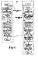
- Sum Amplifier Means 120 comprises a plurality of sum amplifiers, one associated with each of the servo amplifiers of Servo Amplifiers 114 as shall be discussed relative to Figure 5.
- the Nonlinear Dynamics Control Computer 118 may be any commercially available microprocessor, such as the 16 bit Intel 8086 or Motorola 68000 microprocessor or any of the newer 32 bit microprocessors recently introduced or currently under development.
- the Nonlinear Dynamics Control Computer 118 receives directly the desired motion signals from the Central Processing Unit 102 and the feedback signals from Sensors 110 individually identified as Sensors 110-1 through 110-6 associated with the individual Links 1 through 6.
- Each link may have one or more sensors, generating signals indicative of the links current position, velocity, and/or acceleration as is known in the art.
- the Nonlinear Dynamic Control Computer 118 computes the correction factors for the actuator signals output from the individual Servo Amplifiers 114-1 through 114-6 in response to the desired motion signals and the feedback signals.
- the correction factor signals output from the Dynamic Control Computer 118 are individually summed with the associated actuator signals generated by Servo Amplifiers 114-1 through 114-6 in individual Sum Amplifiers 120-1 through 120-6 as shown.
- the corrected actuator signals output from Sum Amplifiers 120-1 through 120-6 are individually amplified in Power Amplifiers 116-1 through 116-6 to drive the individual Actuators 117-1 through 117-6 associated with Links 1 through 6 respectively.
- the individual Sensors 110-1 through 110-6 detect the current state of their respective links and generate feedback signals communicated back to Central Processing Unit 102, Sum Amplifiers 112 and the Nonlinear Dynamics Control Computer 118.
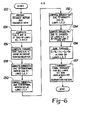
- Nonlinear Dynamics Control Computer 118 The program flow diagram for Nonlinear Dynamics Control Computer 118 is illustrated in Figure 6.
- the program begins by recording the desired motion signals received from the Central Processing Unit 102 and the feedback signals received from the Sensors 110-1 through 110-6 as indicated by block 122.
- the program then proceeds to compute the linear velocity V, linear acceleration V , angular velocity w and angular acceleration w at the end of Link 3 in Link 3 coordinates as indicated by block 124.
- the x axis linear velocity V 3x and angular velocity w 3x are computed using the equations: and where ⁇ 1 , 9 2 and 9 3 are the measured angular velocities of Links 1, 2, and 3 a 2 is the length of Link 2.
- the angles 9 2 and 6 3 are as indicated on Figure 1.
- the linear acceleration V and angular acceleration w are computed as disclosed by Luh et al in the paper "On Line Computational Scheme for Mechanical Manipulators" previously cited. These computational procedures are detailed in Section III entitled “Kinematics of the Links", where V i+1 and w i+1 are the linear and angular displacements at the end of Link 3.
- the next step is to compute the torques and/or forces required from actuators 4, 5 ... n associated with Links 4 through n of the Wrist 20 and the forces and torques required to support the Wrist 20 at the interface between Links 3 and 4 using the recursive Newton-Euler equation as indicated by block 126.
- the details of the procedure are the same as presented by Hollerbach in the article "A Recursive Lagrangian Formulation of Manipulator Dynamics and a Comparative Study of Dynamics Formulation Complexity". The details of the algorithm, are contained in the section entitled; "Recursive Newton-Euler Dynamics”.
- the program then proceeds to compute the torques and forces due to inertia on Links 1, 2 and 3 as indicated by block 128. These computations are conducted through the use of Equation 5.
- Equation 9 The program next proceeds to compute the forces due to gravity as indicated by block 132. Equations for the forces due to gravity are well known and are easily derived for the specific manipulator. These forces are computed using Equation 9.
- the last operation of the Nonlinear Dynamics Control Computer 118 is to output the computed torques and forces as correction factor signals to Sum Amplifiers 120-1 through 120-6, as indicated by Block 137, where they are summed with the actuator signals.
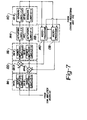
- Microprocessor 138 computes the correction factors for the nonlinear dynamics for the wrist actuators using the recursive Newton-Euler Equation computations of blocks 124 and 126 while Microprocessor 140 computes the correction factors for the nonlinear dynamics of the arm actuators (actuators for Links 1, 2 and 3) using the Lagrange Equation computations of blocks 128 through 132.
- the computations of blocks 134 and 136 are then completed in Microprocessor 140 using the results of the computations of block 126 in Microprocessor 138 in combination with the results of the computations performed in blocks 128, 130, and 132.
- the correction factors computed by Microprocessor 138 for the wrist are added to the outputs from the Servo Amplifiers 114-4, 114-5, ... 114-n collectively designated Servo Amplifiers 114-B by a plurality of individual sum amplifiers, such as Sum Amplifiers 120-4, 120-5 ... 120-n, collectively designated Sum Amplifier 120-B.
- the outputs of the individual Sum Amplifiers 120-B are individually amplified by a like plurality of power amplifiers, Power Amplifiers 116-B which activate the actuators, Actuators 142 associated with Links 4, 5, ... n.
- the sensors associated with Links 4, 5, ... n, Sensors 110-B generate position and velocity feedback signals for the Central Processing Unit 102 and the Dynamic Control Computer 118.
- the correction factors generated by Microprocessor 140, for the first three links, Link 1, 2 and 3, are added to the outputs from Servo Amplifiers 114-1, 114-2 and 114-3, collectively designated Servo Amplifier 114-A by Sum Amplifiers 120-1, 120-2, and 120-3, collectively designated Sum Amplifier 120-A.
- the summed signals are amplified in indivual Power Amplifiers 116-1, 116-2, and 116-3, designated Power Amplifiers 116-A, which activate the actuators for Links 1, 2, and 3, designated Actuators 144.
- the Sensors 110-1, 110-2, 110-3, designated Sensors 110-A generate position and velocity feedback signals to the Central Processing Unit and Dynamic Control Computer as previously described.
- Microprocessor 138 computes the torques and forces for Links 4, 5 ... n using the recursive Newton-Euler Equation as previously described with reference to blocks 124 and 126.
- the torques computed in block 126 for Links 4, 5 ... n are transmitted to Microprocessor 140 to complete the computations of the torques for Links 1, 2 and 3 as indicated by block 146.
- the torques computed by block 126 are also transmitted to Sum Amplifiers 120-4, 120-5, ... 120-n as the correction factors for the actuator signals output from Servo Amplifiers 114-4, 114-5, ... 114-n.
- Microprocessor 140 computes the torques for Links 1, 2 and 3 to balance translation inertia, rotational inertia and gravity using Lagrange's Equations as indicated by blocks 128, 130 and 132.
- the computed torques and forces for Links 4, 5 ... n received from Microprocessor 138 are then utilized in Microprocessor 140 to compute the torques and/or forces required to balance the forces of Links 4, 5 ... n acting on the end of Link 3 as indicated by block 134.
- all of the forces acting on Links 1, 2, and 3 are summed together to generate the nonlinear torques acting on Links 1, 2, and 3 which are output as the correction factors for the respective links.
- the manipulator control system is capable of compensating for the nonlinear dynamics of the manipulator system in a more precise and efficient manner.
- the nonlinear forces acting on links 4, 5, ... n which normally comprise Wrist 20 can efficiently be computed using the recursive Newton-Euler Equations and the nonlinear torques and forces acting on Links 1, 2 and 3 can be computed using Lagrangian Dynamics.
- This nonlinear dynamic control system reduces the required computer time to compute the desired correction factors for each of the links to within a range from 0.003 to 0.004 seconds which is about 5 times faster than using Newton-Euler dynamics as taught by Luh et al. Further by using two microprocessors in the Nonlinear Dynamic Control Computer, the computer time can be further reduced by a factor of approximately 2 making the dynamic manipulator control system almost 10 times faster than the prior art and well within the desired 0.01 seconds.
Landscapes
- Engineering & Computer Science (AREA)
- Physics & Mathematics (AREA)
- Human Computer Interaction (AREA)
- Manufacturing & Machinery (AREA)
- General Physics & Mathematics (AREA)
- Automation & Control Theory (AREA)
- Nonlinear Science (AREA)
- Robotics (AREA)
- Mechanical Engineering (AREA)
- Manipulator (AREA)
- Control Of Position Or Direction (AREA)
Applications Claiming Priority (2)
| Application Number | Priority Date | Filing Date | Title |
|---|---|---|---|
| US503921 | 1983-06-13 | ||
| US06/503,921 US4547858A (en) | 1983-06-13 | 1983-06-13 | Dynamic control for manipulator |
Publications (3)
| Publication Number | Publication Date |
|---|---|
| EP0128355A2 true EP0128355A2 (de) | 1984-12-19 |
| EP0128355A3 EP0128355A3 (en) | 1985-07-10 |
| EP0128355B1 EP0128355B1 (de) | 1987-08-19 |
Family
ID=24004085
Family Applications (1)
| Application Number | Title | Priority Date | Filing Date |
|---|---|---|---|
| EP84105194A Expired EP0128355B1 (de) | 1983-06-13 | 1984-05-08 | Bewegungskontrolle für einen Manipulator |
Country Status (5)
| Country | Link |
|---|---|
| US (1) | US4547858A (de) |
| EP (1) | EP0128355B1 (de) |
| JP (1) | JPS607504A (de) |
| CA (1) | CA1219323A (de) |
| DE (1) | DE3465437D1 (de) |
Cited By (4)
| Publication number | Priority date | Publication date | Assignee | Title |
|---|---|---|---|---|
| EP0605909A1 (de) * | 1992-12-07 | 1994-07-13 | Koninklijke Philips Electronics N.V. | Steuerungseinrichtung |
| WO1998051453A1 (en) * | 1997-05-15 | 1998-11-19 | Abb Ab | A method for supervision of the movement control of a manipulator |
| FR2897700A1 (fr) * | 2006-02-20 | 2007-08-24 | Jean Marc Loriot | Systeme "compliant" a equilibrage auto-regule et a assistance anti-inertielle. |
| WO2023143810A1 (en) * | 2022-01-28 | 2023-08-03 | Kassow Robots Aps | Calculations in a robot |
Families Citing this family (67)
| Publication number | Priority date | Publication date | Assignee | Title |
|---|---|---|---|---|
| JPS59107884A (ja) * | 1982-12-10 | 1984-06-22 | 株式会社日立製作所 | ロボツトの制御方式 |
| US5201630A (en) * | 1984-09-07 | 1993-04-13 | Sony Corporation | Industrial robot with servo system |
| US4620436A (en) * | 1984-10-09 | 1986-11-04 | Hitachi, Ltd. | Method and apparatus for calibrating transformation matrix of force sensor |
| JPS62187210A (ja) * | 1986-02-14 | 1987-08-15 | Fanuc Ltd | パルス分配型位置検出装置 |
| US4975856A (en) * | 1986-02-18 | 1990-12-04 | Robotics Research Corporation | Motion controller for redundant or nonredundant linkages |
| US4763276A (en) * | 1986-03-21 | 1988-08-09 | Actel Partnership | Methods for refining original robot command signals |
| JPS62232006A (ja) * | 1986-04-02 | 1987-10-12 | Yokogawa Electric Corp | ロボツト・システム |
| JPS62286101A (ja) * | 1986-06-04 | 1987-12-12 | Toshiba Corp | 多自由度マニピユレ−タの制御装置 |
| JPH071463B2 (ja) * | 1986-06-30 | 1995-01-11 | フアナツク株式会社 | ロボツト制御装置 |
| JPS6327904A (ja) * | 1986-07-22 | 1988-02-05 | Hitachi Ltd | サ−ボ機構装置の位置修正制御方式 |
| DE3782795T2 (de) * | 1986-09-29 | 1993-06-09 | Asea Ab | Verfahren und vorrichtung zur optimalen parameterregelung von reglern, die rotierende und/oder lineare bewegungen eines industrieroboters steuern. |
| US4786847A (en) * | 1986-11-20 | 1988-11-22 | Unimation Inc. | Digital control for multiaxis robots |
| EP0268491A3 (de) * | 1986-11-20 | 1988-08-03 | Unimation Inc. | Vielachsenroboter mit Bewegungskontrolle |
| EP0269372A3 (de) * | 1986-11-20 | 1988-08-17 | Unimation Inc. | Roboter mit mikroprozessorgestützter Digitalkontrolle |
| US4763055A (en) * | 1986-11-20 | 1988-08-09 | Westinghouse Electric Corp. | Digital robot control having high performance servo control system |
| EP0269373A3 (de) * | 1986-11-20 | 1988-08-17 | Unimation Inc. | Steuerung eines Mehrachsenroboters mit Schutzsystem mit Überwachung von Leistung und Geschwindigkeit |
| EP0269374A3 (de) * | 1986-11-20 | 1988-08-24 | Unimation Inc. | Modules Kontrollsystem für einen Roboter |
| EP0268490A3 (de) * | 1986-11-20 | 1988-08-24 | Unimation Inc. | Digitale Robotersteuerung mit Kontrolle des Gelenkmotors und rückgekoppelten Strom-Sensorsystemen für die Verdrehkraft |
| US4851748A (en) * | 1986-11-20 | 1989-07-25 | Westinghouse Electric Corp. | Basic digital multi-axis robot control having modular performance expansion capability |
| US4716350A (en) * | 1986-12-08 | 1987-12-29 | Ford Motor Company | Method to avoid singularity in a robot mechanism |
| JPS63190583A (ja) * | 1987-01-29 | 1988-08-08 | Fanuc Ltd | 速度制御方式 |
| JP2645004B2 (ja) * | 1987-02-27 | 1997-08-25 | 株式会社東芝 | 多自由度マニピユレータの制御装置 |
| JP2713899B2 (ja) * | 1987-03-30 | 1998-02-16 | 株式会社日立製作所 | ロボツト装置 |
| US4860215A (en) * | 1987-04-06 | 1989-08-22 | California Institute Of Technology | Method and apparatus for adaptive force and position control of manipulators |
| US5023808A (en) * | 1987-04-06 | 1991-06-11 | California Institute Of Technology | Dual-arm manipulators with adaptive control |
| JPS63314606A (ja) * | 1987-06-18 | 1988-12-22 | Fanuc Ltd | 多関節ロボットの制御装置 |
| US4845627A (en) * | 1987-10-01 | 1989-07-04 | Eaton Corporation | Remote programmable controller |
| US4864205A (en) * | 1987-10-09 | 1989-09-05 | Hewlett-Packard Company | Method for coordinated control of motion devices |
| JPH01116704A (ja) * | 1987-10-30 | 1989-05-09 | Fanuc Ltd | 産業ロボットの動作制御方式 |
| US4908777A (en) * | 1988-01-27 | 1990-03-13 | Storage Technology Corporation | Robot arm calibration system |
| US5129044A (en) * | 1988-03-01 | 1992-07-07 | Hitachi Construction Machinery Co., Ltd. | Position/force controlling apparatus for working machine with multiple of degrees of freedom |
| US4925312A (en) * | 1988-03-21 | 1990-05-15 | Staubli International Ag | Robot control system having adaptive feedforward torque control for improved accuracy |
| JPH01252389A (ja) * | 1988-03-31 | 1989-10-09 | Agency Of Ind Science & Technol | マニピュレータ及びその制御方法 |
| US4916635A (en) * | 1988-09-12 | 1990-04-10 | Massachusetts Institute Of Technology | Shaping command inputs to minimize unwanted dynamics |
| JPH02198783A (ja) * | 1989-01-23 | 1990-08-07 | Fanuc Ltd | 産業用ロボットの位置決め補正方式 |
| JPH02297602A (ja) * | 1989-05-12 | 1990-12-10 | Fanuc Ltd | 非線形項補償を含むスライディングモード制御方式 |
| US5049796A (en) * | 1989-05-17 | 1991-09-17 | The United States Of America As Represented By The Administrator Of The National Aeronautics And Space Administration | Robust high-performance control for robotic manipulators |
| US5055755A (en) * | 1989-05-31 | 1991-10-08 | Kabushiki Kaisha Toshiba | Distribution control apparatus |
| WO1992008177A1 (en) * | 1990-10-30 | 1992-05-14 | Gmf Robotics Corporation | Hybrid control method and system for controlling the flow of liquid coating material |
| US5430643A (en) * | 1992-03-11 | 1995-07-04 | The United States Of America As Represented By The Administrator Of The National Aeronautics And Space Administration | Configuration control of seven degree of freedom arms |
| US5311109A (en) * | 1992-03-31 | 1994-05-10 | Honda Giken Kogyo Kabushiki Kaisha | Locomotion control system for legged mobile robot |
| US5546508A (en) * | 1992-04-03 | 1996-08-13 | The United States Of America As Represented By The Administrator Of The National Aeronautics And Space Administration | Controlling flexible robot arms using high speed dynamics process |
| US5377310A (en) * | 1992-04-03 | 1994-12-27 | The United States Of America As Represented By The Administrator Of The National Aeronautics And Space Administration | Controlling under-actuated robot arms using a high speed dynamics |
| DE4218782A1 (de) * | 1992-06-06 | 1993-01-14 | Zahnradfabrik Friedrichshafen | Verfahren zum ansteuern von elektrischen, stromgesteuerten stellgliedern |
| US5294873A (en) * | 1992-10-27 | 1994-03-15 | The United States Of America As Represented By The Administrator Of The National Aeronautics And Space Administration | Kinematic functions for redundancy resolution using configuration control |
| US5486995A (en) * | 1994-03-17 | 1996-01-23 | Dow Benelux N.V. | System for real time optimization |
| CA2184832A1 (en) * | 1994-03-17 | 1995-09-21 | Johannes H.A. Krist | System for real time optimization and profit depiction |
| JP3681431B2 (ja) * | 1995-02-21 | 2005-08-10 | ファナック株式会社 | 直交座標系上で柔らかさが調節可能なサーボ系 |
| US6774885B1 (en) * | 1999-01-20 | 2004-08-10 | Motek B.V. | System for dynamic registration, evaluation, and correction of functional human behavior |
| US6876991B1 (en) | 1999-11-08 | 2005-04-05 | Collaborative Decision Platforms, Llc. | System, method and computer program product for a collaborative decision platform |
| US6725101B2 (en) * | 2000-12-13 | 2004-04-20 | Xerox Corporation | Method and apparatus for using fast fourier transform feedback to compensate for non-linear motion |
| US20070158515A1 (en) * | 2006-01-03 | 2007-07-12 | Jay Dittmer | Motorized mount for electronic display |
| US20070158627A1 (en) * | 2006-01-04 | 2007-07-12 | Jay Dittmer | Motorized lift for electronic display device |
| JP5962020B2 (ja) | 2012-01-17 | 2016-08-03 | セイコーエプソン株式会社 | ロボット制御装置、ロボットシステム、ロボット及びロボット制御方法 |
| JP5966372B2 (ja) | 2012-01-17 | 2016-08-10 | セイコーエプソン株式会社 | ロボット制御装置、ロボットシステム、ロボット制御方法及びロボット |
| JP6111563B2 (ja) * | 2012-08-31 | 2017-04-12 | セイコーエプソン株式会社 | ロボット |
| JP6036476B2 (ja) * | 2013-03-28 | 2016-11-30 | セイコーエプソン株式会社 | ロボット |
| DE102015225534A1 (de) * | 2015-12-17 | 2017-02-09 | Carl Zeiss Smt Gmbh | Positionier-Vorrichtung, insbesondere für eine Projektionsbelichtungsanlage, und Positionier-Verfahren mittels einer derartigen Positionier-Vorrichtung |
| US10065313B2 (en) * | 2016-12-07 | 2018-09-04 | Harris Corporation | Robot manipulator system |
| JP2017056558A (ja) * | 2017-01-06 | 2017-03-23 | セイコーエプソン株式会社 | ロボット |
| CN109202904B (zh) * | 2018-09-30 | 2020-10-20 | 湘潭大学 | 一种机械臂运动路径的确定方法及确定系统 |
| WO2022161245A1 (zh) * | 2021-01-29 | 2022-08-04 | 苏州艾利特机器人有限公司 | 一种提高机器人关节转矩检测精度的方法及多关节机器人 |
| CN113283116B (zh) * | 2021-06-16 | 2022-08-05 | 北京理工大学 | 多信息融合的人体运动分析方法和装置 |
| CN116945154A (zh) * | 2023-03-31 | 2023-10-27 | 腾讯科技(深圳)有限公司 | 机械臂的控制方法、装置、设备及存储介质 |
| CN117331311B (zh) * | 2023-09-21 | 2024-05-14 | 中山大学 | 基于免加速度递归滤波回归的机器人动力学参数估计方法 |
| CN117047782B (zh) * | 2023-10-11 | 2023-12-08 | 中建四局安装工程有限公司 | 适用于三关节机械手的控制方法和装置、终端及介质 |
| CN117930833B (zh) * | 2023-12-28 | 2024-12-27 | 遨博(江苏)机器人有限公司 | 机器人轨迹的评估优化方法 |
Family Cites Families (13)
| Publication number | Priority date | Publication date | Assignee | Title |
|---|---|---|---|---|
| JPS5425196B2 (de) * | 1972-03-16 | 1979-08-25 | ||
| US4021651A (en) * | 1972-06-20 | 1977-05-03 | Kawasaki Jukogyo Kabushiki Kaisha | Programmed manipulator |
| US3909600A (en) * | 1972-06-26 | 1975-09-30 | Cincinnati Milacron Inc | Method and apparatus for controlling an automation along a predetermined path |
| US4011437A (en) * | 1975-09-12 | 1977-03-08 | Cincinnati Milacron, Inc. | Method and apparatus for compensating for unprogrammed changes in relative position between a machine and workpiece |
| DE2656433C3 (de) * | 1976-12-14 | 1983-11-17 | Fraunhofer-Gesellschaft Zur Foerderung Der Angewandten Forschung E.V., 8000 Muenchen | Verfahren und Anordnung zur Regelung von Manipulatoen und industriellen Robotern |
| US4068156A (en) * | 1977-03-01 | 1978-01-10 | Martin Marietta Corporation | Rate control system for manipulator arms |
| US4338672A (en) * | 1978-04-20 | 1982-07-06 | Unimation, Inc. | Off-line teach assist apparatus and on-line control apparatus |
| JPS5840761B2 (ja) * | 1978-12-20 | 1983-09-07 | 工業技術院長 | 人間腕形マニピュレ−タの制御装置 |
| US4243923A (en) * | 1979-01-22 | 1981-01-06 | Massachusetts Institute Of Technology | Servo-controlled mobility device |
| JPS5611510A (en) * | 1979-07-10 | 1981-02-04 | Fanuc Ltd | Numerical control system |
| US4283764A (en) * | 1979-10-12 | 1981-08-11 | Nordson Corporation | Manually programmable robot with power-assisted motion during programming |
| DE3038436C2 (de) * | 1980-10-11 | 1985-08-29 | Jungheinrich Unternehmensverwaltung Kg, 2000 Hamburg | Positionierregelkreis für Manipulatoren |
| JPS57156183A (en) * | 1981-03-20 | 1982-09-27 | Hitachi Ltd | Method and device for controlling course of robot |
-
1983
- 1983-06-13 US US06/503,921 patent/US4547858A/en not_active Expired - Fee Related
-
1984
- 1984-05-08 EP EP84105194A patent/EP0128355B1/de not_active Expired
- 1984-05-08 DE DE8484105194T patent/DE3465437D1/de not_active Expired
- 1984-05-28 CA CA000455266A patent/CA1219323A/en not_active Expired
- 1984-06-13 JP JP59120072A patent/JPS607504A/ja active Pending
Cited By (4)
| Publication number | Priority date | Publication date | Assignee | Title |
|---|---|---|---|---|
| EP0605909A1 (de) * | 1992-12-07 | 1994-07-13 | Koninklijke Philips Electronics N.V. | Steuerungseinrichtung |
| WO1998051453A1 (en) * | 1997-05-15 | 1998-11-19 | Abb Ab | A method for supervision of the movement control of a manipulator |
| FR2897700A1 (fr) * | 2006-02-20 | 2007-08-24 | Jean Marc Loriot | Systeme "compliant" a equilibrage auto-regule et a assistance anti-inertielle. |
| WO2023143810A1 (en) * | 2022-01-28 | 2023-08-03 | Kassow Robots Aps | Calculations in a robot |
Also Published As
| Publication number | Publication date |
|---|---|
| EP0128355A3 (en) | 1985-07-10 |
| CA1219323A (en) | 1987-03-17 |
| EP0128355B1 (de) | 1987-08-19 |
| DE3465437D1 (en) | 1987-09-24 |
| JPS607504A (ja) | 1985-01-16 |
| US4547858A (en) | 1985-10-15 |
Similar Documents
| Publication | Publication Date | Title |
|---|---|---|
| EP0128355B1 (de) | Bewegungskontrolle für einen Manipulator | |
| Zheng et al. | Joint torques for control of two coordinated moving robots | |
| Luh et al. | Constrained relations between two coordinated industrial robots for motion control | |
| JP5109573B2 (ja) | 制御システム及び制御方法、並びにロボット装置 | |
| Zheng et al. | Control of two coordinated robots in motion | |
| US8140189B2 (en) | Apparatus and method for computing operational-space physical quantity | |
| US9031699B2 (en) | Kinematic predictor for articulated mechanisms | |
| US5159249A (en) | Method and apparatus for controlling robot motion at and near singularities and for robot mechanical design | |
| Shin et al. | Compliant control of robotic manipulators with resolved acceleration | |
| EP0464649B1 (de) | Robotersteuerung mit Inertialkoordinatensystem | |
| Gorce et al. | Grasping, coordination and optimal force distribution in multifingered mechanisms | |
| EP0383951A1 (de) | Senkrecht gegliederter roboter | |
| JPH04343690A (ja) | 多関節マニピュレータの関節摩擦補償方法 | |
| JPH07256580A (ja) | 複腕協調制御装置 | |
| Mudge et al. | Unifying robot arm control | |
| Stanišié et al. | Inverse velocity and acceleration solutions of serial robot arm subassemblies using the canonical coordinate system | |
| JPH0788786A (ja) | マニピュレータおよびその制御方法 | |
| JP2520006B2 (ja) | ロボット教示方式 | |
| Stanišié | Coordinate systems and the inverse velocity problem of manipulators with spherical wrists | |
| Ramirez-Zamora et al. | Kinematics modeling and experimental validation of a cyberforce haptic device based on passive control system | |
| Lauer et al. | Transputer network controls robot axes | |
| JPS63276607A (ja) | マニピュレータ装置 | |
| Wang et al. | Nonlinear robust hybrid control of robot manipulators | |
| JPH04300173A (ja) | マスタスレーブマニピュレータ | |
| WO2024070568A1 (ja) | 多関節ロボットの制御方法、ロボットシステム、プログラム、及び、物品の製造方法 |
Legal Events
| Date | Code | Title | Description |
|---|---|---|---|
| PUAI | Public reference made under article 153(3) epc to a published international application that has entered the european phase |
Free format text: ORIGINAL CODE: 0009012 |
|
| AK | Designated contracting states |
Designated state(s): DE FR GB IT |
|
| RHK1 | Main classification (correction) |
Ipc: B25J 9/00 |
|
| PUAL | Search report despatched |
Free format text: ORIGINAL CODE: 0009013 |
|
| RHK1 | Main classification (correction) |
Ipc: B25J 9/18 |
|
| AK | Designated contracting states |
Designated state(s): DE FR GB IT |
|
| 17P | Request for examination filed |
Effective date: 19851211 |
|
| 17Q | First examination report despatched |
Effective date: 19861105 |
|
| RAP1 | Party data changed (applicant data changed or rights of an application transferred) |
Owner name: ALLIED CORPORATION |
|
| ITF | It: translation for a ep patent filed | ||
| GRAA | (expected) grant |
Free format text: ORIGINAL CODE: 0009210 |
|
| AK | Designated contracting states |
Kind code of ref document: B1 Designated state(s): DE FR GB IT |
|
| REF | Corresponds to: |
Ref document number: 3465437 Country of ref document: DE Date of ref document: 19870924 |
|
| ET | Fr: translation filed | ||
| PLBE | No opposition filed within time limit |
Free format text: ORIGINAL CODE: 0009261 |
|
| STAA | Information on the status of an ep patent application or granted ep patent |
Free format text: STATUS: NO OPPOSITION FILED WITHIN TIME LIMIT |
|
| 26N | No opposition filed | ||
| PG25 | Lapsed in a contracting state [announced via postgrant information from national office to epo] |
Ref country code: GB Effective date: 19890508 |
|
| GBPC | Gb: european patent ceased through non-payment of renewal fee | ||
| PG25 | Lapsed in a contracting state [announced via postgrant information from national office to epo] |
Ref country code: FR Free format text: LAPSE BECAUSE OF NON-PAYMENT OF DUE FEES Effective date: 19900131 |
|
| PG25 | Lapsed in a contracting state [announced via postgrant information from national office to epo] |
Ref country code: DE Effective date: 19900201 |
|
| REG | Reference to a national code |
Ref country code: FR Ref legal event code: ST |