US8140189B2 - Apparatus and method for computing operational-space physical quantity - Google Patents
Apparatus and method for computing operational-space physical quantity Download PDFInfo
- Publication number
- US8140189B2 US8140189B2 US11/544,052 US54405206A US8140189B2 US 8140189 B2 US8140189 B2 US 8140189B2 US 54405206 A US54405206 A US 54405206A US 8140189 B2 US8140189 B2 US 8140189B2
- Authority
- US
- United States
- Prior art keywords
- operational space
- force
- acceleration
- physical quantity
- computing
- Prior art date
- Legal status (The legal status is an assumption and is not a legal conclusion. Google has not performed a legal analysis and makes no representation as to the accuracy of the status listed.)
- Active, expires
Links
- 238000000034 method Methods 0.000 title claims description 60
- 230000001133 acceleration Effects 0.000 claims abstract description 322
- 239000011159 matrix material Substances 0.000 claims abstract description 239
- 238000004364 calculation method Methods 0.000 claims abstract description 162
- 230000005484 gravity Effects 0.000 claims description 62
- 230000033001 locomotion Effects 0.000 claims description 27
- 230000008859 change Effects 0.000 claims description 7
- 238000004590 computer program Methods 0.000 claims 1
- 238000005259 measurement Methods 0.000 description 23
- 210000001503 joint Anatomy 0.000 description 19
- 238000012545 processing Methods 0.000 description 19
- 238000004088 simulation Methods 0.000 description 17
- 230000010399 physical interaction Effects 0.000 description 16
- 238000006243 chemical reaction Methods 0.000 description 9
- 238000005457 optimization Methods 0.000 description 7
- 210000002414 leg Anatomy 0.000 description 6
- 230000035807 sensation Effects 0.000 description 6
- 230000006870 function Effects 0.000 description 5
- 238000004422 calculation algorithm Methods 0.000 description 4
- 239000003638 chemical reducing agent Substances 0.000 description 4
- 230000014509 gene expression Effects 0.000 description 4
- 210000004197 pelvis Anatomy 0.000 description 4
- 238000011160 research Methods 0.000 description 4
- 239000002699 waste material Substances 0.000 description 4
- 210000000544 articulatio talocruralis Anatomy 0.000 description 3
- 238000013461 design Methods 0.000 description 3
- 210000002310 elbow joint Anatomy 0.000 description 3
- 210000001624 hip Anatomy 0.000 description 3
- 210000004394 hip joint Anatomy 0.000 description 3
- 230000007246 mechanism Effects 0.000 description 3
- 230000009467 reduction Effects 0.000 description 3
- 210000000323 shoulder joint Anatomy 0.000 description 3
- 210000003857 wrist joint Anatomy 0.000 description 3
- 230000008901 benefit Effects 0.000 description 2
- 238000010586 diagram Methods 0.000 description 2
- 230000004069 differentiation Effects 0.000 description 2
- 239000012636 effector Substances 0.000 description 2
- 210000003127 knee Anatomy 0.000 description 2
- 230000004048 modification Effects 0.000 description 2
- 238000012986 modification Methods 0.000 description 2
- 238000006467 substitution reaction Methods 0.000 description 2
- 230000002123 temporal effect Effects 0.000 description 2
- 230000004075 alteration Effects 0.000 description 1
- 238000013459 approach Methods 0.000 description 1
- 238000010276 construction Methods 0.000 description 1
- 238000006073 displacement reaction Methods 0.000 description 1
- 230000000694 effects Effects 0.000 description 1
- 238000009472 formulation Methods 0.000 description 1
- 210000000629 knee joint Anatomy 0.000 description 1
- 238000012067 mathematical method Methods 0.000 description 1
- 239000000203 mixture Substances 0.000 description 1
- 230000008569 process Effects 0.000 description 1
- 238000012827 research and development Methods 0.000 description 1
- 230000007704 transition Effects 0.000 description 1
- 230000002618 waking effect Effects 0.000 description 1
- 210000000707 wrist Anatomy 0.000 description 1
Images


Classifications
-
- B—PERFORMING OPERATIONS; TRANSPORTING
- B25—HAND TOOLS; PORTABLE POWER-DRIVEN TOOLS; MANIPULATORS
- B25J—MANIPULATORS; CHAMBERS PROVIDED WITH MANIPULATION DEVICES
- B25J9/00—Programme-controlled manipulators
- B25J9/16—Programme controls
- B25J9/1656—Programme controls characterised by programming, planning systems for manipulators
- B25J9/1671—Programme controls characterised by programming, planning systems for manipulators characterised by simulation, either to verify existing program or to create and verify new program, CAD/CAM oriented, graphic oriented programming systems
-
- G—PHYSICS
- G05—CONTROLLING; REGULATING
- G05B—CONTROL OR REGULATING SYSTEMS IN GENERAL; FUNCTIONAL ELEMENTS OF SUCH SYSTEMS; MONITORING OR TESTING ARRANGEMENTS FOR SUCH SYSTEMS OR ELEMENTS
- G05B2219/00—Program-control systems
- G05B2219/30—Nc systems
- G05B2219/39—Robotics, robotics to robotics hand
- G05B2219/39184—Forward compensation in robot world space, inverse in joint space
-
- G—PHYSICS
- G05—CONTROLLING; REGULATING
- G05B—CONTROL OR REGULATING SYSTEMS IN GENERAL; FUNCTIONAL ELEMENTS OF SUCH SYSTEMS; MONITORING OR TESTING ARRANGEMENTS FOR SUCH SYSTEMS OR ELEMENTS
- G05B2219/00—Program-control systems
- G05B2219/30—Nc systems
- G05B2219/39—Robotics, robotics to robotics hand
- G05B2219/39299—Learn forward dynamics
Definitions
- the present invention contains subject matter related to Japanese Patent Application JP 2005-298090 filed in the Japanese Patent Office on Oct. 12, 2005, the entire contents of which are incorporated herein by reference.
- the present invention relates to an apparatus and a method for computing an operational-space physical quantity that is required for controlling the operation of a robot (such as a legged robot) that has a complicated link mechanism and that carries out a task while interacting with the external world and, in particular, to an apparatus and a method for computing an operational-space physical quantity that is required for precisely and flexibly controlling the velocity and the acceleration in accordance with an external force by applying a force control to the operation of a link structure composed of a plurality of linked rigid bodies.
- a robot such as a legged robot
- the present invention relates to an apparatus and a method for computing an operational-space physical quantity in an operational space that defines a relationship between a force exerted on a link structure driven by a force control system and acceleration, and still more particularly, to an apparatus and a method for computing an operational-space physical quantity that are applicable even when an operational space relates to the positions and orientations of a plurality of points of a structure.
- the research and development relating to the structure and the stable walking control of legged mobile robots has been successful, and therefore, a practical application of the legged moving robot is expected to become increasingly widespread.
- These legged mobile robots are unstable compared with crawler robots, and therefore, it is difficult to control the posture and the waking of the legged mobile robots.
- the legged mobile robots have an advantage in that flexible walking and moving operations (such as operations of moving stairways and riding over an obstacle) can be achieved.
- a humanoid robot has been proposed that has legs as a moving mechanism and that can generate a stable moving pattern of the transition between an on-the-ground state and an off-the-ground state in real time (refer to, for example, Japanese Unexamined Patent Application Publication No. 2004-167676).
- the position control is basically aimed at keeping the position. Accordingly, the position control is known as a “hard control”.
- the position control is not suitable for flexibly responding an external force and precisely controlling the velocity and acceleration.
- the position control is not suitable for the partner-type legged robot by nature.
- it is desirable that the partner-type legged robot is driven by a force control system, although the control rule and the system configuration are complicated.
- the operational space refers to a space used to describe a relationship between a force acting on a robot and the acceleration generated for the robot.
- the operational space is essential.
- examples of the constraint conditions include a constraint condition for self-interference of the robot, a constraint condition involved in an available joint angle, an event indicating that a hand fits an object, and an event indicating that the right and left eyes are horizontally aligned.
- a vector generated by unifying the values of the joints is called as a generalized variable.
- This generalized variable is represented using a symbol “q”.
- examples of the operational space include the Cartesian coordinate system for carrying out a task, such as the position and orientation of a hand provided on the top end of a manipulator or other end-effectors (refer to, for example, “A unified approach to motion and force control of robot manipulators: The operational space formulation,” IEEE Journal of Robotics and Automation, RA-3(1), pp. 43-53, 1987 (hereinafter referred to as “Non-patent document 1”)).
- the operational space namely, the relationship between the acceleration of a physical quantity x and a force will be described in more detail below.
- the inverse operational space inertia matrix is an important physical quantity that can be applied to many technical fields including force control, force simulation, computer animation, posture editing, and external force estimation.
- a method has been proposed for generating motions of joints of a human-like link structure by computing a joint acceleration while taking into account a constraint condition involved in forward dynamics or by simultaneously solving an equation of a forward dynamics constraint condition formulated using a force exerted on a link and an inverse operational space inertia matrix representing a relationship between the force and the acceleration caused by the force and an equation of a kinetic constraint condition (refer to, for example, Japanese Unexamined Patent Application Publication No. 2003-231077).
- equation (2) In order to compute the inverse operational space inertia matrix using equation (2), a large amount of computation is required. Accordingly, the computation of equation (2) is not suitable for real-time processing.
- the inertia matrix H has a size of N ⁇ N.
- the size of ⁇ ⁇ 1 is M ⁇ M. If N>M and the computation is performed using equation (2), waste of computational time occurs, as can be easily seen.
- the number of joints is more than or equal to 30 (i.e., N ⁇ 30), the difference between N and M is noticeable. Accordingly, it is difficult to compute the inverse operational space inertia matrix in real time. In most cases, the number M of operational degrees of freedom is smaller than the number N of degrees of freedom of a robot. Therefore, it is desirable that the inverse operational space inertia matrix ⁇ ⁇ 1 can be directly computed without using the inertia matrix H.
- Non-Patent document 2 a direct solution of an inverse operational space inertia matrix.
- a method has been proposed in which the block diagonal components and the block non-diagonal components of the inverse operational space inertia matrix ⁇ ⁇ 1 are directly computed by means of dynamics calculation using physical quantities known as an acceleration propagator and a force propagator (refer to, for example, “Operational Space Dynamics: Efficient Algorithms for Modeling and Control of Branching Mechanisms,” Proc. of the 2000 IEEE Int. Conf. on Robotics and Automation, pp. 850-856, 2000 (hereinafter referred to as “Non-Patent document 2”)).
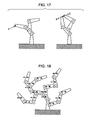
- this method can be only applied to the case where one operational space corresponds to the position and orientation of one point of the link structure. For example, for a multi-axis robot shown in FIG. 17 , if a force corresponding to an operational space is applied to only a point A shown in the left section of FIG. 17 , this method can be applied. However, as shown in the right section of FIG. 17 , if forces corresponding to an operational space are applied to more than or equal to two points (such as the relative position and orientation between points B and C), this method cannot be applied.
- the operational space inertia inverse matrices for the points B and C are computed first. Then, by computing the difference between the two matrices, the inverse operational space inertia matrix for the operational space can be eventually computed. However, waste of computational time occurs. Additionally, when collision between the points B and C of application of force, that is, the interference between the links of a mobile robot (self-interference) is taken into account, the inertia matrix H is essential.
- the center of gravity and the kinetic momentum of the entire structure should be controlled on the basis of the concept of operational space.
- the center of gravity and the kinetic momentum of the whole body are essential factors.
- the operational space is defined by the center of gravity and the kinetic momentum
- a force corresponding to one operational space is applied on the centers of gravity of all of links, as shown in FIG. 18 , which is described in more detail below.
- the method for directly computing the inverse operational space inertia matrix cannot be applied.
- the present invention provides an excellent apparatus and a method for computing an operational-space physical quantity required for accurately controlling the velocity and the acceleration of a robot (such as a legged robot) that has a complicated structure and that carries out a task while interacting with the external world by using a force control.
- a robot such as a legged robot
- the present invention further provides an excellent apparatus and a method for computing an inverse operational space inertia matrix and the associated bias acceleration that are important physical quantities required for operating a complicated link structure (such as a robot) for carrying out a task under the force control at high speed.
- the present invention further provides an excellent apparatus and a method for appropriately achieving a force control of a legged mobile robot by directly and efficiently computing an inverse operational space inertia matrix even when an operational space relates to the positions and orientations of a plurality of points of a structure.
- the present invention further provides an excellent apparatus and a method capable of controlling the kinetic momentum of the entire structure under the force control by defining an operational space (a kinetic momentum operational space) for a physical quantity having no operational points (such as the center of gravity and angular momentum) and computing the inverse operational space inertia matrix of the operational space.
- an operational space a kinetic momentum operational space
- a physical quantity having no operational points such as the center of gravity and angular momentum
- An embodiment of the present invention addresses the problems described above by providing an operational space physical quantity calculation apparatus for computing a physical quantity in an operational space describing a relationship between a force and acceleration acting on a link structure including a plurality of linked rigid bodies.
- the operational space physical quantity calculation apparatus includes forward dynamics calculating means for performing a forward dynamics calculation on the basis of force information about a force acting on the link structure in order to obtain an acceleration occurring at certain points of the link structure and operational space physical quantity computing means for computing an inverse operational space inertia matrix and an operational space bias acceleration by causing the forward dynamics calculating means to perform the forward dynamics calculation using a kinetic model of the link structure.
- the position control In general, in order to control the operation of a link structure (such as a legged robot), the position control is employed since the position control facilitates the control and the design of the system.
- the position control is not suitable for flexibly responding to an external force and precisely controlling the velocity and acceleration of the link structure. That is, ideally, it is desirable that the link structure is controlled using a force control system although the control rule and the system configuration are complicated.
- the concept “operational space” is important in order to describe a relationship between a force acting on a robot and the acceleration generated for the robot.
- this operational space is essential.
- the operational space namely, the relationship between the acceleration and the force can be expressed by using the inverse operational space inertia matrix.
- the inverse operational space inertia matrix can be computed at high speed.
- the computational load can be reduced.
- the operational space physical quantity computing means can obtain the acceleration occurring at each individual point of the link structure by performing the forward dynamics calculation under the following constraint conditions: a force occurring at a joint of the link structure is zero, the velocity of the joint is zero, the gravity force is zero, and only an external force acts on the link structure. That is, by performing the forward dynamics calculation under the constraint condition that applies a unit external force only to the ith operational space and sequentially computing the ith column of the inverse operational space inertia matrix, the entire inverse operational space inertia matrix can be computed.
- the operational space physical quantity computing means can obtain the acceleration occurring at certain points of the link structure as an operational space bias acceleration by performing the forward dynamics calculation under the following constraint conditions: an external force is zero and only a force occurring at a joint, the velocity of the joint, and the gravity force act.
- the forward dynamics calculating means can divide the forward dynamics calculation into an inertia information computation, a velocity information computation, a force information computation, and an acceleration information computation and can execute the above-described four calculations in this order.
- an acceleration occurring at any point in any direction can be obtained under the condition in which any force acts on the link structure, such as a legged mobile robot. That is, since the forward dynamics can cause a plurality of forces to act at the same time or can compute accelerations occurring at a plurality of points, the forward dynamics is easily applicable to the computation of the inverse operational space inertia matrix when one operational space relates to the positions and the orientations of a plurality of points of the structure.
- the forward dynamics calculating means can define the forward dynamics calculation so that a plurality of external forces can act at the same time or accelerations of a plurality of points can be computed.
- the forward dynamics calculating means can optimize each of the four steps.
- the forward dynamics calculating means only needs to compute the inertia information once when a joint value q serving as a generalized variable changes.
- the forward dynamics calculating means computes the inverse operational space inertia matrix, a joint velocity and a force occurring at a joint are zero. Accordingly, by eliminating the computation for the terms including these factors, the forward dynamics calculating means can optimize the computation of force information.
- the forward dynamics calculating means can optimize the computation of force information by computing a bias force p A i only for a link that is on the route between the point of application of force and the base.
- the forward dynamics calculating means can optimize the computation of the acceleration information by taking into account the fact that the joint velocity and the force occurring at a joint are zero when computing the inverse operational space inertia matrix and the result of the above-described optimization of the force information.
- the forward dynamics calculating means can further optimize the computation of the acceleration information by updating the accelerations along a route on a curve from the point closest to the given point among points for which the computation of the accelerations have been completed to the given point.
- the forward dynamics calculating means can optimize the computation of the acceleration information by computing accelerations on only a route beginning from the base to the link for which the acceleration is to be computed.
- the forward dynamics calculation can be applied to the case where one operational space relates to the positions and orientations of a plurality of points of the structure and can also compute the inverse operational space inertia matrix at high speed.
- the forward dynamics calculating means can compute only the upper triangular matrix or the lower triangular matrix of the inverse operational space inertia matrix.
- the forward dynamics calculating means can include a recursive calculation among the rigid bodies.
- the forward dynamics calculating means can further include computing route determining means for extracting the rigid bodies to be recursively calculated, and the forward dynamics calculating means can perform the recursive calculation only for the rigid bodies determined by the computing route determining means.
- the above-described methods for computing the inverse operational space inertia matrix and the operational-space bias acceleration can be further sped up by executing the methods on a parallel computer known as a grid computer or a cluster PC.
- a parallel computer known as a grid computer or a cluster PC.
- the inverse operational space inertia matrix is an M ⁇ M square matrix
- each of the elements of the matrix can be independently computed by using different CPUs.
- the operational-space bias acceleration is a vector having M elements. Each element of the operational-space bias acceleration vector can also be independently computed by using different CPUs.
- the forward dynamics calculating means can include a processor for computing the force information used for the inverse operational space inertia matrix for each of the columns of the inverse operational space inertia matrix and can carry out the computation for each of the columns of the inverse operational space inertia matrix in parallel.
- the forward dynamics calculating means can further include a processor for each row of the inverse operational space inertia matrix in order to compute the acceleration information of the inverse operational space inertia matrix using the force information output from the processor for each column.
- the forward dynamics calculating means can compute the elements in the same column in the row direction in parallel.
- the forward dynamics calculating means can independently include a processor for computing the force information used for the operational space bias acceleration for each of rows of an operational space bias acceleration vector and can carry out the computation for each of the rows of the bias-acceleration acceleration information in parallel.
- the operational space physical quantity calculation apparatus so as to compute the inverse operational space inertia matrix and the bias acceleration, the computations for the elements of the matrix or the vector can be computed in parallel. Accordingly, the computation of all the elements can be completed within the computing time required for the computation of one element, and therefore, significant speed-up in the total time can be achieved. Obviously, a configuration in which only some of the elements are computed in parallel can also achieve the significant speed-up.
- the forward dynamics calculating means can include the processor for each column for computing acceleration information used for the inverse operational space inertia matrix using the force information output from the processor provided for each column, and the forward dynamics calculating means can compute the acceleration for one column by repeatedly using the processor provided for the column.
- the forward dynamics calculating means can compute the acceleration for one column by repeatedly using the processor provided for the column.
- the flexible and high-speed computation of the inverse operational space inertia matrix can be provided.
- the fullbody motion of a legged mobile robot is performed under the force control, tasks need to be performed while taking into account many constraint conditions.
- even the processing speed of currently available computers can achieve the fullbody motion of the legged mobile robot.
- the operational space physical quantity calculation apparatus when used for controlling the link structure under the force control, can further include joint force determining means for determining a joint force of the link structure using the calculated inverse operational space inertia matrix and the calculated operational space bias acceleration.
- the joint force determining means can compute, by using the inverse operational space inertia matrix and the operational space bias acceleration computed by the operational space physical quantity computing means, an acceleration and a force that satisfy a linear complementarity problem including an equation describing a relationship between an acceleration and a force in an operational space described using an inverse operational space inertia matrix and an operational space bias acceleration and constraint conditions between the links of the link structure and between the link and the environment, and the joint force determining means can determine the joint force of the link on the basis of the computed force.
- a kinetic simulation apparatus reconstructs a physical interaction including a collision and a contact between virtual objects in a virtual environment in which a plurality of the virtual objects coexist.
- the kinetic simulation apparatus includes forward dynamics calculating means for performing a forward dynamics calculation on the basis of a kinetic model of the virtual objects on which physical interactions act and an external force caused by the physical interactions in order to obtain an acceleration occurring at each of the virtual objects, operational space physical quantity computing means for computing an inverse operational space inertia matrix and an operational space bias acceleration by causing the forward dynamics calculating means to perform the forward dynamics calculation using the kinetic model of the virtual objects, and external force determining means for computing, by using the inverse operational space inertia matrix and the operational space bias acceleration computed by the operational space physical quantity computing means, an acceleration and a force that satisfy a linear complementarity problem including a relational expression of an acceleration and a force in an operational space described using an inverse operational space inertia matrix and an operational space bias acceleration and constraint conditions imposed
- the method for calculating the inverse operational space inertia matrix is applicable to many technical fields including a kinetic simulation, a computer animation, posture editing, and external force estimation in addition to the force control of a robot.
- this method is also effective when a plurality of objects coexist in a virtual environment and a real-time kinetic simulation is carried out in order to reconstruct physical interactions (e.g., collisions and contacts) among the objects or when a plurality of objects coexist in a virtual environment and the objects are operated.
- Real-time and accurate kinetic calculation in a kinetic simulation can be performed even in a complicated environment by applying a force between objects to the forward dynamics calculation (see Non-patent document 2) as an external force.
- the operational space physical quantity computing means can define an operational space in directions of a vertical reaction force and a frictional force acting on the virtual objects due to the physical interactions
- the external force determining means can define a linear complementarity problem using constraint conditions for realizing a reaction having a reaction coefficient specified between the virtual objects and an appropriate frictional force. Subsequently, by solving the linear complementarity problem, the external force determining means can determine the external force acting on the virtual object when the physical interactions occur.
- the operational space physical quantity computing means can define an operational space in a direction of an error of a relative position between the virtual objects
- the external force determining means can define a linear complementarity problem using a constraint condition that places the virtual objects at specified relative positions. Subsequently, by solving the linear complementarity problem, the external force determining means can determine the external force acting on the virtual object when the physical interactions occur.
- the external force determining means can define a linear complementarity problem using a constraint condition relating to one of the position and the orientation of each of the links of the link structure.
- the kinetic simulation apparatus can further include force presenting means for generating the external force determined by the external force determining means using an actuator and presenting the external force.
- the force presenting means allows the sensation of touching the object in the virtual environment to be precisely reproduced in real time. Alternatively, by feeding back a force acting on an object when a predetermined position of the object in the virtual environment is pulled or twisted, the force presenting means can precisely provide the sensation of the reaction force to the pull or the twist.
- a user can control the motion of a human figure and edit the posture of the human figure while receiving the sensation of a force that is the same as that received when the user touches a real object and edits the posture of the human figure. Furthermore, using such force-based posture editing, unstable behavior in the vicinity of a singular point, which often appears in reverse kinematics, can be eliminated.
- a computer-readable program causes a computer system to compute a physical quantity in an operational space describing a relationship between a force acting on a link structure in which a plurality of rigid bodies are linked and an acceleration.
- the computer-readable program includes the steps of (a) computing an inverse operational space inertia matrix by causing the computer system to perform a forward dynamics calculation on the basis of a kinetic model of the link structure and information about a force acting on the link structure in order to obtain an acceleration occurring at certain points of the link structure and (b) computing an operational space bias acceleration by causing the computer system to perform the forward dynamics calculation.
- a computer-readable program causes a computer system to execute a kinetic simulation method for reconstructing a physical interaction including a collision and a contact between virtual objects in a virtual environment in the computer system.
- the computer-readable program includes the steps of (a) computing an inverse operational space inertia matrix and an operational space bias acceleration by causing the computer system to perform a forward dynamics calculation on the basis of a kinetic model of virtual objects on which physical interactions act and an external force caused by the physical interactions in order to obtain an acceleration occurring at each of the virtual objects and (b) computing, by using the inverse operational space inertia matrix and the operational space bias acceleration computed in step (a), an acceleration and a force that satisfy a linear complementarity problem including a relational expression of an acceleration and a force in an operational space described using an inverse operational space inertia matrix and an operational space bias acceleration and constraint conditions imposed when the physical interactions act and determining an external force acting on the virtual object on the basis of the obtained force.
- the computer-readable programs define computer-readable programs that achieve predetermined operations on a computer system. That is, by installing the computer-readable programs in a computer system, the cooperative operations are performed on the computer system so that the functions of the above-described operational space physical quantity calculation apparatus and kinetic simulation apparatus can be provided.
- the embodiments of the present invention can provide an excellent apparatus and a method for computing an operational-space physical quantity.
- the apparatus and method can appropriately compute an inverse operational space inertia matrix and the associated bias acceleration that are important physical quantities required for accurately controlling the velocity and the acceleration of a complicated link structure (such as a robot) by employing force control for the operation of the robot carrying out a task while flexibly interacting with the external forces.
- the embodiments of the present invention can provide an excellent apparatus and a method for computing an operational-space physical quantity that can compute an inverse operational space inertia matrix and the associated bias acceleration that are important physical quantities required for operating a robot at high speed under force control with low computational load by employing a forward dynamics calculation.
- the embodiments of the present invention can provide an excellent apparatus and a method for computing an operational-space physical quantity that can define an operational space (a momentum operational space) for a physical quantity having no operational point (such as a center of gravity and an angular momentum) and obtain the inverse operational space inertia matrix of the operational space.
- an operational space a momentum operational space
- no operational point such as a center of gravity and an angular momentum
- the inverse operational space inertia matrix can be computed at high speed.
- an inverse operational space inertia matrix (and an operational space bias vector) can be computed with excellent computational efficiency even when one operational space relates to the positions and orientations of a plurality of points of a structure.
- the embodiments of the present invention can be widely applied to the force control of a link structure.
- the inverse operational space inertia matrix (and an operational space bias vector) can be computed at high speed. Accordingly, the force control can be carried out in real time.
- one operational space corresponds to a plurality of points of a structure (such as in self-interference, an operation of the center of gravity, and angular momentum)
- the force control can be efficiently performed.
- further complicated control can be achieved.
- a high-speed simulation can be achieved.
- a collision between two rigid bodies can be simulated by introducing an operational space to the relative position of the two rigid bodies.
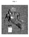
- FIG. 1 illustrates the external structure of a robot apparatus to which a force control according to an embodiment of the present invention is applied
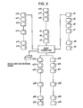
- FIG. 2 illustrates the electrical connection topology of the robot apparatus shown in FIG. 1 ;
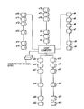
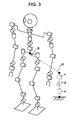
- FIG. 3 illustrates the degree-of-freedom model of the joints of the robot apparatus shown in FIG. 1 ;
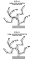
- FIG. 4 illustrates a normal route for computing force information from a terminal end to a base of a multi-link apparatus installed on a floor
- FIG. 5 illustrates a normal route for computing acceleration information from a base to a terminal end of a multi-link apparatus installed on a floor
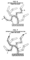
- FIG. 6 illustrates an optimized route for computing the force information from a terminal end to a base of a multi-link apparatus installed on a floor
- FIG. 7 illustrates an optimized route when accelerations occurring at given points of a multi-link apparatus installed on a floor are computed from a base to a terminal end;
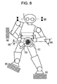
- FIG. 8 illustrates the constraint conditions that should be taken into account when a legged mobile robot carries out the fullbody motion
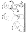
- FIGS. 9A-9C illustrate objects on which physical interactions, such as collisions and contacts, are applied.
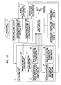
- FIG. 10 is a schematic illustration of the functional structure of an apparatus for calculating an inverse operational space inertia matrix on the basis of a method according to an embodiment of the present invention
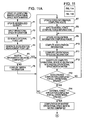
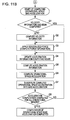
- FIG. 11 is a flow chart illustrating the procedure for computing an inverse operational space inertia matrix and an operational-space bias acceleration in the apparatus having the functional structure shown in FIG. 10 ;
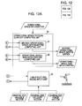
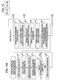
- FIG. 12 is a schematic illustration of the functional structure of an apparatus that computes elements of an inverse operational space inertia matrix in parallel;
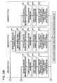
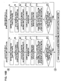
- FIG. 13 is a flow chart illustrating the procedure for computing an inverse operational space inertia matrix performed by an apparatus for computing an inverse operational space inertia matrix and a bias acceleration in parallel;
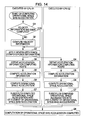
- FIG. 14 is a flow chart illustrating the procedure for computing an operational space bias acceleration performed by an apparatus for computing an inverse operational space inertia matrix and a bias acceleration in parallel;
- FIG. 15 illustrates a configuration in which the elements in individual columns of the inverse operational space inertia matrix are computed in parallel
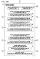
- FIG. 16 is a flow chart illustrating the procedure for computing the inverse operational space inertia matrix performed by the configuration of the apparatus shown in FIG. 15 ;
- FIG. 17 illustrates the structure of a multi-axis robot
- FIG. 18 is a diagram in which a force corresponding to one operational space acts on the centers of gravity of all of links.
- These embodiments of the present invention relate to an operation control apparatus for carrying out precise control of the velocity and acceleration while flexibly responding to an external force in the operation performed by a legged mobile robot having a complicated structure to carry out a task while interacting with the external world.
- the inverse operational space inertia matrix that is a physical quantity important for operating a robot under the force control is computed at high speed, and therefore, real-time force control can be achieved.
- FIG. 1 illustrates the external structure of a robot apparatus to which the force control according to an embodiment of the present invention is applied.
- Two legs serving as moving means are connected to a pelvis portion.
- an upper body is connected to the pelvis portion via a waist joint.
- Two arms are connected to the upper body.
- a head is also connected to the upper body via a neck joint.
- Each of the left and right legs has three degrees of freedom at the hip joint, one degree of freedom at a knee joint, and two degrees of freedom at an ankle joint. That is, each of the left and right legs totally has six degrees of freedom.
- each of the left and right arms has three degrees of freedom at a shoulder joint, one degree of freedom at an elbow joint, and two degrees of freedom at a wrist joint. That is, each of the left and right arms totally has six degrees of freedom.
- Each of the neck joint and the waist joint has three degrees of freedom about the X, Y, and Z axes.
- An actuator for driving each of joint shafts includes, for example, a DC brushless motor, a speed reducer, and a position sensor for detecting the rotational position of an output shaft of the speed reducer.
- These joint driving actuators are connected to a host computer for performing total control of the operation of the robot apparatus.
- the joint driving actuators can receive the position control target values from the host computer and can send the current output torques, the angles of the joints, and the angular velocities of the joints to the host computer.
- FIG. 2 illustrates the electrical connection topology of the robot apparatus shown in FIG. 1 .
- FIG. 3 illustrates the degree-of-freedom model of the joints of the robot apparatus shown in FIG. 1 .
- the body of the robot apparatus includes waist joint actuators a 1 , a 2 , and a 3 for three axes and neck joint actuators a 16 , a 17 , and a 18 for three axes. These joint actuators are connected to the host computer in series. Each of the joint actuators receives the position control target value from the host computer via a serial cable and sends the current output torque, the angle of the joint, and the angular velocity of the joint to the host computer.
- the left arm of the robot apparatus includes shoulder joint actuators a 4 , a 5 , and a 6 for three axes and an elbow joint actuator a 7 for one axis, and two wrist joint actuators a 8 and a 9 for two axes. These joint actuators are connected to the host computer in series.
- the right arm of the robot apparatus includes shoulder joint actuators a 10 , a 11 , and a 12 for three axes and an elbow joint actuator a 13 for one axis, and two wrist joint actuators a 14 and a 15 for two axes. These joint actuators are also connected to the host computer in series.
- the left leg of the robot apparatus includes hip joint actuators a 19 , a 20 , and a 21 for three axes, a knee actuator a 22 for one axis, and two ankle joint actuators a 23 and a 24 for two axes. These joint actuators are connected to the host computer in series.
- the right leg of the robot apparatus includes hip joint actuators a 25 , a 26 , and a 27 for three axes, a knee actuator a 28 for one axis, and two ankle joint actuators a 29 and a 30 for two axes. These joint actuators are connected to the host computer in series.
- Each of the actuators a 1 to a 30 used for individual joints includes, for example, a DC brushless motor, a speed reducer, and a position sensor for detecting the rotational position of an output shaft of the speed reducer. These actuators drivingly rotate in accordance with the position control target values externally provided and output the current output torques, the angles of the joints, and the angular velocities of the joints.
- This type of joint actuator is described in, for example, Japanese Unexamined Patent Application Publication No. 2004-181613 that has been already assigned to the present applicant.
- a biped mobile robot can be expressed as an open link tree structure having a pelvis B as a base.
- q denotes a generalized variable of the entire robot.
- ⁇ denotes the generalized force corresponding to the generalized variable q.
- the elements corresponding to ⁇ and p 0 are zero (since actuators that generate the forces are not present).
- the element corresponding to ⁇ is equal to a force generated by the actuators that drive individual joints.
- H denotes an inertia matrix of the entire robot and b denotes the force of gravity or the Coriolis force.
- f denotes an external force.
- J denotes the Jacobian matrix for associating the velocity generated in the external force acting direction with the generalized velocity which is the temporal differentiation of the generalized variable q.
- the present embodiment provides the solution of the inverse operational space inertia matrix that satisfies the requirement for a high-speed computation and the reduction of the computational load by applying a forward dynamics calculation used for obtaining the generalized acceleration (joint acceleration) from the generalized force (joint force) of a link structure.
- the forward dynamics calculation is a core calculation used for a kinetic simulation. Research for speeding up the forward dynamics calculation has been intensely carried out. In addition, several methods for performing the forward dynamics calculation in parallel have been developed.
- the present embodiment provides a highly efficient solution of an inverse operational space inertia matrix by using the excellent forward dynamics calculation.
- Obtaining the left-hand side from the right-hand side of equation (7) means obtaining the acceleration in the operational space when an external force, a generalized force, the force of gravity, and a force relating to a velocity product (such as the Coriolis force) are exerted on the operational space.
- this calculation can be considered to be one type of forward dynamics calculation.
- forward dynamics calculation FWD a joint model defining a kinetic model of a link structure, the velocities of the joints, a joint torque ⁇ defining a generalized force, the acceleration g due to gravity, and an external force f are used as parameters.
- an acceleration generated at any point of a link structure can be obtained from the information about forces that are exerted on a link structure (such as the generalized variable q corresponding to the kinetic model of the link structure, a generalized force ⁇ , the force g of gravity, and an external force f).
- a link structure such as the generalized variable q corresponding to the kinetic model of the link structure, a generalized force ⁇ , the force g of gravity, and an external force f.
- the ith column of the inverse operational space inertia matrix ⁇ ⁇ 1 can be obtained. Accordingly, by computing the following equation (10) for every row i, the inverse operational space inertia matrix ⁇ ⁇ 1 can be obtained.
- i th column of ⁇ ⁇ 1 FWD ( q, 0,0,0, e i ) (10)
- a method for constructing a computing apparatus for computing the inverse operational space inertia matrix ⁇ ⁇ 1 and the associated operational-space bias acceleration c is described in detail below with reference to an example of a specific forward dynamics calculation.
- the forward dynamics calculation used to be carried out using an inverse dynamics calculation (a calculation for obtaining a force from acceleration).
- the computational amount O(N 3 ) is needed. If the number of degrees of freedom increases, the computational amount also increases. Research has advanced in recent years, and therefore, the computational amount O(N) can be achieved using a single central processing unit (CPU) and the computational amount O(log(N)) can be achieved using multiple CPUs in parallel.
- a method for constructing a calculation model using a single CPU (O(N)) and the articulated body method is employed.
- the articulated body method is described in, for example, “The calculation of robot dynamics using articulated-body inertias”, The International Journal of Robotics Research, vol. 2, no. 1, pp. 13-30, 1983.
- the articulated body method is divided into the following four steps: an inertia information computing step, a velocity information computing step, a force information computing step, and an acceleration information computing step.
- the force information can be obtained by computing the following equations (14) and (15) for every bias force P A i of a link from the terminal end to the base of the robot apparatus.
- FIG. 4 illustrates a normal route for computing the force information from the terminal end to the base of a multi-link apparatus installed on a floor.
- the acceleration information can be obtained by computing the following equations (16) and (17) for every acceleration a i of a link from the base to the terminal end of the robot apparatus.
- FIG. 5 illustrates a normal route for computing the acceleration information from the base to the terminal end of a multi-link apparatus installed on a floor.
- ⁇ umlaut over (q) ⁇ i ( S T i I A i S i ) ⁇ 1 ⁇ i ⁇ S T i ( I A i ⁇ p +p i ) ⁇ (16)
- ⁇ i ⁇ p + ⁇ dot over (S) ⁇ i ⁇ dot over (q) ⁇ i +S i ⁇ umlaut over (q) ⁇ i (17)
- the acceleration occurring at any location in any direction of a link structure can be obtained when any force is applied to the link structure.
- a link structure such as a legged mobile robot
- the inertia information can be obtained by computing equation (12) for every link from the terminal end to the base of a link structure.
- equation (12) the inertia information does not change unless the orientation of the link structure (i.e., the joint value) changes. Since the joint value q, which is a generalized variable, is common for the inverse operational space inertia matrix according to equation (10) and the operational-space bias acceleration according to equation (11) and does not change, only one calculation of equation (12) for calculating the inertia information is needed.
- Equation (13) should be performed only when the operational-space bias acceleration is computed according to equation (11).
- FIG. 6 illustrates an optimized route for computing the force information from the terminal end to the base when forces are applied to points A, B, and C of a multi-link apparatus installed on a floor. As shown in FIG. 6 , computation for a link that is not on the route from the point of application of force to the base is eliminated.
- p A i 0 if i is not present on the route for computing the force information.
- g 0 in the term containing the acceleration due to gravity.
- FIG. 7 illustrates an optimized route when accelerations occurring at three points D, E, and F of a multi-link apparatus installed on a floor are computed from the base to the terminal end.
- the links with cross-hatchings are the links on the route used for computing the force information when forces are applied to the points A, B, and C, as shown in FIG. 6 .
- substitution of the value of p A i into a link for which the force information computation has been executed is performed and this acceleration calculation is performed.
- the acceleration calculation is eliminated.
- the acceleration of a point G shown in FIG. 7 is calculated, the acceleration does not change unless the force information is changed. Accordingly, in FIG. 7 , the point F for which the acceleration calculation has already been executed is considered to be a starting point.
- the acceleration can be additionally updated along the route from the point F to the point G.
- equation (11) for computing the operational-space bias acceleration there are no terms that can be eliminated from equations (16) and (17).
- the acceleration information computation is not necessary for all of the links.
- the acceleration calculation is needed only on the route from the base to the link for calculating the acceleration.
- the acceleration calculation can be added from the link that is the closest to the link for which the acceleration calculation has been executed, as in the calculation for the inverse operational space inertia matrix.
- the forward dynamics calculation can be applied to the case where one operational space relates to the positions and orientations of a plurality of points of a structure.
- the inverse operational space inertia matrix can be calculated at high speed.
- Step 1 computing inertia information by carrying out computation of equation (12) for all of links from the terminal end to the base;
- Step 2 regarding the calculation for velocity information to be unnecessary when calculating the inverse operational space inertia matrix
- Step 3 computing force information by carrying out computation of equation (20), from the terminal end to the base, for a link in routes from the point B to the base and from the point C to the base when a unit force is applied to the points B and C;
- Step 4 computing acceleration information by carrying out computation of equations (21) and (22) from the terminal end to the base (note that the acceleration g due to gravity at the starting point is set to zero);
- Step 5 applying equation (18) to the points B and C and computing the difference between the results so as to obtain the inverse operational space inertia matrix relating to the relative movement between the points B and C (note that the acceleration g due to gravity is set to zero).
- a procedure for computing the operational-space bias acceleration is as follows:
- Step 1 regarding update of the inertia information to be unnecessary since the inertia information has been obtained in the inverse operational space inertia matrix calculation;
- Step 2 computing velocity information by carrying out computation of equation (13) for all of links from the base to the terminal end;
- Step 3 computing force information by carrying out computation of equation (14) for all of links from the terminal end to the base when a generalized force ⁇ is applied to all of the links;
- Step 4 computing acceleration information by carrying out computation of equations (16) and (17) from the base to the points B and C;
- Step 5 applying equation (18) to the points B and C and calculating the difference between the results so as to obtain the bias acceleration relating to the relative movement between the points B and C.
- the inverse operational space inertia matrix and the bias acceleration can be efficiently obtained even when one operational space relates to the positions and orientations of a plurality of points of the structure.
- the inverse operational space inertia matrix for the operational space of the center of gravity can be also efficiently calculated.
- the barycentric velocity is defined as follows:
- x . g ⁇ m i M ⁇ x . g i ( 23 )
- x g denotes the center of gravity of the link structure
- X gi denotes the center of gravity of a rigid body i
- M denotes the mass of the entire link structure
- m i denotes the mass of the rigid body i.
- the transposed Jacobian matrix of the center of gravity can be defined as follows:
- J g T ⁇ m i M ⁇ J g i T ( 24 )
- J g denotes the center-of-gravity Jacobian of the entire link structure
- J gi denotes the center-of-gravity Jacobian of a rigid body i.
- a unit force can be applied to the center of gravity of the structure including a plurality of rigid links shown in FIG. 18 by applying an m i /M unit force to each rigid body.
- the inverse operational space inertia matrix can be obtained by computing the acceleration occurring at the center of gravity using the following equation:
- Step 1 computing inertia information by carrying out computation of equation (12) for all of links from the terminal end to the base;
- Step 2 regarding velocity information to be unnecessary when the inverse operational space inertia matrix is computed
- Step 3 computing force information by carrying out computation of equation (20) for all of links from the terminal end to the base when an m i /M unit force (in a direction of the operational space) is applied to all of the links, as shown in FIG. 18 ;
- Step 4 computing acceleration information by carrying out computation of equations (21) and (22) from the base to the points B and C (note that the acceleration due to gravity at the starting point is set to zero);
- Step 5 applying equation (18) to the center of gravity of each rigid body i to calculate the acceleration of the center of gravity X gi and calculating the acceleration occurring at the center of gravity of the entire link structure so as to obtain the inverse operational space inertia matrix (note that the acceleration due to gravity is set to zero).
- the inverse operational space inertia matrix can be efficiently obtained even when a plurality of forces should be applied at the same time.
- a unit force can be applied to the operational space of the angular momentum by applying a force obtained by multiplying the operational space of the angular momentum by a cross product [ ⁇ m i (X gi ⁇ X g ) ⁇ ] and a moment obtained by multiplying the operational space of the angular momentum by I i to the center of gravity of each rigid body.
- the inverse operational space inertia matrix can be efficiently obtained even when a plurality of forces and moments should be applied at the same time.
- FIG. 8 illustrates the constraint conditions that should be taken into account when a legged mobile robot carries out the fullbody motion.
- Sections (a), (b), and (c) of FIG. 8 indicate constraints relating to the interface with the environment.
- Section (d) indicates a constraint relating to the self-interference. These constraints define the operational spaces in directions of a vertical reaction force and a frictional force.
- Section (e) indicates a constraint relating to the available range of movement of a joint. This constraint defines an operational space in the rotational direction of the joint.
- Section (f) indicates a constraint relating to the motion of the wrist with respect to an object. This constraint defines an operational space in the direction of the position of the end-effector relative to the object and the orientation.
- Section (g) indicates a constraint for maintaining head cameras horizontal. This constraint defines an operational space relating to the orientation of the head in an absolute space.
- Section (h) indicates a constraint relating to the center of gravity. This constraint defines an operational space relating to the center of gravity.
- Section (i) indicates a constraint relating to the angular momentum. This constraint defines an operational space relating to the angular momentum.
- f Ni and f Fi that appear in equations (30) and (31), respectively, denote the external force and the frictional force in the normal direction at a point i of application of force caused by the constraint relating to the interface with an external world, as shown by the sections (a), (b), and (c) of FIG. 8 .
- ⁇ i denotes the coefficient of friction at the point i of application of force.
- Equations (29) to (30) are known as a linear complementarity problem. If the inverse operational space inertia matrix ⁇ ⁇ 1 and the operational-space bias acceleration c are known, the acceleration of the variable x and the force f that satisfy the conditions can be determined by solving this linear complementarity problem.
- the mathematical method for solving a linear complementarity problem is described in, for example, “Fast Contact Force Computation for Nonpenetrating Rigid Bodies,” Proceedings of SIGGRAPH '94, pp. 23-34, 1994. Therefore, a description of the method is not repeated here.
- ⁇ null denotes a joint force provided using a constraint with a priority that is lower than the priority of the constraint indicated by f.
- J # denotes one type of generalized inverse matrix of J.
- the method for computing the inverse operational space inertia matrix is applicable to many technical fields including kinetic simulation, computer animation, posture editing, and external force estimation in addition to the force control of a robot.
- this method is also effective when a plurality of objects coexist in a virtual environment and a real-time kinetic simulation is carried out in order to reconstruct physical interactions (e.g., collisions and contacts) among the objects or when a plurality of objects coexist in a virtual environment and the objects are operated.
- Kinetic calculation in a kinetic simulation can be performed by applying a force between objects to the forward dynamics calculation (see Non-patent document 2) as an external force.
- FIGS. 9A-C are diagrams illustrating physical interactions (e.g., collisions and contacts) occurring among objects.
- collisions between virtual objects are detected at points (a) and (b).
- the external force can be determined by solving the linear complementarity problem shown by equations (29) to (31) so as to achieve a reaction having a restitution coefficient specified for the objects and an appropriate friction.
- an operational space is defined for the points (a) and (b) in directions of a vertical reaction force and a frictional force and, subsequently, the inverse operational space inertia matrix ⁇ ⁇ 1 and the operational-space bias acceleration c are computed at high speed.
- this external force can be precisely obtained in a short time. Accordingly, even for a complicated environment, a precise kinetic simulation can be performed in real time.
- FIG. 9B illustrates an example in which a haptic device D 1 is connected to such a real-time kinetic simulation environment, the position of an object (proxy) P 1 in the virtual environment is changed on the basis of the position of the top end of the haptic device D 1 , and a force acting on the object P 1 is fed back to the haptic device D 1 .
- an operational space (c) relating to the relative position error is defined so that the position of the object P 1 is equal to the position instructed by the haptic device D 1 .
- an operational space (d) relating to collision between the object P 1 and another object is defined in directions of a vertical reaction force and a frictional force.
- FIG. 9C illustrates the configuration that can impose constraints (L 1 to L 4 ) relating to the position and the orientation on a variety of points of an object (e.g., a human figure) in the virtual environment in addition to the configuration shown in FIG. 9B .
- the constraints relating to the position and the orientation can be represented in the form of an equality expression as shown in equation (29).
- the operational space can be defined by setting three directions parallel to the world coordinate system at a position at which the constraints relating to the position and the orientation are defined. Additionally, by applying the constraints relating to the position and the orientation to a relative position and orientation between an object P 2 and another object so as to define the operational space (e) at that position and by feeding back, to a haptic device P 2 , a force acting on the object P 2 when a predetermined position of an object in the virtual environment is pulled or twisted, the sensation of the reaction force to the pull or the twist can be precisely provided.
- FIG. 10 is a schematic illustration of the functional structure of an apparatus for calculating the inverse operational space inertia matrix on the basis of the method according to the present embodiment.
- the apparatus includes a link-structure-model input unit 10 , a forward dynamics calculating unit 20 , and an operational space physical quantity computing unit 30 .
- This apparatus is realized by running a software program for performing the forward dynamics calculation and the operational space quantity calculation on a widely used computer system (e.g., a personal computer).
- the link-structure-model input unit 10 receives and holds the mass, the inertia, the center of gravity, geometric dimensions, and joint attributes (friction and inertia) of each of rigid bodies of a link structure, a method for connecting the rigid bodies, generalized variables (joint values), a generalized velocity (joint velocity), a generalized force (joint force), and variables required for the forward dynamics calculation (e.g., articulated body inertia information, velocity information, force information, and acceleration information). If any one of the generalized variables, the generalized velocity, and the generalized force is changed, the link-structure-model input unit 10 reflects the change to a held link structure model.
- the forward dynamics calculating unit 20 includes an inertia information computing unit 21 , a velocity information computing unit 22 , and an inverse-operational-space-inertia-matrix force information computing unit 23 , an inverse-operational-space-inertia-matrix acceleration information computing unit 24 , a bias-acceleration force information computing unit 25 , and a bias-acceleration acceleration information computing unit 26 .
- the forward dynamics calculating unit 20 provides forward dynamics calculation elements that are necessary for computing the inverse operational space inertia matrix ⁇ ⁇ 1 and the bias acceleration c.
- the inertia information computing unit 21 computes inertia information (articulated body inertia) for all of links from the terminal end to the base of the link structure on the basis of equation (12). The computation result is stored in the link-structure-model input unit 10 . The computation of the inertia information is carried out only once when the generalized variable is changed.
- the velocity information computing unit 22 computes the velocities of all the links from the base to the terminal end of the link structure on the basis of equation (13). The computation result is stored in the link-structure-model input unit 10 . The computation of the velocity information is carried out only once when the generalized variable or the generalized velocity is changed.
- the inverse-operational-space-inertia-matrix force information computing unit 23 computes force information about rigid bodies on a route between a point of application of an external force and the base on the basis of equation (20).
- the external force is provided by the operational space physical quantity computing unit 30 .
- a force information computing route is determined and, subsequently, the force information is computed from the point of application of the external force to the base.
- the computed force information and the computing route are stored in the link-structure-model input unit 10 .
- the inverse-operational-space-inertia-matrix acceleration information computing unit 24 computes acceleration information about rigid bodies on a route between the acceleration computing point and the base on the basis of equations (21) and (22) and, subsequently, computes the acceleration at the acceleration computing point using equation (18). It is noted that the acceleration due to gravity is set to zero.
- the acceleration computing point is provided by the operational space physical quantity computing unit 30 .
- the acceleration information computing route is determined and, subsequently, the computation is carried out from the base to the acceleration computing point.
- the rigid body for which the computation has been carried out is stored in the link-structure-model input unit 10 . This stored rigid body serves as a starting point of the calculation of acceleration of the next acceleration computing point.
- the computation result of the acceleration information is delivered to the operational space physical quantity computing unit 30 .
- the bias-acceleration force information computing unit 25 computes equations (14) and (15) under the conditions in which no external forces are applied and, subsequently, computes force information from the terminal end to the base.
- the computed force information is stored in the link-structure-model input unit 10 .
- the bias-acceleration acceleration information computing unit 26 computes acceleration information about a rigid body on a route between the acceleration computing point and the base on the basis of equations (16) and (17) and, subsequently, computes the acceleration of the acceleration computing point using equation (18).
- the acceleration computing point is provided by the operational space physical quantity computing unit 30 .
- the acceleration information computing route is determined.
- the computation is carried out from the base to the acceleration computing point.
- the rigid body for which the computation has been carried out is stored in the link-structure-model input unit 10 . That rigid body serves as a starting point of the calculation of acceleration of the next acceleration computing point.
- the computation result of the acceleration information is delivered to the operational space physical quantity computing unit 30 .
- the operational space physical quantity computing unit 30 includes an inverse-operational-space-inertia-matrix computing unit 31 and an operational-space-bias-acceleration computing unit 32 .
- the operational space physical quantity computing unit 30 computes the inverse operational space inertia matrix and the operational-space bias acceleration by repeatedly using the forward dynamics calculation.
- the inverse-operational-space-inertia-matrix computing unit 31 repeatedly computes equation (10) so as to determine each of the columns i of the inverse operational space inertia matrix ⁇ ⁇ 1 .
- the inverse-operational-space-inertia-matrix computing unit 31 uses the computation results from the inertia information computing unit 21 , the inverse-operational-space-inertia-matrix force information computing unit 23 , and the inverse-operational-space-inertia-matrix acceleration information computing unit 24 .
- the inertia information is updated only when the generalized variable is changed.
- the point of application of the external force and the acceleration measurement point are determined on the basis of the operational space information provided by a user.
- the accelerations occurring at the acceleration measurement points corresponding to all of the operational spaces are computed (i.e., the inverse-operational-space-inertia-matrix acceleration information is computed) with an external force for one operational space being applied (i.e., after the inverse-operational-space-inertia-matrix force information is computed).
- the acceleration occurring in each operational space is computed on the basis of the operational space information. This computation is repeated until the inverse operational space inertia matrix ⁇ ⁇ 1 is achieved.
- the operational-space-bias-acceleration computing unit 32 computes equation (11) so as to determine the operational space bias acceleration. To compute equation (11), the operational-space-bias-acceleration computing unit 32 uses the computation results from the inertia information computing unit 21 , the velocity information computing unit 22 , the inverse-operational-space-inertia-matrix force information computing unit 23 , the inverse-operational-space-inertia-matrix acceleration information computing unit 24 .
- the inertia information is updated only when the generalized variable is changed.
- the acceleration measurement points are determined on the basis of the operational space information provided by a user.
- the accelerations occurring at the acceleration measurement points corresponding to all of the operational spaces are computed (i.e., the bias-acceleration acceleration information is computed) with the generalized force, the force of gravity, and a velocity product being applied (i.e., after the bias-acceleration force information is computed).
- the acceleration occurring in each operational space is computed on the basis of the operational space information so that the operational-space bias acceleration c can be obtained.
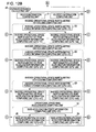
- FIG. 11 is a flow chart illustrating the procedure for computing the inverse operational space inertia matrix and the operational-space bias acceleration performed by an apparatus having the functional structure shown in FIG. 10 .
- steps P 1 through P 14 execute the processing for obtaining the inverse operational space inertia matrix
- steps Q 1 through Q 8 execute the processing for obtaining the operational-space bias acceleration.
- step P 1 the generalized variable, the generalized velocity, and the generalized force are set in the link structure model.
- step P 2 information about the operational space to be computed is acquired from the user.
- a data structure for storing information about each type of operational space e.g., the direction in which a force is applied to the specific portion of a rigid body, the relative displacement between two rigid bodies, and the barycentric velocity
- the list of the data structures is input.
- a list of external forces corresponding to the operational spaces is generated from the information about the operational spaces received at step P 2 . It is noted that a plurality of external forces may correspond to one operational space.
- a list of acceleration measurement points corresponding to the operational spaces is generated from the information about the operational spaces received at step P 2 . It is noted that a plurality of acceleration measurement points may correspond to one operational space.
- the articulated body inertia for all of the rigid bodies is computed by the inertia information computing unit 21 using equation (12) unless the articulated body inertia has been updated.
- a set of the external forces is retrieved from the external force list generated at step P 3 one by one so that a force information computing route between the point of application of an external force and the base is generated.
- the generated route is stored in the link structure model.
- step P 8 force information about each of rigid bodies with the external forces extracted at step P 7 being applied is computed by the inverse-operational-space-inertia-matrix force information computing unit 23 on the basis of equation (20).
- a set of the acceleration measurement points is retrieved from the acceleration measurement point list generated at step P 4 one by one so that an acceleration information computing route between the acceleration measurement point and the closest rigid body for which the acceleration information has been computed is generated.
- the generated route is stored in the link structure model.
- step P 10 the acceleration at the acceleration measurement point extracted at step P 9 is computed by the inverse-operational-space-inertia-matrix acceleration information computing unit 24 on the basis of equations (21) and (22).
- the operational space acceleration is computed from the acceleration at the acceleration measurement point obtained at step P 10 .
- the difference in acceleration between the points B and C is computed.
- the inverse-operational-space-inertia-matrix computing unit 31 substitutes the operational space acceleration computed by the inverse-operational-space-inertia-matrix acceleration information computing unit 24 at step P 11 into a predetermined position of the inverse operational space inertia matrix (the position of an ith column and a jth row when i denotes the index of the external force and j denotes the index of the acceleration).
- step P 13 it is determined whether the acceleration computation is performed for all the acceleration measurement points generated at step P 4 . If the acceleration computation has not been completed, the processing returns to step P 9 , where the acceleration at another acceleration measurement point is computed under the same external force application conditions.
- step P 14 it is determined whether all the applications of external force generated at step P 3 have been completed. If all the applications of external force have not been completed, the processing returns to step P 7 , where another external force is applied.
- the inverse operational space inertia matrix By sequentially performing the above-described processing on all the sets of external forces and all the sets of acceleration measurement points, the inverse operational space inertia matrix can be obtained. It should be noted that, since the inverse operational space inertia matrix is a symmetric matrix, the above-described processing can only be carried out for the entries of indices i ⁇ j (or i ⁇ j).
- the velocity information computing unit 22 computes velocity information about all of the rigid bodies only when the velocity information is not updated.
- the bias-acceleration force information computing unit 25 computes equations (14) and (15) under the conditions in which no external forces are applied.
- force information about each rigid body with the generalized force, the force of gravity, and the force based on the velocity product being applied is computed.
- a set of acceleration measurement points is retrieved from the acceleration measurement point list generated at step P 4 one by one so that an acceleration information computing route between the acceleration measurement point and the closest rigid body for which the acceleration information computation has been executed is generated.
- the generated route is stored in the link structure model.
- the bias-acceleration acceleration information computing unit 26 computes the acceleration information about a rigid body on the route between the acceleration measurement point and the base on the basis of equations (16) and (17). Subsequently, the acceleration at the acceleration measurement point extracted at step Q 4 is computed using equation (18).
- the operational-space-bias-acceleration computing unit 32 solves equation (11) so as to compute the operational-space bias acceleration from the acceleration at the acceleration measurement point computed at step Q 5 .
- equation (11) the difference in acceleration between the points B and C is computed.
- the operational space acceleration computed at step Q 6 is substituted into a predetermined position of the operational space bias acceleration vector (the position of the jth element of the vector when j denotes the index of the acceleration).
- step Q 8 it is determined whether the acceleration computation is performed for all the acceleration measurement points generated at step P 4 . If the acceleration computation has not been completed, the processing returns to step Q 4 , where the acceleration at another acceleration measurement point is computed.
- the operational-space bias acceleration can be obtained.
- the above-described methods for computing the inverse operational space inertia matrix and the operational-space bias acceleration can be further sped up by executing the methods on a parallel computer known as a grid computer or a cluster PC.
- a parallel computer known as a grid computer or a cluster PC.
- the inverse operational space inertia matrix is an M ⁇ M square matrix
- each of the elements of the matrix can be independently computed by using different CPUs.
- the operational-space bias acceleration is a vector having M elements. Each element of the operational-space bias acceleration vector can also be independently computed by using different CPUs.
- FIG. 10 illustrates the functional structure of an apparatus for computing the inverse operational space inertia matrix and the operational-space bias acceleration on the basis of the method according to the present embodiment
- FIG. 12 illustrates the modification of the apparatus that can process the method in parallel.
- the apparatus shown in FIG. 12 differs from the apparatus shown in FIG. 10 in the following three respects:
- the inverse-operational-space-inertia-matrix force information computing unit 23 in the forward dynamics calculating unit 20 is independently provided for each column of the inverse operational space inertia matrix, and therefore, computation for each column can be allocated to a different CPU;
- the inverse-operational-space-inertia-matrix acceleration information computing unit 24 is independently provided for each row of the inverse operational space inertia matrix in order to obtain elements in the same column in the row direction using the force information from the inverse-operational-space-inertia-matrix force information computing unit 23 provided for each column, and therefore, computation for each element can be allocated to a different CPU;
- the bias-acceleration acceleration information computing unit 26 is provided for each row in order to obtain elements of each row of the bias acceleration vector using the force information from the bias-acceleration force information computing unit 25 .
- FIG. 13 is a flow chart illustrating the procedure for computing the inverse operational space inertia matrix performed by the apparatus for computing the inverse operational space inertia matrix and the bias acceleration in parallel.
- FIG. 13 an example for computing a 2 ⁇ 2 inverse operational space inertia matrix is illustrated.
- step P 6 Even when the processing is parallelized, the same steps up to step P 6 are employed.
- Different CPUs executing the function of the inverse-operational-space-inertia-matrix force information computing unit 23 in the forward dynamics calculating unit 20 are independently provided for the first and second columns. That is, the computation of the force information at step P 7 is executed by different CPUs 11 and 12 for the two columns in parallel.
- a CPU for executing the function of the inverse-operational-space-inertia-matrix acceleration information computing unit 24 is provided for each of the first column and the second column so that calculation for individual elements after step P 9 can be performed by the different CPUs. That is, for the first column, the computation of the acceleration information using the inverse-operational-space-inertia-matrix force information computed by the CPU 11 is allocated to the independent CPUs 11 and 21 . Thus, two elements of the first column in the row direction are computed in parallel. Similarly, for the second column, the computation of the acceleration information using the inverse-operational-space-inertia-matrix force information computed by the CPU 12 is allocated to the independent CPUs 12 and 22 . Thus, two elements of the second column in the row direction are computed in parallel.
- FIG. 14 is a flow chart of illustrating the procedure for computing the operational-space bias acceleration performed by the apparatus for computing the inverse operational space inertia matrix and the bias acceleration in parallel. Like FIG. 13 , in FIG. 14 , an example for computing a 2 ⁇ 2 inverse operational space inertia matrix is illustrated.
- step Q 3 the generalized force is applied, i.e., the force information is computed.
- a CPU for executing the function of the bias-acceleration acceleration information computing unit 26 is provided for each row.
- the computation of the acceleration information after step Q 4 is performed in parallel by CPUs 01 and 02 that are provided for two rows.
- the apparatus by configuring the apparatus so as to compute the inverse operational space inertia matrix and the bias acceleration in parallel, the computation is performed for each element of the matrix or vector in parallel. Accordingly, the computation of all the elements can be completed within the computing time required for the computation of one element, and therefore, significant reduction of the total time can be achieved.
- FIG. 15 illustrates a configuration in which the elements in individual columns of the inverse operational space inertia matrix are computed in parallel.
- the difference between the configuration shown in FIG. 15 and that shown in FIG. 10 are as follows:
- the inverse-operational-space-inertia-matrix force information computing unit 23 is independently provided for each column of the inverse operational space inertia matrix so that the computations for individual columns can be allocated to different CPUs;
- the inverse-operational-space-inertia-matrix acceleration information computing unit 24 is provided for each column in order to compute the elements in the column in the row direction using the inverse-operational-space-inertia-matrix force information output from the inverse-operational-space-inertia-matrix force information computing unit 23 .
- the acceleration for the column is computed.
- FIG. 16 is a flow chart illustrating the procedure for computing the inverse operational space inertia matrix performed by the configuration of the apparatus shown in FIG. 15 .
- FIG. 15 an example for computing a 3 ⁇ 3 inverse operational space inertia matrix is illustrated.
- step P 6 Even when the processing is parallelized, the same steps up to step P 6 as those in FIG. 10 are employed (in step P 6 , the inertia information is computed).
- a CPU for executing the function of the inverse-operational-space-inertia-matrix force information computing unit 23 is independently provided for each of a first column to a third column in the forward dynamics calculating unit 20 . That is, the calculation of the force information at step P 7 is carried out in parallel by using different CPUs 1 to 3 provided for individual columns.
- the computation corresponding to the inverse-operational-space-inertia-matrix acceleration information computing unit 24 for the elements in a column in the row direction is repeatedly carried out using the CPUs 1 to 3 provided for individual columns. Each of the CPUs 1 to 3 computes the acceleration information for one column.
- the apparatus by configuring the apparatus so as to compute the inverse operational space inertia matrix and the bias acceleration in parallel, the computations are performed for individual columns of the matrix in parallel. Accordingly, the computation of all the elements can be completed within the computing time in proportion to the number of the columns of the inverse operational space inertia matrix, and therefore, the speed-up can be effectively achieved.
- the computing speed can be further increased by using the forward dynamics calculation algorithm for parallel processing (refer to, for example, “A Divide-and-Conquer Articulated-Body Algorithm for Parallel O(log(n)) Calculation of Rigid-Body Dynamics,” J. Robotics Research, vol. 18, no. 9, pp. 867-875, 1999).
Landscapes
- Engineering & Computer Science (AREA)
- Robotics (AREA)
- Mechanical Engineering (AREA)
- Manipulator (AREA)
- Management, Administration, Business Operations System, And Electronic Commerce (AREA)
Abstract
Description
{dot over (x)}=J{dot over (q)} (1)
Λ−1 =JH −1 J T (2)
where H denotes an inertia matrix for the joint space of the entire structure.
τ=H{umlaut over (q)}+b−J T f (3)
q=(α,p 0,θ)T (4)
{dot over (x)}=J{dot over (q)} (5)
Solution of Inverse Operational Space Inertia Matrix
τ=H{umlaut over (q)}+b−J T f (6)
where τ denotes the generalized force corresponding to the generalized variable q, b denotes the force of gravity or the Coriolis force, and f denotes an external force exerted on the operational space. Equation (6) can be rewritten as follows:
{umlaut over (x)}=Λ −1 f+c (7)
where c denotes the operational-space bias acceleration (the acceleration generated in an operational space when no external forces act on the operational space). The operational-space bias acceleration c is expressed as follows:
c=JH −1(τ−b)+{dot over (J)}{dot over (q)} (8)
{umlaut over (x)}=FWD(q,{dot over (q)},τ,g,f) (9)
ith column of Λ−1 =FWD(q,0,0,0,e i) (10)
c=FWD(q,{dot over (q)},τ,g,0) (11)
I A i =I i+ΣjεC(i) {I A j −I A j S j(S T j I A j S j)−1 S T j I A j} (12)
where Ii denotes the inertia of a link i, C(i) denotes the index set of child links of the link i, and Sj denotes a matrix indicating the number of degrees of freedom of motion of a joint of a link j.
Velocity Information Computing Step
v i =v p +S i {dot over (q)} i (13)
where vi denotes the velocity of a link i, p denotes an index of the parent link of the link i, Si denotes a matrix indicating the degree of motion freedom of the joint of the link i, and qi denotes the joint value of the link i.
Force Information Computing Step
p A i =v i ×I i v i−ΣkεF(i) f k+ΣjεC(i) {p j +I A j S j(S T j I A j S j)−1(τj S T j p j)} (14)
p i =p A i +I A i {dot over (S)} i {dot over (q)} i (15)
where fk denotes the kth external force in the link i, F(i) denotes the index set of external forces exerted on the link i, and τi denotes a joint force of the link i.
Acceleration Information Computing Step
{umlaut over (q)} i=(S T i I A i S i)−1{τi −S T i(I A iαp +p i)} (16)
αi=αp +{dot over (S)} i {dot over (q)} i +S i {umlaut over (q)} i (17)
{umlaut over (x)}n T(αi +g) (18)
a o =g (19)
p A i=−ΣkεF(i) f k+ΣjεC(i) {p j −I A j S j(S T j I A j S j)−1 S T j p A j} (20)
{umlaut over (q)} i=−(S T i I A i S i)−1 S T i(I A iαp +p A i) (21)
αi=αp +S i {umlaut over (q)} i (22)
where xg denotes the center of gravity of the link structure, Xgi denotes the center of gravity of a rigid body i, M denotes the mass of the entire link structure, and mi denotes the mass of the rigid body i.
where Jg denotes the center-of-gravity Jacobian of the entire link structure and Jgi denotes the center-of-gravity Jacobian of a rigid body i.
L=Σ{m i(x g −x g
where L denotes the angular momentum of the entire link structure and ωi denotes the angular velocity of a rigid body i.
J T L =Σ{J T g
where JL is the Jacobian matrix of the angular momentum of the entire link structure and Jωi denotes the Jacobian matrix of the angular velocity of a rigid body i.
{dot over (L)}=Σ{m i({dot over (x)} g −{dot over (x)} g
τ=J T f+(I−J # J)Tτnull (32)
Claims (48)
I i A =I i+ΣjεC(i) {I j A −I j A S j(S j T I j A S j)−1 S j T I j A},
v i =v p +S i {dot over (q)} i,
p i A =v i ×I i v i−ΣkεF(i) f k+ΣjεC(i) {p j +I j A S j(S j T I j A S j)−1(τj −S j T p j)}; and
p i =p i A +I i A {dot over (S)} i {dot over (q)} i,
{umlaut over (q)} i=(S i T I i A S i)−1{τi −S i T(I i Aαp +p i)}; and
αi=αp +{dot over (S)} i {dot over (q)} i +S i {umlaut over (q)} i; and
{umlaut over (x)}=n T(αi +g),
p i A=−ΣkεF(i) f k+ΣjεC(i) {p j −I j A S j(S j T I j A S j)−1 S j T p j A}.
{umlaut over (q)} i=−(S i T I i A S i)−1 S i T(I i Aαp +p i A); and
αi=αp +S i {umlaut over (q)} i.
{dot over (L)}=Σ{m i({dot over (x)} g −{dot over (x)} g
{dot over (L)}Σ{m({dot over (x)} g −{dot over (x)} g
Applications Claiming Priority (2)
| Application Number | Priority Date | Filing Date | Title |
|---|---|---|---|
| JP2005298090A JP4682791B2 (en) | 2005-10-12 | 2005-10-12 | Operation space physical quantity calculation device, operation space physical quantity calculation method, and computer program |
| JP2005-298090 | 2005-10-12 |
Publications (2)
| Publication Number | Publication Date |
|---|---|
| US20070083290A1 US20070083290A1 (en) | 2007-04-12 |
| US8140189B2 true US8140189B2 (en) | 2012-03-20 |
Family
ID=37911874
Family Applications (1)
| Application Number | Title | Priority Date | Filing Date |
|---|---|---|---|
| US11/544,052 Active 2030-01-25 US8140189B2 (en) | 2005-10-12 | 2006-10-06 | Apparatus and method for computing operational-space physical quantity |
Country Status (2)
| Country | Link |
|---|---|
| US (1) | US8140189B2 (en) |
| JP (1) | JP4682791B2 (en) |
Cited By (14)
| Publication number | Priority date | Publication date | Assignee | Title |
|---|---|---|---|---|
| US20090287354A1 (en) * | 2008-05-13 | 2009-11-19 | Samsung Electronics Co., Ltd | Robot and method of controlling cooperative work thereof |
| US20100179795A1 (en) * | 2007-06-20 | 2010-07-15 | Redon Stephane | Computer device for simulating a set of objects in interaction and corresponding method |
| US20110160907A1 (en) * | 2009-12-28 | 2011-06-30 | Honda Motor Co., Ltd. | Control device for robot |
| US20120010747A1 (en) * | 2010-01-04 | 2012-01-12 | Yasunao Okazaki | Robot, control device for robot, and control method of robot |
| US20120095598A1 (en) * | 2010-10-14 | 2012-04-19 | Sony Corporation | Control device for robot, control method and computer program |
| US20120310412A1 (en) * | 2011-05-30 | 2012-12-06 | Samsung Electronics Co., Ltd. | Robot and control method thereof |
| US9226796B2 (en) | 2012-08-03 | 2016-01-05 | Stryker Corporation | Method for detecting a disturbance as an energy applicator of a surgical instrument traverses a cutting path |
| US20160271799A1 (en) * | 2015-03-16 | 2016-09-22 | Fanuc Corporation | Trajectory generation apparatus for robot to generate trajectory including curved portion |
| US10031524B2 (en) * | 2015-12-02 | 2018-07-24 | Goertek Inc. | Method and device for controlling gait of biped robot |
| US10327849B2 (en) | 2015-11-11 | 2019-06-25 | Mako Surgical Corp. | Robotic system and method for backdriving the same |
| US10463440B2 (en) | 2012-08-03 | 2019-11-05 | Stryker Corporation | Surgical manipulator and method for resuming semi-autonomous tool path position |
| US11045958B2 (en) | 2012-08-03 | 2021-06-29 | Stryker Corporation | Surgical robotic system and method for commanding instrument position based on iterative boundary evaluation |
| US11202682B2 (en) | 2016-12-16 | 2021-12-21 | Mako Surgical Corp. | Techniques for modifying tool operation in a surgical robotic system based on comparing actual and commanded states of the tool relative to a surgical site |
| US12327071B1 (en) * | 2020-06-18 | 2025-06-10 | Nvidia Corporation | Internal solver for articulations in simulation applications |
Families Citing this family (23)
| Publication number | Priority date | Publication date | Assignee | Title |
|---|---|---|---|---|
| US8924021B2 (en) * | 2006-04-27 | 2014-12-30 | Honda Motor Co., Ltd. | Control of robots from human motion descriptors |
| US8223155B2 (en) * | 2007-04-27 | 2012-07-17 | Sony Corporation | Method for simulating large numbers of spherical bodies interacting |
| JP5109573B2 (en) | 2007-10-19 | 2012-12-26 | ソニー株式会社 | Control system, control method, and robot apparatus |
| JP2009099082A (en) * | 2007-10-19 | 2009-05-07 | Sony Corp | Dynamics simulation device, dynamics simulation method, and computer program |
| US9098766B2 (en) * | 2007-12-21 | 2015-08-04 | Honda Motor Co., Ltd. | Controlled human pose estimation from depth image streams |
| US8279227B2 (en) * | 2008-04-04 | 2012-10-02 | Sony Corporation | Method for detecting collisions among large numbers of particles |
| JP4715863B2 (en) | 2008-05-01 | 2011-07-06 | ソニー株式会社 | Actuator control apparatus, actuator control method, actuator, robot apparatus, and computer program |
| US20100332791A1 (en) * | 2009-06-25 | 2010-12-30 | Yu Xu | System, method, and computer-readable medium for optimizing processing of group-by queries featuring maximum or minimum equality conditions in a parallel processing system |
| US8170718B2 (en) * | 2008-12-18 | 2012-05-01 | GM Global Technology Operations LLC | Multiple priority operational space impedance control |
| US9256282B2 (en) * | 2009-03-20 | 2016-02-09 | Microsoft Technology Licensing, Llc | Virtual object manipulation |
| JP5506618B2 (en) * | 2009-12-28 | 2014-05-28 | 本田技研工業株式会社 | Robot control device |
| US8504208B2 (en) * | 2011-05-25 | 2013-08-06 | Honda Motor Co., Ltd. | Mobile object controller and floor surface estimator |
| FR2978844B1 (en) * | 2011-08-04 | 2014-03-21 | Aldebaran Robotics | ROBOT WITH ARTICULATIONS OF VARIABLE RIGIDITY AND METHOD OF CALCULATING SAID OPTIMIZED RIGIDITY |
| JP5982767B2 (en) | 2011-09-26 | 2016-08-31 | ソニー株式会社 | Exercise assistance device, exercise assistance method, computer program, and program recording medium |
| JP6104867B2 (en) * | 2014-09-19 | 2017-03-29 | Thk株式会社 | Robot upper body support structure |
| EP3552199A4 (en) * | 2016-12-13 | 2020-06-24 | Deepmotion, Inc. | Improved virtual reality system using multiple force arrays for a solver |
| CN109086466A (en) * | 2017-06-14 | 2018-12-25 | 深圳市祈飞科技有限公司 | Single leg multiaxis biped robot kinematics joint simulation method |
| CN111086001B (en) * | 2019-12-25 | 2021-09-14 | 广东省智能制造研究所 | State estimation method and system for multi-modal perception of foot robot |
| CN111872941B (en) * | 2020-08-06 | 2021-09-07 | 深圳市优必选科技股份有限公司 | Balance control method and device, humanoid robot and readable storage medium |
| CN113070880B (en) * | 2021-03-31 | 2022-09-09 | 深圳市优必选科技股份有限公司 | Motion control method and device, robot control equipment and readable storage medium |
| CN114137982B (en) * | 2021-11-29 | 2024-09-06 | 深圳市优必选科技股份有限公司 | Robot motion control method and device, robot control equipment and storage medium |
| US12049007B2 (en) * | 2022-03-01 | 2024-07-30 | Mitsubishi Electric Research Laboratories, Inc. | System and method for robust robotic manipulation using chance constrained optimization |
| KR102819245B1 (en) * | 2023-01-31 | 2025-06-11 | 한국로봇융합연구원 | Calculation device and method for performing bias acceleration calculation for Operational Space Formulation(OSF) |
Citations (17)
| Publication number | Priority date | Publication date | Assignee | Title |
|---|---|---|---|---|
| US5294873A (en) * | 1992-10-27 | 1994-03-15 | The United States Of America As Represented By The Administrator Of The National Aeronautics And Space Administration | Kinematic functions for redundancy resolution using configuration control |
| US5303384A (en) * | 1990-01-02 | 1994-04-12 | The United States Of America As Represented By The Administrator Of The National Aeronautics And Space Administration | High level language-based robotic control system |
| US5377310A (en) * | 1992-04-03 | 1994-12-27 | The United States Of America As Represented By The Administrator Of The National Aeronautics And Space Administration | Controlling under-actuated robot arms using a high speed dynamics |
| US5546508A (en) * | 1992-04-03 | 1996-08-13 | The United States Of America As Represented By The Administrator Of The National Aeronautics And Space Administration | Controlling flexible robot arms using high speed dynamics process |
| US20030018455A1 (en) * | 2000-11-02 | 2003-01-23 | Protein Mechanics, Inc. | Method for analytical jacobian computation in molecular modeling |
| JP2003231077A (en) | 2002-02-12 | 2003-08-19 | Univ Tokyo | Motion generation method of humanoid link system |
| US20030182518A1 (en) * | 2002-03-22 | 2003-09-25 | Fujitsu Limited | Parallel processing method for inverse matrix for shared memory type scalar parallel computer |
| US6738065B1 (en) * | 1999-08-10 | 2004-05-18 | Oshri Even-Zohar | Customizable animation system |
| US6750866B1 (en) * | 2000-04-21 | 2004-06-15 | Realistic Dynamics, Inc. | Method and system for dynamically filtering the motion of articulated bodies |
| JP2004167676A (en) | 2002-11-06 | 2004-06-17 | Sony Corp | Robot device, motion control device and motion control method of robot device |
| JP2004181613A (en) | 2002-03-18 | 2004-07-02 | Sony Corp | Robot device, device and method for controlling operation of legged locomotion robot, sensor system for legged locomotion robot, and moving body device |
| US20040210426A1 (en) * | 2003-04-16 | 2004-10-21 | Wood Giles D. | Simulation of constrained systems |
| US20050075755A1 (en) * | 2001-12-28 | 2005-04-07 | Honda Giken Kogyo Kabushiki Kaisha | Gait generation device for legged mobile robot |
| US20050209536A1 (en) * | 2001-06-29 | 2005-09-22 | Behzad Dariush | System and method of estimating joint loads using an approach of closed form dynamics |
| US20050209535A1 (en) * | 2001-06-29 | 2005-09-22 | Behzad Dariush | System and method of estimating joint loads in a three-dimensional system |
| US20050209534A1 (en) * | 2001-06-29 | 2005-09-22 | Behzad Dariush | System and method of predicting novel motion in a serial chain system |
| JP2007030054A (en) | 2005-07-22 | 2007-02-08 | Sony Corp | Robot device |
-
2005
- 2005-10-12 JP JP2005298090A patent/JP4682791B2/en not_active Expired - Fee Related
-
2006
- 2006-10-06 US US11/544,052 patent/US8140189B2/en active Active
Patent Citations (17)
| Publication number | Priority date | Publication date | Assignee | Title |
|---|---|---|---|---|
| US5303384A (en) * | 1990-01-02 | 1994-04-12 | The United States Of America As Represented By The Administrator Of The National Aeronautics And Space Administration | High level language-based robotic control system |
| US5377310A (en) * | 1992-04-03 | 1994-12-27 | The United States Of America As Represented By The Administrator Of The National Aeronautics And Space Administration | Controlling under-actuated robot arms using a high speed dynamics |
| US5546508A (en) * | 1992-04-03 | 1996-08-13 | The United States Of America As Represented By The Administrator Of The National Aeronautics And Space Administration | Controlling flexible robot arms using high speed dynamics process |
| US5294873A (en) * | 1992-10-27 | 1994-03-15 | The United States Of America As Represented By The Administrator Of The National Aeronautics And Space Administration | Kinematic functions for redundancy resolution using configuration control |
| US6738065B1 (en) * | 1999-08-10 | 2004-05-18 | Oshri Even-Zohar | Customizable animation system |
| US6750866B1 (en) * | 2000-04-21 | 2004-06-15 | Realistic Dynamics, Inc. | Method and system for dynamically filtering the motion of articulated bodies |
| US20030018455A1 (en) * | 2000-11-02 | 2003-01-23 | Protein Mechanics, Inc. | Method for analytical jacobian computation in molecular modeling |
| US20050209536A1 (en) * | 2001-06-29 | 2005-09-22 | Behzad Dariush | System and method of estimating joint loads using an approach of closed form dynamics |
| US20050209535A1 (en) * | 2001-06-29 | 2005-09-22 | Behzad Dariush | System and method of estimating joint loads in a three-dimensional system |
| US20050209534A1 (en) * | 2001-06-29 | 2005-09-22 | Behzad Dariush | System and method of predicting novel motion in a serial chain system |
| US20050075755A1 (en) * | 2001-12-28 | 2005-04-07 | Honda Giken Kogyo Kabushiki Kaisha | Gait generation device for legged mobile robot |
| JP2003231077A (en) | 2002-02-12 | 2003-08-19 | Univ Tokyo | Motion generation method of humanoid link system |
| JP2004181613A (en) | 2002-03-18 | 2004-07-02 | Sony Corp | Robot device, device and method for controlling operation of legged locomotion robot, sensor system for legged locomotion robot, and moving body device |
| US20030182518A1 (en) * | 2002-03-22 | 2003-09-25 | Fujitsu Limited | Parallel processing method for inverse matrix for shared memory type scalar parallel computer |
| JP2004167676A (en) | 2002-11-06 | 2004-06-17 | Sony Corp | Robot device, motion control device and motion control method of robot device |
| US20040210426A1 (en) * | 2003-04-16 | 2004-10-21 | Wood Giles D. | Simulation of constrained systems |
| JP2007030054A (en) | 2005-07-22 | 2007-02-08 | Sony Corp | Robot device |
Non-Patent Citations (10)
| Title |
|---|
| Aghili, F., Inverse and direct dynamics of constrained multibody systems based on orthogonal decomposition of generalized force, Sep. 2003, IEEE, 0-7803-7736-2/03, pp. 4035-4041. * |
| Anderson et al., Improved 'Order-N' Performance Algorithm for the Simulation of Constrained Multi-Rigid-Body Dynamic Systems, 2003, IEEE, Multibody System Dynamics, pp. 185-212. * |
| Chang et al., "Efficient Algorithm for Extended Operational Space Inertia Matrix," Proceedings of the IEEE International Conference on Intelligent Robots and Systems, pp. 350-355, (1999) (6 pages). |
| Featherstone et al., Robot Dynamics-Equations and Algorithms, Apr. 2000, Proceedings of the 2000 IEEE international Conference on Robotics and Automation, San Francisco, CA, 0-7803-5886-4/00, pp. 826-834. * |
| Jablokow et al, Alternate Forms of the Operational Space Inertia Matrix for the Dynamic Simulation of Complex Robot Systems, 2003, IEEE, 0-7803-7959-7/03, pp. 2225-2230. * |
| Jablokow, et al., "Alternate Forms of the Operational Space Inertia Matrix for the Dynamic Simulation of Complex Robot Systems," Proceedings of IEEE International Conference of System, Man, and Cybernetics, pp. 2225-2230, (2003) (6 pages). |
| Lilly, K., Efficient O(N) recursive computation of operational space inertia matrix, Sep./Oct. 2003, IEEE Transactions on Systems, Man. and Cybernetics, vol. 23, No. 5, pp. 1384-1391. * |
| Naudet et al., Forward Dynamics of Open-Loop Multibody Mechanisms Using an Efficient Recursive Algorithm Based on Canonical Momenta, 2003, IEEE, Multibody System Dynamics, pp. 45-59. * |
| Notification of Reasons for Refusal dated Jun. 7, 2010, from the Japanese Patent Office in corresponding Japanese patent Application No. 2005-298090, and English language translation thereof (13 pages). |
| Yamane et al., "Choreography of Humanoids Considering Physical Consistency Based on Operational Space Inverse Inertia," Japanese Society of Mechanical Engineers, Jun. 7, 2002, 2P1-K12(1)-(2) (2 pages). |
Cited By (35)
| Publication number | Priority date | Publication date | Assignee | Title |
|---|---|---|---|---|
| US20100179795A1 (en) * | 2007-06-20 | 2010-07-15 | Redon Stephane | Computer device for simulating a set of objects in interaction and corresponding method |
| US8489370B2 (en) * | 2007-06-20 | 2013-07-16 | Inria Institut National De Recherche En Informatique Et En Automatique | Computer device for simulating a set of objects in interaction and corresponding method |
| US20090287354A1 (en) * | 2008-05-13 | 2009-11-19 | Samsung Electronics Co., Ltd | Robot and method of controlling cooperative work thereof |
| US8560123B2 (en) * | 2008-05-13 | 2013-10-15 | Samsung Electronics Co., Ltd. | Robot and method of controlling cooperative work thereof |
| US20110160907A1 (en) * | 2009-12-28 | 2011-06-30 | Honda Motor Co., Ltd. | Control device for robot |
| US8532824B2 (en) * | 2009-12-28 | 2013-09-10 | Honda Motor Co., Ltd. | Control device for robot |
| US20120010747A1 (en) * | 2010-01-04 | 2012-01-12 | Yasunao Okazaki | Robot, control device for robot, and control method of robot |
| US8396594B2 (en) * | 2010-01-04 | 2013-03-12 | Panasonic Corporation | Robot, control device for robot, and control method of robot |
| US20120095598A1 (en) * | 2010-10-14 | 2012-04-19 | Sony Corporation | Control device for robot, control method and computer program |
| US8725293B2 (en) * | 2010-10-14 | 2014-05-13 | Sony Corporation | Control device for robot, control method and computer program |
| US20120310412A1 (en) * | 2011-05-30 | 2012-12-06 | Samsung Electronics Co., Ltd. | Robot and control method thereof |
| US8855821B2 (en) * | 2011-05-30 | 2014-10-07 | Samsung Electronics Co., Ltd. | Robot and control method thereof |
| US9795445B2 (en) | 2012-08-03 | 2017-10-24 | Stryker Corporation | System and method for controlling a manipulator in response to backdrive forces |
| US11672620B2 (en) | 2012-08-03 | 2023-06-13 | Stryker Corporation | Robotic system and method for removing a volume of material from a patient |
| US12364561B2 (en) | 2012-08-03 | 2025-07-22 | Stryker Corporation | Hand-held pendant for controlling a surgical robotic manipulator in a semi-autonomous mode |
| US12070288B2 (en) | 2012-08-03 | 2024-08-27 | Stryker Corporation | Robotic system and method for removing a volume of material from a patient |
| US9226796B2 (en) | 2012-08-03 | 2016-01-05 | Stryker Corporation | Method for detecting a disturbance as an energy applicator of a surgical instrument traverses a cutting path |
| US12004836B2 (en) | 2012-08-03 | 2024-06-11 | Stryker Corporation | Surgical manipulator and method of operating the same using virtual rigid body modeling preliminary |
| US11639001B2 (en) | 2012-08-03 | 2023-05-02 | Stryker Corporation | Robotic system and method for reorienting a surgical instrument |
| US11471232B2 (en) | 2012-08-03 | 2022-10-18 | Stryker Corporation | Surgical system and method utilizing impulse modeling for controlling an instrument |
| US10420619B2 (en) | 2012-08-03 | 2019-09-24 | Stryker Corporation | Surgical manipulator and method for transitioning between operating modes |
| US10426560B2 (en) | 2012-08-03 | 2019-10-01 | Stryker Corporation | Robotic system and method for reorienting a surgical instrument moving along a tool path |
| US10463440B2 (en) | 2012-08-03 | 2019-11-05 | Stryker Corporation | Surgical manipulator and method for resuming semi-autonomous tool path position |
| US11045958B2 (en) | 2012-08-03 | 2021-06-29 | Stryker Corporation | Surgical robotic system and method for commanding instrument position based on iterative boundary evaluation |
| US11179210B2 (en) | 2012-08-03 | 2021-11-23 | Stryker Corporation | Surgical manipulator and method for controlling pose of an instrument based on virtual rigid body modelling |
| US20160271799A1 (en) * | 2015-03-16 | 2016-09-22 | Fanuc Corporation | Trajectory generation apparatus for robot to generate trajectory including curved portion |
| CN105983968B (en) * | 2015-03-16 | 2018-01-30 | 发那科株式会社 | The track generating means of the robot of track of the generation with curve part |
| US9764471B2 (en) * | 2015-03-16 | 2017-09-19 | Fanuc Corporation | Trajectory generation apparatus for robot to generate trajectory including curved portion |
| CN105983968A (en) * | 2015-03-16 | 2016-10-05 | 发那科株式会社 | Trajectory generation apparatus for robot to generate trajectory including curved portion |
| US10327849B2 (en) | 2015-11-11 | 2019-06-25 | Mako Surgical Corp. | Robotic system and method for backdriving the same |
| US10031524B2 (en) * | 2015-12-02 | 2018-07-24 | Goertek Inc. | Method and device for controlling gait of biped robot |
| US11202682B2 (en) | 2016-12-16 | 2021-12-21 | Mako Surgical Corp. | Techniques for modifying tool operation in a surgical robotic system based on comparing actual and commanded states of the tool relative to a surgical site |
| US11850011B2 (en) | 2016-12-16 | 2023-12-26 | Mako Surgical Corp. | Techniques for modifying tool operation in a surgical robotic system based on comparing actual and commanded states of the tool relative to a surgical site |
| US12349994B2 (en) | 2016-12-16 | 2025-07-08 | Mako Surgical Corp. | Techniques for modifying tool operation in a surgical robotic system based on comparing actual and commanded states of the tool relative to a surgical site |
| US12327071B1 (en) * | 2020-06-18 | 2025-06-10 | Nvidia Corporation | Internal solver for articulations in simulation applications |
Also Published As
| Publication number | Publication date |
|---|---|
| JP4682791B2 (en) | 2011-05-11 |
| US20070083290A1 (en) | 2007-04-12 |
| JP2007108955A (en) | 2007-04-26 |
Similar Documents
| Publication | Publication Date | Title |
|---|---|---|
| US8140189B2 (en) | Apparatus and method for computing operational-space physical quantity | |
| Nakamura et al. | Dynamics computation of structure-varying kinematic chains and its application to human figures | |
| JP4595727B2 (en) | External force estimation system, external force estimation method, and computer program | |
| US9031699B2 (en) | Kinematic predictor for articulated mechanisms | |
| Featherstone | The calculation of robot dynamics using articulated-body inertias | |
| Wang et al. | Kinematic analysis and singularity representation of spatial five‐degree‐of‐freedom parallel mechanisms | |
| CN102452077B (en) | For control appliance and the control method of robot | |
| US8965582B2 (en) | Inverse kinematics | |
| Koplik et al. | Computer generation of robot dynamics equations and the related issues | |
| JP3944566B2 (en) | A method of dynamically determining joint acceleration in a link mechanism. | |
| Jing et al. | A review on kinematic analysis and dynamic stable control of space flexible manipulators | |
| JP3247832B2 (en) | Kinematics arithmetic unit | |
| Yamane et al. | Parallel O (log n) algorithm for dynamics simulation of humanoid robots | |
| US11787045B2 (en) | Robot with an inverse kinematics (IK)-based controller for retargeting input motions | |
| Hu et al. | Hybrid kinematic and dynamic simulation of running machines | |
| CN115958595A (en) | Robotic arm guiding method, device, computer equipment and storage medium | |
| Wang et al. | A virtual environment simulator for mechanical system dynamics with online interactive control | |
| Naudet et al. | General formulation of an efficient recursive algorithm based on canonical momenta for forward dynamics of closed-loop multibody systems | |
| Vukobratovic et al. | Significance of force-feedback in controlling artificial locomotion-manipulation systems | |
| Khatib et al. | Efficient Algorithms for Robots with Human-Like Structures and Interactive Haptic Simulation | |
| Shen et al. | 3D kinematic simulation for PA10-7C robot arm based on VRML | |
| Boiadjiev et al. | A Novel, Oriented to Graphs Model of Robot Arm Dynamics. Robotics 2021, 10, 128 | |
| Dong et al. | Modeling and Kinematics Study of Hand. | |
| Chen | Publication list | |
| Pan et al. | Automatic formulation of dynamic equations of motion of robot manipulators |
Legal Events
| Date | Code | Title | Description |
|---|---|---|---|
| AS | Assignment |
Owner name: SONY CORPORATION, JAPAN Free format text: ASSIGNMENT OF ASSIGNORS INTEREST;ASSIGNOR:NAGASAKA, KENICHIRO;REEL/FRAME:018693/0103 Effective date: 20061012 |
|
| FEPP | Fee payment procedure |
Free format text: PAYOR NUMBER ASSIGNED (ORIGINAL EVENT CODE: ASPN); ENTITY STATUS OF PATENT OWNER: LARGE ENTITY |
|
| STCF | Information on status: patent grant |
Free format text: PATENTED CASE |
|
| FPAY | Fee payment |
Year of fee payment: 4 |
|
| MAFP | Maintenance fee payment |
Free format text: PAYMENT OF MAINTENANCE FEE, 8TH YEAR, LARGE ENTITY (ORIGINAL EVENT CODE: M1552); ENTITY STATUS OF PATENT OWNER: LARGE ENTITY Year of fee payment: 8 |
|
| MAFP | Maintenance fee payment |
Free format text: PAYMENT OF MAINTENANCE FEE, 12TH YEAR, LARGE ENTITY (ORIGINAL EVENT CODE: M1553); ENTITY STATUS OF PATENT OWNER: LARGE ENTITY Year of fee payment: 12 |