EP0128050B1 - Formgepresster Teil aus mit einem Bindemittel versehenen Mineralfasern für schallisolierende Überdeckung eines perforierten Auspuffrohres sowie ein Verfahren seiner Herstellung - Google Patents
Formgepresster Teil aus mit einem Bindemittel versehenen Mineralfasern für schallisolierende Überdeckung eines perforierten Auspuffrohres sowie ein Verfahren seiner Herstellung Download PDFInfo
- Publication number
- EP0128050B1 EP0128050B1 EP84400270A EP84400270A EP0128050B1 EP 0128050 B1 EP0128050 B1 EP 0128050B1 EP 84400270 A EP84400270 A EP 84400270A EP 84400270 A EP84400270 A EP 84400270A EP 0128050 B1 EP0128050 B1 EP 0128050B1
- Authority
- EP
- European Patent Office
- Prior art keywords
- mineral
- layers
- mandrel
- moulded body
- mineral fibres
- Prior art date
- Legal status (The legal status is an assumption and is not a legal conclusion. Google has not performed a legal analysis and makes no representation as to the accuracy of the status listed.)
- Expired
Links
Images


Classifications
-
- F—MECHANICAL ENGINEERING; LIGHTING; HEATING; WEAPONS; BLASTING
- F01—MACHINES OR ENGINES IN GENERAL; ENGINE PLANTS IN GENERAL; STEAM ENGINES
- F01N—GAS-FLOW SILENCERS OR EXHAUST APPARATUS FOR MACHINES OR ENGINES IN GENERAL; GAS-FLOW SILENCERS OR EXHAUST APPARATUS FOR INTERNAL-COMBUSTION ENGINES
- F01N13/00—Exhaust or silencing apparatus characterised by constructional features
- F01N13/18—Construction facilitating manufacture, assembly, or disassembly
-
- F—MECHANICAL ENGINEERING; LIGHTING; HEATING; WEAPONS; BLASTING
- F01—MACHINES OR ENGINES IN GENERAL; ENGINE PLANTS IN GENERAL; STEAM ENGINES
- F01N—GAS-FLOW SILENCERS OR EXHAUST APPARATUS FOR MACHINES OR ENGINES IN GENERAL; GAS-FLOW SILENCERS OR EXHAUST APPARATUS FOR INTERNAL-COMBUSTION ENGINES
- F01N1/00—Silencing apparatus characterised by method of silencing
- F01N1/24—Silencing apparatus characterised by method of silencing by using sound-absorbing materials
-
- F—MECHANICAL ENGINEERING; LIGHTING; HEATING; WEAPONS; BLASTING
- F01—MACHINES OR ENGINES IN GENERAL; ENGINE PLANTS IN GENERAL; STEAM ENGINES
- F01N—GAS-FLOW SILENCERS OR EXHAUST APPARATUS FOR MACHINES OR ENGINES IN GENERAL; GAS-FLOW SILENCERS OR EXHAUST APPARATUS FOR INTERNAL-COMBUSTION ENGINES
- F01N2310/00—Selection of sound absorbing or insulating material
- F01N2310/02—Mineral wool, e.g. glass wool, rock wool, asbestos or the like
-
- F—MECHANICAL ENGINEERING; LIGHTING; HEATING; WEAPONS; BLASTING
- F01—MACHINES OR ENGINES IN GENERAL; ENGINE PLANTS IN GENERAL; STEAM ENGINES
- F01N—GAS-FLOW SILENCERS OR EXHAUST APPARATUS FOR MACHINES OR ENGINES IN GENERAL; GAS-FLOW SILENCERS OR EXHAUST APPARATUS FOR INTERNAL-COMBUSTION ENGINES
- F01N2310/00—Selection of sound absorbing or insulating material
- F01N2310/04—Metallic wool, e.g. steel wool, copper wool or the like
-
- F—MECHANICAL ENGINEERING; LIGHTING; HEATING; WEAPONS; BLASTING
- F01—MACHINES OR ENGINES IN GENERAL; ENGINE PLANTS IN GENERAL; STEAM ENGINES
- F01N—GAS-FLOW SILENCERS OR EXHAUST APPARATUS FOR MACHINES OR ENGINES IN GENERAL; GAS-FLOW SILENCERS OR EXHAUST APPARATUS FOR INTERNAL-COMBUSTION ENGINES
- F01N2450/00—Methods or apparatus for fitting, inserting or repairing different elements
- F01N2450/28—Methods or apparatus for fitting, inserting or repairing different elements by using adhesive material, e.g. cement
-
- F—MECHANICAL ENGINEERING; LIGHTING; HEATING; WEAPONS; BLASTING
- F01—MACHINES OR ENGINES IN GENERAL; ENGINE PLANTS IN GENERAL; STEAM ENGINES
- F01N—GAS-FLOW SILENCERS OR EXHAUST APPARATUS FOR MACHINES OR ENGINES IN GENERAL; GAS-FLOW SILENCERS OR EXHAUST APPARATUS FOR INTERNAL-COMBUSTION ENGINES
- F01N2470/00—Structure or shape of exhaust gas passages, pipes or tubes
- F01N2470/02—Tubes being perforated
-
- F—MECHANICAL ENGINEERING; LIGHTING; HEATING; WEAPONS; BLASTING
- F01—MACHINES OR ENGINES IN GENERAL; ENGINE PLANTS IN GENERAL; STEAM ENGINES
- F01N—GAS-FLOW SILENCERS OR EXHAUST APPARATUS FOR MACHINES OR ENGINES IN GENERAL; GAS-FLOW SILENCERS OR EXHAUST APPARATUS FOR INTERNAL-COMBUSTION ENGINES
- F01N2470/00—Structure or shape of exhaust gas passages, pipes or tubes
- F01N2470/10—Tubes having non-circular cross section
Definitions
- the present invention relates to a molded element made of mineral fibers provided with a binder for soundproof covering of a perforated exhaust pipe, and in particular for lining exhaust pipes of motor vehicles according to the non-characteristic part of claim 1 , as well as a process which is particularly suitable for its manufacture.
- a molded element which is compressed to form a sound-absorbing covering around a perforated exhaust pipe before the hardening of the binder of the mineral fibers, which is thus connected by hooking to a neighboring layer of wool and which is hardened. in this state and glued to the next layer of wool.
- it is advantageous to reduce the manufacturing costs and to avoid falling material.
- technical advantages are also obtained due to the manufacture of a single molded element.
- voids may form as a result of the displacement of the indicated materials, or it is possible that the sheath of special steel wool is entrained, in the case of the indicated displacement of the layer of mineral fibers, as a result of the bonding under the effect of the molding pressure so that the special steel wool is placed on the periphery of the mandrel and, after installation on the periphery of the perforated exhaust pipe , in thicknesses which differ greatly.
- the molded element in any case exhibits large variations in the density of the fibrous material which cannot be determined in advance.
- exhaust pipes are also made containing two parallel exhaust pipes, so that two openings arranged one next to the other must be formed in the molded element.
- two mandrels must be installed and the winding of the sheet of mineral fibers for the molded element of document DE-U-8204025 must be carried out around two mandrels arranged one next to the other with the consequence that the mineral fibrous material has, between the two mandrels, a slot corresponding approximately to the diameter of the mandrels, if necessary increased by the thickness of a special steel sheath on the mandrels, on each side.
- the insulating element is constituted by an external cylindrical mantle, at a distance from the exhaust pipe and a lining surrounding the pot, lining preferably of the glass fiber type.
- glass fiber fabrics are used, not shaped by molding and placed around the exhaust pipe, after an operation which is necessarily quite long.
- the lining consists of two complementary half-shells made of molded glass fibers. These half-shells are fixed to the pipe using clamping rings so that the installation of the insulation is again quite long and inconvenient.
- the subject of the invention is a molded mono-block insulation element which can be put in place on the exhaust pipe just before mounting it by simply sliding the pipe into a cavity in the element provided for this effect.
- the invention also aims to provide such a molded element in which the fibrous material mineral is not, before molding, necessarily present in an essentially round section around the mandrel but such an arrangement in the halves of the mold makes it possible to significantly reduce or exclude an uncontrolled entrainment of the mineral fibrous material during the closing movement of the mold.
- the insulating element according to the invention consists of a body molded in a single part made of mineral fibers provided with a binder to cover in a soundproofing manner a perforated exhaust pipe, and in particular to garnish exhaust pipes with motor vehicles, comprising at least one receiving opening for the exhaust pipe and at least one interface arranged inside the body molded in mineral fibers and made of two surfaces juxtaposed with layers of mineral fiber, said molded body being formed in some sort of several pieces of fibers, the layers of mineral fibers of which are connected to each other by means of the interfaces oriented with respect to the receiving opening in a main direction essentially radial or parallel to this direction, characterized in that the layers mineral fibers are hung and glued at the interfaces.
- the degree of filling of the mold with the mineral fibrous material can be adjusted according to the position of the opening (s) of reception and the contour of the molded element to obtain a density distribution desired in the compression molded member.
- the mineral fibrous material does not surround the mandrel like a round blank, but is arranged in several separate and superimposed layers so that each layer of mineral fibers can terminate in the region of the mold separation plane.
- At least certain layers may extend into a mold cavity adjacent to the same mold, when a multiple mold is used to produce several molded elements next to each other.
- the edges of the molding tool meet, in the region of the plane of separation of the mold cavity, mineral fibrous material disposed in substance perpendicularly to this edge and entrain this material by compressing it without exerting excessive or uncontrolled tensile force on the fibrous mineral material in the molding cavity. It thus becomes possible to achieve a well regulated and controlled compression of the fibrous mineral material in order to reproducibly produce molded elements having a density distribution of the fibrous mineral material that is largely homogeneous.
- An essential advantage of the invention also resides in the fact that, even in the case of an eccentric arrangement of the receiving opening or the presence of several receiving openings, a controlled molding with homogeneous density distribution is just as possible as in the case of an outer contour of the molded element which deviates strongly from the round shape.
- Claims 2 to 4 relate to advantageous developments of the molded element according to the invention.
- Claim 5 describes a process suitable for manufacturing a molded element according to the invention in which, starting from at least two layers of mineral fibers in the form of separate bodies, a molded element can be obtained in one part and however in several pieces when the layers of distinct mineral fibers combine by hooking and gluing and thus give a molded element in several pieces but nevertheless in a single part.
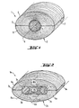
- FIG. 1 illustrates a molded complete shell element 1 which comprises a molded body of a single part 2 made of mineral fibers and a receiving opening 3 intended to receive a perforated exhaust pipe which, in this example, is coated with a layer 4 having the form of a flexible sheath of metallic wool, in particular of special steel wool.
- the molded body 2 made of mineral fibers is formed by two layers of mineral fibers 5 and 6 which touch at a contact surface or interface 7 on both sides of the receiving opening 3.
- the main orientation of the interface 7 is in this case radial with respect to the central axis 8 of the receiving opening 3.
- the flexible sheath intended to form the layer 4 of special steel wool and then compress the mandrel thus wrapped with the two layers 5 and 6 of mineral fibers in the mold.
- the layers of still raw mineral fibers 5 and 6 can then be arranged, in approximately the manner illustrated in FIG. 1, in the arched state, in corresponding halves of the mold so that, when the mold is closed, only the desired thickness reduction ⁇ in order to increase the density is in substance produced, the contact surfaces of the layers of mineral fibers 5 and 6 then being pressed against each other at the interface 7, catching on to each other with a densification effect and sticking to one another when the binder hardens.
- the molded body 2 of the molded element 1 is in one piece or surrounded by a complete shell but with because of its structure made of two separate layers of mineral fibers 5 and 6, it is a body in several pieces.
- a corresponding junction by hanging and gluing takes place in the known manner to layer 4 of special steel wool.
- FIG. 2 illustrates a molded element 1a which comprises two receiving openings 3a arranged one next to the other and at a certain distance from each other.
- the receiving openings 3a are not lined with a layer 4 of special steel wool or another material.
- the molded element 1a also comprises a single-piece molded body 2a which is formed, in several pieces, of layers of mineral fibers 5a and 6a on both sides of the receiving openings 3a as well as of an intermediate layer 9a of mineral fibers , in the area between the two receiving openings 3a.
- the interface 7a between the layers of mineral fibers 5a and 6a extends as in the embodiment shown in FIG.
- the manufacture of the molded element 1a can be carried out in a similar manner to that of the molded element 1, but two naked mandrels are arranged in the mold at the locations of the receptive openings 3a to be formed and between the mandrels is inserted intermediate layer 9a also still raw.
- the intermediate layer 9a is also densified correspondingly and then fills the space between the receiving openings 3a according to the desired density so that the material of the layers of mineral fibers 5a and 6a must simply fill the area surrounding the two receiving openings 3a.
- the intercalation of the intermediate layer 9a therefore makes it possible to prevent the material of the layers of mineral fibers 5a and 6a from having to be forced back into the zone situated between the receptor openings 3a and that consequently, if a sufficient density had to be obtained homogeneous, an increased initial thickness must be provided at this point.
- FIGS. 3 and 4 illustrate for example a molding operation intended to produce a molded element 1 which again comprises a molded body of a single part 2b formed, in several pieces, of the two layers of mineral fibers 5b and 6b.
- the mold comprises halves 12 and 13 which together form a molding cavity 14 corresponding to the external contour of the molded element 1b to be manufactured.
- a multiple mold is used, the halves 13 and 14 of which form several molding cavities 14 arranged one next to the other, may also have a considerable length which is a multiple of the length of the molded elements to be manufactured.
- long semi-finished products are molded in the molding cavities 14 which are placed one beside the other and which, by cutting, give the molded elements 1b.
- a single molding operation makes it possible to manufacture a large number of molded elements 1b.
- the layer of mineral fibers 5b is first placed on the lower half of the mold 12 in the present case and is then pushed back into the area of the molding cavity 14, which is indicated by the surface undulations 15 of the sheet of mineral fibers 5b. Then on the layer of mineral fibers 5b which is raw and not yet densified, a mandrel 17 is then placed, intended to form a receiving opening 3b at the desired location. It suffices in this case that the mandrel 17 is disposed without clamping at the approximate location of the receiving opening 3b to be produced.
- a second layer of mineral material 6b is placed on the mandrel 17 and on the layer of mineral fibers 5b and this layer 6b is also pushed back in a direction transverse to the axis of the mandrel 17, as indicated by surface undulations 16.
- a such permanent displacement of the layers of loose mineral fibers 5b and 6b, impregnated but not yet hardened can be carried out without problem and without the layers of mineral fibers 5b and 6b exerting a significant elastic recovery effect.
- a covering layer 18 made of glass fibers is disposed on the upper side of the mandrel 17 and extends approximately over half of the periphery of the mandrel.
- the mat-shaped covering layer 18 could in this example be made of fibers cut into borosilicate glass, aluminosilicate glass, quartz glass or rock wool which have a primary wire diameter of more than 10 ⁇ .Lm and of which a multiplicity or a large number of primary wires are connected by means of an organic sizing product or inorganic.
- the secondary wires thus formed divide completely or partially into their primary wires, the long elastic wires protecting the mineral fibers behind them by their extended surface; for this purpose, the molded element 1b is incorporated into the exhaust pipe in the inverted position relative to that illustrated in FIG. 4.
- the halves 12 and 13 of the mold are then brought from the position illustrated in FIG. 3 into that illustrated in FIG. 4, the mandrel 17 being attacked by suitable positioning means at the axial ends of the mold during closing and being suitably positioned.
- suitable positioning means are illustrated in dashed lines in FIGS. 3 and 4 and have the form of positioning stirrups 19 and 20 in V associated respectively with the lower half 12 and the upper half 13 of the mold, these stirrups attacking by their entry ramps the ends of the mandrel 17 and keeping them suitably in the final position shown in FIG. 4.
- Adequate discharge of the layers of mineral fibers 5b and 6b makes it possible without difficulty to ensure that, on both sides of the mandrel 17, there is an increased quantity of mineral fibrous material corresponding to the cross section of the molded element 1b to manufacture and also obtain here an essentially homogeneous density. Insofar as this can no longer be achieved sufficiently by, if need be, local pushing back of the fibrous mineral material, it is possible to work with additional layers of fibrous mineral material as clearly indicated in FIGS. 5 and 6.
- the molded element 1c illustrated in Figure 6 must be manufactured, this element. comprising a receiving opening 3c of relatively large diameter and having a relatively elongated outline which deviates greatly from a circular shape. Therefore, on both sides of the receiving opening 3c of the molded body 2c, a considerable amount of fibrous mineral material must be provided while on the upper and lower sides of the receiving opening 3c, as shown in the drawing, only a small thickness of the fibrous mineral material of the molded body 2c remains; in this reduced thickness, the fibrous mineral material must however be present in substance with the same density as on both sides of the receiving opening 3c.
- the molded body 2c is used to form layers of mineral fibers 5c and 6c which form the outer sides in the longitudinal direction of the molded body 2c and whose initial thickness is such that it ensures the desired densification of the mineral fibrous material on the upper face and on the lower face of the receiving opening 3c or of the mandrel 27 housed in this opening when the two mold halves indicated at 22 and 23 are brought into the closed position illustrated in FIG. 6.
- the quantity of mineral fibrous material present on both sides of the mandrel 27 coming from the layers of mineral fibers 5c and 6c is however much too small to produce in these places the desired densification.
- intermediate layers are placed in the form of strips 9c which provide in these places additional material.
- the width of the intermediate layers 9c which, for technical manufacturing reasons, are of rectangular section, may be such that the intermediate layers 9c, when they are applied to the mandrel 27, no longer quite reach the plane of lateral or junction separation 31 of the molding cavity 24, so that, thanks to the intermediate layers 9c, mineral fibrous material is supplied in the lateral zones immediately adjacent to the mandrel 27.
- the mandrel 27 can in this case be placed in a very simple manner on the layer of mineral fibers infé lower 5c. It is thus possible to guarantee a sufficiently uniform coating of the mandrel 27 by the material of the intermediate layers 9c by the fact that the mandrel 27 is raised by a suitable positioning device, for example a positioning stirrup as shown in the form of execution of FIGS. 3 and 4, during the movement of approximation of the halves 22 and 23 of the mold, so that the underside of the mandrel 27 is also easily accessible for the mineral fibrous material of the intermediate layers 9c.
- a suitable positioning device for example a positioning stirrup as shown in the form of execution of FIGS. 3 and 4
- the layers of mineral fibers 5c and 6c only touch at the level of the contact surfaces or interfaces 7c in the vicinity of the separation plane 31 while in the embodiment shown in FIGS. 3 and 4, the corresponding interface 7b of corrugated shape due to the discharge from the receiving opening 3b to the separation plane 21 is sufficient.
- the interface 7c is divided into interfaces 10c and 11c between the layer of mineral fibers 6c or the layer of mineral fibers 5c on the one hand and the intermediate layers 9c on the other hand .
- the receiving opening 3c of the molded element 1c could also be arranged if necessary in an eccentric position, in FIG. 6 slightly shifted to the right, without this causing any difficulty. so because the two intermediate layers 9c can simply be provided in different and corresponding widths.
- the mandrel 27 can of course be provided with a covering layer 18 or also with a layer 4 of special steel wool, when this proves desirable.
- the layers of individual mineral fibers such as layers 5c, 6c and 9c may have different initial densities or, in another way, different properties, for example different fiber lengths.
- the layers of mineral fibers of the examples chosen can be multiple, for example to obtain different properties in different areas of the molded element. It would thus be advantageous, for example to produce the layers of mineral fibers 5 and 6 of FIG. 1 in two parts, the internal layer containing long fibers and the external layer of short fibers, to take advantage, in the vicinity of the receiving opening.
- the conformation of a molded element in accordance with the respective requirements of the use case is only barely limited since the configuration can be prepared according to an initial distribution of the fibers. minerals to form the respective molded body which, after molding, gives a largely homogeneous density without defects.
- the receiving openings must also not be absolutely continuous in the longitudinal direction of each molded element, but they can also have the form of blind housings, in particular when considering incorporation in exhaust pipes which do not have of continuous exhaust pipe.
Landscapes
- Engineering & Computer Science (AREA)
- Chemical & Material Sciences (AREA)
- Combustion & Propulsion (AREA)
- Mechanical Engineering (AREA)
- General Engineering & Computer Science (AREA)
- Exhaust Silencers (AREA)
Claims (9)
Applications Claiming Priority (2)
| Application Number | Priority Date | Filing Date | Title |
|---|---|---|---|
| DE19833304809 DE3304809A1 (de) | 1983-02-11 | 1983-02-11 | Formteil aus mit bindemittel versehenen mineralfasern zur schalldaempfenden umkleidung eines perforierten abgasrohres, sowie verfahren zu seiner herstellung |
| DE3304809 | 1983-02-11 |
Publications (3)
| Publication Number | Publication Date |
|---|---|
| EP0128050A2 EP0128050A2 (de) | 1984-12-12 |
| EP0128050A3 EP0128050A3 (en) | 1986-04-02 |
| EP0128050B1 true EP0128050B1 (de) | 1988-08-17 |
Family
ID=6190649
Family Applications (1)
| Application Number | Title | Priority Date | Filing Date |
|---|---|---|---|
| EP84400270A Expired EP0128050B1 (de) | 1983-02-11 | 1984-02-09 | Formgepresster Teil aus mit einem Bindemittel versehenen Mineralfasern für schallisolierende Überdeckung eines perforierten Auspuffrohres sowie ein Verfahren seiner Herstellung |
Country Status (5)
| Country | Link |
|---|---|
| EP (1) | EP0128050B1 (de) |
| DE (2) | DE3304809A1 (de) |
| ES (1) | ES8500382A1 (de) |
| FI (1) | FI78970C (de) |
| PT (1) | PT78093B (de) |
Cited By (1)
| Publication number | Priority date | Publication date | Assignee | Title |
|---|---|---|---|---|
| US11746682B2 (en) | 2021-03-08 | 2023-09-05 | Nakagawa Sangyo Co., Ltd. | Method for manufacturing a vehicle muffler |
Families Citing this family (7)
| Publication number | Priority date | Publication date | Assignee | Title |
|---|---|---|---|---|
| DE3826707A1 (de) * | 1988-08-05 | 1990-02-08 | Gruenzweig & Hartmann | Verfahren zum herstellen eines abgas-schalldaempfers |
| GB9817973D0 (en) * | 1998-08-19 | 1998-10-14 | Lancaster Glass Fibre | Silencer Cartridge |
| US6196351B1 (en) | 1999-06-04 | 2001-03-06 | Lancaster Glass Fibre Limited | Silencer cartridge |
| JP2003041923A (ja) * | 2001-07-30 | 2003-02-13 | Honda Motor Co Ltd | 排気消音装置 |
| FR2883921B1 (fr) * | 2005-04-05 | 2010-06-11 | Faurecia Sys Echappement | Sourdine pour silencieux de ligne d'echappement |
| DE102007010814A1 (de) * | 2007-03-06 | 2008-09-11 | Arvinmeritor Emissions Technologies Gmbh | Schalldämpfer-Dämmelement, Schalldämpfer sowie Verfahren zur Herstellung eines Schalldämpfers |
| DE102014012866A1 (de) | 2014-04-09 | 2015-10-15 | Klaus Sommer | Schallabsorbierendes / - dämmendes System aus nicht brennbaren Naturstoffen |
Family Cites Families (9)
| Publication number | Priority date | Publication date | Assignee | Title |
|---|---|---|---|---|
| DE7223051U (de) * | 1973-04-12 | Deutsches Metallfaserwerk Bullmer Und Schwabbauer | Vliesstoffbahn aus hitze- und korrosionsbeständigem Werkstoff als schallschluckende Füllung für Schalldämpfer bei Verbrennungskraftmaschinen | |
| DE7628169U1 (de) * | 1976-09-09 | 1976-12-30 | Gruenzweig + Hartmann Und Glasfaser Ag, 6700 Ludwigshafen | Mineralfaser-konfektionsteil |
| JPS5428952A (en) * | 1977-08-09 | 1979-03-03 | Toyota Motor Corp | Silencer for internal combustion engine |
| DE7732170U1 (de) * | 1977-10-18 | 1982-09-30 | Grünzweig + Hartmann und Glasfaser AG, 6700 Ludwigshafen | Formteil zur auskleidung von schalldaempfern an auspuffrohren |
| DE2760151C2 (de) * | 1977-10-18 | 1987-05-14 | Grünzweig + Hartmann und Glasfaser AG, 6700 Ludwigshafen | Formteil zur Auskleidung von Schalldämpfern an Abgasrohren |
| DE8204025U1 (de) * | 1982-02-13 | 1982-07-22 | Seitz, Wilfried, 6238 Hofheim | Schalldaempf-fuellung fuer einen auspufftopf |
| DE3205185C2 (de) * | 1982-02-13 | 1985-12-12 | Wilfried 6238 Hofheim Seitz | Verfahren zum Herstellen einer Schalldämpf-Füllung für einen Auspufftopf sowie nach diesem Verfahren hergestellte Schalldämpf-Füllung |
| DE3205186A1 (de) * | 1982-02-13 | 1983-08-25 | Wilfried 6238 Hofheim Seitz | Verfahren zum herstellen einer schalldaempf-fuellung fuer einen auspufftopf |
| GB2120318B (en) * | 1982-05-13 | 1985-07-17 | Ti Cheswick Silencers Limited | Exhaust gas discharge system |
-
1983
- 1983-02-11 DE DE19833304809 patent/DE3304809A1/de not_active Withdrawn
-
1984
- 1984-02-09 ES ES529587A patent/ES8500382A1/es not_active Expired
- 1984-02-09 EP EP84400270A patent/EP0128050B1/de not_active Expired
- 1984-02-09 DE DE8484400270T patent/DE3473491D1/de not_active Expired
- 1984-02-10 PT PT78093A patent/PT78093B/de not_active IP Right Cessation
- 1984-02-10 FI FI840549A patent/FI78970C/fi not_active IP Right Cessation
Cited By (1)
| Publication number | Priority date | Publication date | Assignee | Title |
|---|---|---|---|---|
| US11746682B2 (en) | 2021-03-08 | 2023-09-05 | Nakagawa Sangyo Co., Ltd. | Method for manufacturing a vehicle muffler |
Also Published As
| Publication number | Publication date |
|---|---|
| FI78970C (fi) | 1989-10-10 |
| FI840549A7 (fi) | 1984-08-12 |
| FI78970B (fi) | 1989-06-30 |
| DE3473491D1 (en) | 1988-09-22 |
| EP0128050A3 (en) | 1986-04-02 |
| ES529587A0 (es) | 1984-11-01 |
| FI840549A0 (fi) | 1984-02-10 |
| PT78093A (de) | 1984-03-01 |
| ES8500382A1 (es) | 1984-11-01 |
| PT78093B (de) | 1986-03-27 |
| EP0128050A2 (de) | 1984-12-12 |
| DE3304809A1 (de) | 1984-08-16 |
Similar Documents
| Publication | Publication Date | Title |
|---|---|---|
| EP1239454B1 (de) | Herstellungsverfahren einer Platte mit angepasster, schallwiederstandsfähiger Schicht, sowie die hergestellte Platte | |
| EP1213703B1 (de) | Akustische Platte mit Sandwichaufbau | |
| EP2245205B1 (de) | Verfahren zur herstellung eines keramikfaserverstärkten metallteils | |
| EP2245204B1 (de) | Verfahren zur herstellung von teilen mit einem einsatz aus einem metallmatrixverbundmaterial | |
| EP0128050B1 (de) | Formgepresster Teil aus mit einem Bindemittel versehenen Mineralfasern für schallisolierende Überdeckung eines perforierten Auspuffrohres sowie ein Verfahren seiner Herstellung | |
| EP1157372B1 (de) | Verfahren zur herstellung einer schalldämmenden platte mit widerstandschicht mit struktureigenschaften und zugehöriger platte. | |
| EP3916717B1 (de) | Schalldämmende wabenstruktur mit einer membran, die mit einem rohr versehen ist, das für die verarbeitung verschiedener akustischer frequenzen konfiguriert ist, verfahren zur herstellung einer solchen schalldämmenden wabenstruktur und entsprechendes werkzeug | |
| EP2191029B1 (de) | Mechanisches teil mit einem einschub aus einem verbundwerkstoff | |
| FR2569237A1 (fr) | Dispositif de protection thermique resistant a l'ablation et aux vibrations, et un procede de fabrication | |
| FR2918134A1 (fr) | Bielle structurale en materiau composite et procede de realisation d'une bielle en materiau composite | |
| FR2929168A1 (fr) | Panneau composite a ame perforee, dispositif et procede pour fabriquer un tel panneau | |
| CA2729377A1 (fr) | Procede de fabrication d'une piece metallique renforcee de fibres ceramiques | |
| WO1984000186A1 (fr) | Fibres de renforcement de materiaux moulables a liant hydraulique ou non et leur fabrication | |
| EP3043347B1 (de) | Schalldämmendes Verkleidungspaneel, und Luftfahrzeug | |
| WO2013017796A1 (fr) | Dispositif pour l'aide a la découpe d'une couche de texture fibreuse enroulée sur un mandrin d'imprégnation d'une machine d'enroulement | |
| EP0081834B1 (de) | Leichtgebauter Ski mit Kern und sein Herstellungsverfahren | |
| WO2015082843A1 (fr) | Panneau sandwich comprenant une structure en nid d'abeille disposant de renforts sur les bords de cette structure | |
| CA2783421A1 (fr) | Procede de fabrication d'un insert de forme droite en materiau composite a matrice metallique | |
| EP1322807B1 (de) | Verfahren und vorrichtung zur herstellung von mineralfaserfilzen | |
| FR3113170A1 (fr) | Matériau acoustique en bande à bride intégrée, et paroi interne d’une entrée d’air d’aéronef réalisée avec ce matériau | |
| EP3981481B1 (de) | Strukturelement eines gleitbretts und herstellungsverfahren | |
| EP2552629B1 (de) | Verfahren zur herstellung eines verlängerten einsatzes aus einem metallmatrixverbundstoff | |
| FR2820712A1 (fr) | Noyau surf a tubes | |
| FR2655976A1 (fr) | Procede pour la realisation de structure composite, bande d'agrafes en materiau composite permettant la mise en óoeuvre du procede et procede de fabrication de la bande d'agrafes. | |
| FR2820713A1 (fr) | Noyau surf a evidements debouchants |
Legal Events
| Date | Code | Title | Description |
|---|---|---|---|
| PUAI | Public reference made under article 153(3) epc to a published international application that has entered the european phase |
Free format text: ORIGINAL CODE: 0009012 |
|
| AK | Designated contracting states |
Designated state(s): BE DE FR GB IT NL SE |
|
| PUAL | Search report despatched |
Free format text: ORIGINAL CODE: 0009013 |
|
| AK | Designated contracting states |
Kind code of ref document: A3 Designated state(s): BE DE FR GB IT NL SE |
|
| 17P | Request for examination filed |
Effective date: 19860806 |
|
| 17Q | First examination report despatched |
Effective date: 19870715 |
|
| GRAA | (expected) grant |
Free format text: ORIGINAL CODE: 0009210 |
|
| AK | Designated contracting states |
Kind code of ref document: B1 Designated state(s): BE DE FR GB IT NL SE |
|
| REF | Corresponds to: |
Ref document number: 3473491 Country of ref document: DE Date of ref document: 19880922 |
|
| ITF | It: translation for a ep patent filed | ||
| GBT | Gb: translation of ep patent filed (gb section 77(6)(a)/1977) | ||
| PLBE | No opposition filed within time limit |
Free format text: ORIGINAL CODE: 0009261 |
|
| STAA | Information on the status of an ep patent application or granted ep patent |
Free format text: STATUS: NO OPPOSITION FILED WITHIN TIME LIMIT |
|
| 26N | No opposition filed | ||
| ITTA | It: last paid annual fee | ||
| PGFP | Annual fee paid to national office [announced via postgrant information from national office to epo] |
Ref country code: SE Payment date: 19930902 Year of fee payment: 11 |
|
| PGFP | Annual fee paid to national office [announced via postgrant information from national office to epo] |
Ref country code: GB Payment date: 19940118 Year of fee payment: 11 |
|
| PGFP | Annual fee paid to national office [announced via postgrant information from national office to epo] |
Ref country code: FR Payment date: 19940121 Year of fee payment: 11 |
|
| PGFP | Annual fee paid to national office [announced via postgrant information from national office to epo] |
Ref country code: BE Payment date: 19940127 Year of fee payment: 11 |
|
| PGFP | Annual fee paid to national office [announced via postgrant information from national office to epo] |
Ref country code: NL Payment date: 19940228 Year of fee payment: 11 |
|
| EAL | Se: european patent in force in sweden |
Ref document number: 84400270.9 |
|
| PG25 | Lapsed in a contracting state [announced via postgrant information from national office to epo] |
Ref country code: GB Effective date: 19950209 |
|
| PG25 | Lapsed in a contracting state [announced via postgrant information from national office to epo] |
Ref country code: SE Effective date: 19950210 |
|
| PG25 | Lapsed in a contracting state [announced via postgrant information from national office to epo] |
Ref country code: BE Effective date: 19950228 |
|
| BERE | Be: lapsed |
Owner name: ISOVER SAINT-GOBAIN Effective date: 19950228 |
|
| PG25 | Lapsed in a contracting state [announced via postgrant information from national office to epo] |
Ref country code: NL Effective date: 19950901 |
|
| GBPC | Gb: european patent ceased through non-payment of renewal fee |
Effective date: 19950209 |
|
| PG25 | Lapsed in a contracting state [announced via postgrant information from national office to epo] |
Ref country code: FR Effective date: 19951031 |
|
| NLV4 | Nl: lapsed or anulled due to non-payment of the annual fee |
Effective date: 19950901 |
|
| EUG | Se: european patent has lapsed |
Ref document number: 84400270.9 |
|
| REG | Reference to a national code |
Ref country code: FR Ref legal event code: ST |
|
| PGFP | Annual fee paid to national office [announced via postgrant information from national office to epo] |
Ref country code: DE Payment date: 19980307 Year of fee payment: 15 |
|
| PG25 | Lapsed in a contracting state [announced via postgrant information from national office to epo] |
Ref country code: DE Free format text: LAPSE BECAUSE OF NON-PAYMENT OF DUE FEES Effective date: 19991201 |