EP0081834B1 - Leichtgebauter Ski mit Kern und sein Herstellungsverfahren - Google Patents
Leichtgebauter Ski mit Kern und sein Herstellungsverfahren Download PDFInfo
- Publication number
- EP0081834B1 EP0081834B1 EP19820111526 EP82111526A EP0081834B1 EP 0081834 B1 EP0081834 B1 EP 0081834B1 EP 19820111526 EP19820111526 EP 19820111526 EP 82111526 A EP82111526 A EP 82111526A EP 0081834 B1 EP0081834 B1 EP 0081834B1
- Authority
- EP
- European Patent Office
- Prior art keywords
- ski
- tube
- core
- fact
- tubes
- Prior art date
- Legal status (The legal status is an assumption and is not a legal conclusion. Google has not performed a legal analysis and makes no representation as to the accuracy of the status listed.)
- Expired
Links
- 238000000034 method Methods 0.000 title claims description 13
- 229920003002 synthetic resin Polymers 0.000 claims description 14
- 239000000057 synthetic resin Substances 0.000 claims description 14
- 229920002994 synthetic fiber Polymers 0.000 claims description 12
- 230000001413 cellular effect Effects 0.000 claims description 9
- 239000000956 alloy Substances 0.000 claims description 7
- 229910045601 alloy Inorganic materials 0.000 claims description 7
- 238000002347 injection Methods 0.000 claims description 7
- 239000007924 injection Substances 0.000 claims description 7
- 229920005989 resin Polymers 0.000 claims description 6
- 239000011347 resin Substances 0.000 claims description 6
- 238000000465 moulding Methods 0.000 claims description 3
- 239000004417 polycarbonate Substances 0.000 claims description 3
- 229920000515 polycarbonate Polymers 0.000 claims description 3
- 229920005992 thermoplastic resin Polymers 0.000 claims description 3
- 229920001187 thermosetting polymer Polymers 0.000 claims description 3
- 229920001971 elastomer Polymers 0.000 claims description 2
- 239000000806 elastomer Substances 0.000 claims description 2
- 238000004519 manufacturing process Methods 0.000 description 9
- 239000000463 material Substances 0.000 description 9
- 239000002184 metal Substances 0.000 description 8
- 230000027455 binding Effects 0.000 description 4
- 238000009739 binding Methods 0.000 description 4
- 229920003023 plastic Polymers 0.000 description 4
- 239000004033 plastic Substances 0.000 description 4
- 229920005830 Polyurethane Foam Polymers 0.000 description 3
- XECAHXYUAAWDEL-UHFFFAOYSA-N acrylonitrile butadiene styrene Chemical compound C=CC=C.C=CC#N.C=CC1=CC=CC=C1 XECAHXYUAAWDEL-UHFFFAOYSA-N 0.000 description 3
- 229920000122 acrylonitrile butadiene styrene Polymers 0.000 description 3
- 239000004676 acrylonitrile butadiene styrene Substances 0.000 description 3
- 239000003365 glass fiber Substances 0.000 description 3
- 239000011796 hollow space material Substances 0.000 description 3
- 239000011496 polyurethane foam Substances 0.000 description 3
- 230000002787 reinforcement Effects 0.000 description 3
- 230000003014 reinforcing effect Effects 0.000 description 3
- 238000004873 anchoring Methods 0.000 description 2
- 239000004744 fabric Substances 0.000 description 2
- 238000010438 heat treatment Methods 0.000 description 2
- 239000004922 lacquer Substances 0.000 description 2
- 230000036961 partial effect Effects 0.000 description 2
- 230000000149 penetrating effect Effects 0.000 description 2
- 229920002635 polyurethane Polymers 0.000 description 2
- 239000004814 polyurethane Substances 0.000 description 2
- 230000001681 protective effect Effects 0.000 description 2
- 239000007787 solid Substances 0.000 description 2
- 239000002966 varnish Substances 0.000 description 2
- OKTJSMMVPCPJKN-UHFFFAOYSA-N Carbon Chemical compound [C] OKTJSMMVPCPJKN-UHFFFAOYSA-N 0.000 description 1
- VVQNEPGJFQJSBK-UHFFFAOYSA-N Methyl methacrylate Chemical compound COC(=O)C(C)=C VVQNEPGJFQJSBK-UHFFFAOYSA-N 0.000 description 1
- 229920005372 Plexiglas® Polymers 0.000 description 1
- 239000004760 aramid Substances 0.000 description 1
- 229920003235 aromatic polyamide Polymers 0.000 description 1
- 230000015572 biosynthetic process Effects 0.000 description 1
- 229910052799 carbon Inorganic materials 0.000 description 1
- 239000000470 constituent Substances 0.000 description 1
- 238000010276 construction Methods 0.000 description 1
- 230000007423 decrease Effects 0.000 description 1
- 230000003247 decreasing effect Effects 0.000 description 1
- 239000006260 foam Substances 0.000 description 1
- 230000000670 limiting effect Effects 0.000 description 1
- 230000005226 mechanical processes and functions Effects 0.000 description 1
- 238000003825 pressing Methods 0.000 description 1
- 230000002829 reductive effect Effects 0.000 description 1
- 230000004584 weight gain Effects 0.000 description 1
- 235000019786 weight gain Nutrition 0.000 description 1
- 238000004804 winding Methods 0.000 description 1
Images


Classifications
-
- A—HUMAN NECESSITIES
- A63—SPORTS; GAMES; AMUSEMENTS
- A63C—SKATES; SKIS; ROLLER SKATES; DESIGN OR LAYOUT OF COURTS, RINKS OR THE LIKE
- A63C5/00—Skis or snowboards
- A63C5/12—Making thereof; Selection of particular materials
- A63C5/126—Structure of the core
-
- A—HUMAN NECESSITIES
- A63—SPORTS; GAMES; AMUSEMENTS
- A63C—SKATES; SKIS; ROLLER SKATES; DESIGN OR LAYOUT OF COURTS, RINKS OR THE LIKE
- A63C5/00—Skis or snowboards
- A63C5/12—Making thereof; Selection of particular materials
Definitions
- the present invention relates generally to the field of skis and their manufacturing process.
- skis having a hollow tubular structure by placing inside a mold tubes made of glass fiber fabric impregnated with a thermosetting material, formed around air chambers which are inflated up to the strands conform to the shape of the mold (see FR-A-1 303 210).
- this process appears to be relatively complicated and expensive and is not very suitable for the manufacture of skis of the core type made of expanded cellular material.
- the aim of the present invention is to produce a lighter ski while retaining the advantages which the production of skis of the core type made of expanded cellular material obtained by injection or molding, and in particular skis of the polyurethane foam core type and while retaining and even improving the mechanical characteristics of current skis.
- the present invention therefore relates first of all to a method for producing, in a mold, a ski core of injected or molded cellular synthetic material, in which this synthetic material is expanded around a hollow tubular structure formed by at least one tube. extending longitudinally. It also relates to the nucleus obtained by this process.
- the ends of said tube are closed before the injection or molding operation so that the cellular synthetic material cannot, during its expansion, penetrate inside said tube.
- the method according to the present invention can also have different variants. Indeed, at least one of the ends of said tube can be closed prior to its introduction into the mold.
- said tube can advantageously adapt to the shapes and to the arrangement of the other elements arranged in the mold such as the inserts for the anchoring of shoe fixing screws and can advantageously follow the profile of the ski, without this tube has previously been completely compliant with this profile.
- the present invention also relates to a ski which can advantageously be manufactured using the above method.
- the ski according to the present invention comprises an elongated body and in the extension of this body a heel and a spatula and is of the core type made of a cellular synthetic material, injected or molded, this core comprising a tubular structure delimiting therein a longitudinal hollow space.
- This core is surrounded, as is known, by resistant or decorative outer layers to form the final ski.
- said tubular structure is formed by at least one rigid or semi-rigid synthetic resin tube, the ends of said tube being closed and said tube extending, in the core, longitudinally over at least part of said body.
- At least one end of said tube is closed by a plug.
- At least one of the ends or end portions of said tube are at least partially flattened, flattened or oval and have, in the direction of the thickness of the ski, a thickness equal to or less than l 'core thickness.
- At least one end of said tube can be completely flattened or flattened.
- said tube can be in the shape of the cone converging towards one end of the ski.
- said tube may extend between the heel and the tip of the ski and have a part in the form of a converging cone extending from the middle part of the ski towards the tip and a part in the form of a converging cone extending from the middle part of the ski towards the heel.
- said tube may comprise, preferably in the middle part of the ski, a part in the shape of a cylinder.
- these parts can be mounted or assembled by means of a sleeve.
- the synthetic resin forming said tube can be any. It suffices in fact that it is rigid or semi-rigid and that it has sufficient thermal stability. health so that during its formation it does not break, in order to prevent the cellular synthetic material from penetrating inside this tube and so that it does not crush completely under the pressure exerted by the synthetic material cell during its expansion.
- thermoplastic resin a thermoplastic resin
- thermosetting resin a thermosetting resin
- elastomer a thermoplastic resin
- alloy of synthetic resins and in particular an alloy of thermoplastic resins.
- the resin alloy it is preferable to choose an ABS alloy (acrylonitrile-butadiene-styrene resin) and a polycarbonate.
- the tube placed in the core can have a certain mechanical function and constitute a reinforcing structure while allowing lightening of this core.
- said tubular structure can obviously be formed of several tubes.
- one can provide a tubular structure comprising two tubes arranged symmetrically with respect to the longitudinal axis of the ski.
- One can also provide a tube arranged along the longitudinal axis of the ski.
- the manufacturing process and the particular choice of a tube made of a rigid or semi-rigid synthetic material have many advantages.
- the choice of a plastic tube closed at its ends and the fact of creating a hollow space makes it possible to obtain a significantly lightened core compared to a solid core.
- the hollow structure according to the present invention makes it possible to considerably reduce the volume of the core and in particular its thickness, which is an advantage when the core is formed by a polyurethane foam which is relatively heavy. It also makes it possible to reduce the thicknesses of the mechanical structure associated with the core and can, in certain cases, allow its removal. Consequently, the reinforcing structure according to the present invention allows weight gain on the ski.
- the plastic tube and the surrounding cellular material cooperate, by self-bonding in contact with the foam during its expansion so as to form a mechanical unit.
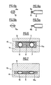
- the ski 1 comprises a body 2 which is extended at one of its ends by a heel 3 and at the other of its ends by a tip 4.
- the ski 1 comprises, in its body 2, a tubular structure generally identified by the reference 5.
- the tubular structure 5 is formed, in the example shown, by two longitudinal tubes 6 and 7 which are arranged symmetrically with respect to to the longitudinal axis of the ski 1. In the example shown, these tubes have the same length and extend in the body 2 of the latter without however reaching its ends.
- the tubes 6 and 7 are identical and are hollow. They are also formed from a cylindrical tube made of semi-rigid synthetic resin.
- the ski 1 comprises a core 8 made of an expanded cellular synthetic resin, for example made of polyurethane foam, produced by injection and expansion in a mold.
- the core 8 is covered by an upper carrier layer 9 and by a lower carrier layer 10.
- These carrier layers 9 and 10 can simply cover the upper and lower faces of the core 8 so as to form a sandwich type ski or may form an integral part of a box completely surrounding the core 8.
- a metal or synthetic plate 11 intended for the anchoring of the screws of the bindings.
- the tubes 6 and 7, and in particular the tube 6, have their front end 6a and 7a and their rear end 6b and 7b closed as will be seen below with reference to Figures 5a and 5b.
- the tubes 6 and 7 are, in the middle part of the ski, substantially cylindrical and have a diameter substantially equal to the distance separating the insert 11 and the lower layer 10.
- the tube 6 has a front end portion 6c which is progressively ovalized to substantially follow the profile of the core 8, and consequently the profile of the ski 1. In this portion, the tube 6 has an oval section decreasing towards the end 6a.
- the tube 6 also has a progressively crushed rear end portion following the profile of the core 8 and has in this portion an oval section which decreases. We will explain later how these ovalized portions can be obtained simply.
- the tube 7 is shaped in the same way as the tube 6.
- the end 6a of the tube 6 is crushed so as to take an oval shape and a stopper 12 having the same shape is placed inside this end 6a so as to close off the tube 6.
- the end 6a of the tube 6 is completely flattened and is fixed in this state. It can be fixed there, for example by self-bonding by heating this end. In this case, no plug is necessary.
- the variant of the ski structure shown in FIG. 3 is not limiting.
- the tubes 6 and 7 can extend over any length of the body 2 of the ski 1. A condition is however preferably to be observed. Indeed, it is preferable that the thickness of the ends of the tubes is less than or equal to the thickness of the core at the right of these ends.
- the tubes 6 and 7 extend in the middle part of the core 8 so that at least one of their ends is located at a place in this core where its thickness is greater than or equal to the outside diameter of the tubes 6 and 7, these ends can simply be plugged with a plug of circular section, this plug penetrating inside the tube. If, however, a plug is provided which surrounds this end of the tube, the outside diameter of this plug must be less than the thickness of the core 8 at the place where this plug is located in the core 8.
- the mold 13 is closed by placing its upper part 15 on its lower part 14, the parts 14 and 15 defining a hollow space having the shape of the desired core.
- this mold 13 is closed, the end portions of the tubes 6 and 7 are crushed, by being ovalized, between the lower part 14 and the upper part 15 of the mold and according to the profile of the mold, as can be seen. see in figure 7.
- the synthetic resin is injected such as polyurethane which expands in the mold 13 but which does not penetrate inside the tubes 6 and 7 since their ends are closed.
- the synthetic resin is expanded, the tubes leave two longitudinal hollow spaces in the core.
- the ski manufacturing process is continued to obtain, for example, a ski of the type that will be described with reference to FIGS. 11 and 12.
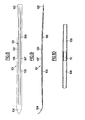
- the ski 101 comprises a body 102 which is extended at one of its ends by a heel 103 and at the other of its ends by a spatula 104.
- the ski 101 comprises, in its body 102, a reinforcement structure generally identified by the reference 105.
- the reinforcement structure 105 is formed by two longitudinal tubes 106 and 107 arranged symmetrically with respect to the longitudinal axis 101, these tubes 106 and 107 extending in the body 102, from the heel 103 to the tip 104.
- the tubes 106 and 107 are formed in the same way.
- the tube 107 comprises, for manufacturing reasons, a part 108 in the form of a converging cone extending from the middle part of the ski 101 to the tip 104 and a part 109 in the form of a cone extending from the part median of the ski 101 towards the heel 103, the generatrices of said cones being substantially straight.
- the parts 108 and 109 of the tube 107 are arranged end to end and are connected by a sleeve 110 which, in the example shown, penetrates inside the ends of the parts 108 and 109 .
- the ends of the tubes 106 and 107 are substantially point-shaped and are closed so that the tubes 106 and 107 are hollow and inaccessible from the outside.
- the tubes 106 and 107 are, in the figures, of circular section and are substantially centered in the thickness direction of the ski. We see that they follow approximately the profile of the ski.
- the tubes 106 and 107 may however have a different section. They may for example be of oval section but will preferably have their ends in the shape of a point or in the form of a blade of small width.
- junction between the parts 108 and 109 of the tube 107 as the junction between the corresponding parts of the tube 106 will preferably be disposed in the middle part of the ski where the binding of the boot is attached.
- FIGS. 11 and 12 show sections of skis having particular structures and in which are incorporated conical tubes similar to the tubes 106 and 107 provided in FIGS. 8 and 9.
- FIG. 11 shows a ski generally identified by the reference 111 which is of the sandwich type.
- the ski 111 comprises an upper plate 112 provided on its upper face with a varnish or a protective lacquer 113, a lower plate 114 provided on its lower face with a sole 115 and metal edges 116 and 117. Between the upper plate 112 and the lower plate 114 is, sandwiched, the core 118.
- the core 118 Inside the core 118 are embedded two tubes 119 and 120 which are arranged symmetrically with respect to the longitudinal axis of the ski and which extend, in the central part of the ski, between the metal plate 121 provided for mounting the shoe binding and the bottom plate 114.
- the core 118 completely surrounds the tubes 119 and 120 which are of circular and hollow section.
- Figure 12 shows the section of a ski generally identified by the reference 122 which is of the box type.
- the ski 122 in fact comprises a torsion box 123 comprising inside a core 124, a sole 125 on the underside of the torsion box 123, two metal edges 126 and 127, two upper edges 128 and 129, plates field 130 and 131 mounted against the lateral faces of the torsion box 123 between the edges 126, 128 and 127, 129 and a protective varnish or lacquer 132 which extends on the upper face of the torsion box 123 and on the upper edges 128 and 129.
- the skis shown in FIGS. 11 and 12 are constructed using plastic or synthetic materials as is well known today.
- the core 118 of the ski 11 and the core 124 of the ski 122 can be formed by an expanded polyurethane or plexiglass.
- the tubes 119, 120 and 133, 134 are preferably formed by a laminate comprising a fabric of glass fibers embedded in a resin.
- the tubes 119, 120 and 133, 134 can be manufactured according to known methods and in particular by winding.
- the skis shown in FIGS. 11 and 12 can be manufactured according to known methods, the tubes 119, 120 and 133, 134 being prefabricated and suitably placed inside the space which must subsequently form the cores 118 and 124 which are in general made by injection. As the tubes are completely closed, the injected material intended to form the core of the ski will not penetrate into the tubes.
- the present invention is not limited to the examples described above. Provision may in fact be made for incorporating into the core of the ski tubes of different shape having different lengths and distributed in a different manner inside the core. It is also possible to incorporate tubes into the core of skis having structures different from those shown in FIGS. 11 and 12 and in particular tubes could be incorporated into skis having an internal omega structure. In this case, it could advantageously be provided to have a tube on either side of the omega and a tube inside the core of the omega.
Landscapes
- Injection Moulding Of Plastics Or The Like (AREA)
- Rigid Pipes And Flexible Pipes (AREA)
- Laminated Bodies (AREA)
Claims (14)
Priority Applications (1)
| Application Number | Priority Date | Filing Date | Title |
|---|---|---|---|
| AT82111526T ATE16460T1 (de) | 1981-12-15 | 1982-12-13 | Leichtgebauter ski mit kern und sein herstellungsverfahren. |
Applications Claiming Priority (4)
| Application Number | Priority Date | Filing Date | Title |
|---|---|---|---|
| FR8123366 | 1981-12-15 | ||
| FR8123366A FR2517978A1 (fr) | 1981-12-15 | 1981-12-15 | Ski du type a noyau a structure allegee et son procede de fabrication |
| FR8123365A FR2517977A1 (fr) | 1981-12-15 | 1981-12-15 | Perfectionnements aux skis notamment du type a noyau en resine synthetique cellulaire |
| FR8123365 | 1981-12-15 |
Publications (2)
| Publication Number | Publication Date |
|---|---|
| EP0081834A1 EP0081834A1 (de) | 1983-06-22 |
| EP0081834B1 true EP0081834B1 (de) | 1985-11-13 |
Family
ID=26222667
Family Applications (1)
| Application Number | Title | Priority Date | Filing Date |
|---|---|---|---|
| EP19820111526 Expired EP0081834B1 (de) | 1981-12-15 | 1982-12-13 | Leichtgebauter Ski mit Kern und sein Herstellungsverfahren |
Country Status (2)
| Country | Link |
|---|---|
| EP (1) | EP0081834B1 (de) |
| DE (2) | DE81834T1 (de) |
Cited By (1)
| Publication number | Priority date | Publication date | Assignee | Title |
|---|---|---|---|---|
| WO2001045811A1 (de) | 1999-12-22 | 2001-06-28 | Atomic Austria Gmbh | Brettartiges gleitgerät, insbesondere schi oder snowboard |
Families Citing this family (8)
| Publication number | Priority date | Publication date | Assignee | Title |
|---|---|---|---|---|
| FR2658090B1 (fr) * | 1990-02-15 | 1992-04-30 | Salomon Sa | Procede d'assemblage d'un ski par surmoulage, et structure de ski obtenue par ce procede. |
| US5848800A (en) * | 1993-06-09 | 1998-12-15 | Kastle Aktiengesellschaft | Ski |
| DE4325091A1 (de) * | 1993-07-27 | 1995-02-02 | Uwe Emig | Aus mehreren Elementen zusammengesetzter Ski |
| FR2715316B1 (fr) * | 1994-01-25 | 1996-03-15 | Rossignol Sa | Procédé de fabrication d'un ski. |
| FR2715317B1 (fr) * | 1994-01-25 | 1996-03-01 | Rossignol Sa | Ski et procédé de fabrication. |
| US5759664A (en) * | 1996-02-29 | 1998-06-02 | Goode Ski Technologies | Composite ski |
| AT500325A1 (de) * | 2002-11-06 | 2005-12-15 | Tyrolia Technology Gmbh | Gleitbrett, insbesondere ski |
| FR2851475B1 (fr) | 2003-02-26 | 2006-10-13 | Salomon Sa | Paire de skis prevus pour la pratique de la glisse et notamment du ski alpin |
Family Cites Families (5)
| Publication number | Priority date | Publication date | Assignee | Title |
|---|---|---|---|---|
| FR1276744A (fr) * | 1960-10-12 | 1961-11-24 | Ski | |
| FR1303210A (fr) * | 1961-05-03 | 1962-09-07 | Haldemann S A | Procédé de fabrication d'un objet creux alvéolé et objet tel que ski obtenu par ce procédé |
| US3493240A (en) * | 1967-06-06 | 1970-02-03 | Herbert R Jenks | Laminated fiber glass ski and process for making the same |
| DE2124061A1 (de) * | 1971-05-14 | 1972-11-23 | Farbwerke Hoechst AG, vormals Meister Lucius & Brüning, 6000 Frankfurt | Ski-Grundkörper aus Kunststoff |
| FR2345176A1 (fr) * | 1976-03-22 | 1977-10-21 | Bondivenne Jules | Perfectionnement a la construction des skis en utilisant une structure creuse metallique |
-
1982
- 1982-12-13 EP EP19820111526 patent/EP0081834B1/de not_active Expired
- 1982-12-13 DE DE1982111526 patent/DE81834T1/de active Pending
- 1982-12-13 DE DE8282111526T patent/DE3267463D1/de not_active Expired
Cited By (1)
| Publication number | Priority date | Publication date | Assignee | Title |
|---|---|---|---|---|
| WO2001045811A1 (de) | 1999-12-22 | 2001-06-28 | Atomic Austria Gmbh | Brettartiges gleitgerät, insbesondere schi oder snowboard |
Also Published As
| Publication number | Publication date |
|---|---|
| DE81834T1 (de) | 1983-12-08 |
| DE3267463D1 (en) | 1985-12-19 |
| EP0081834A1 (de) | 1983-06-22 |
Similar Documents
| Publication | Publication Date | Title |
|---|---|---|
| EP0428885B1 (de) | Verfahren zur Herstellung eines Skis durch Injektion, und Skistruktur | |
| EP0230839B1 (de) | Fahrradgabel oder gleichartiger Artikel aus mit Textilstruktur verstärktem Kunstharz als Hauptbestandteil und Verfahren zu seiner Herstellung | |
| WO1997033666A1 (fr) | Chassis renforce pour patin a roulettes | |
| FR2620628A2 (fr) | Procede pour realiser un ski et ski fait selon ce procede | |
| EP0081834B1 (de) | Leichtgebauter Ski mit Kern und sein Herstellungsverfahren | |
| EP1015301B1 (de) | Fahrradgabel | |
| EP2008835A1 (de) | Rad mit ausbaubarer Speiche aus Verbundmaterial | |
| EP1683552A1 (de) | Tischtennis-Schläger | |
| EP0498963B1 (de) | Ski zum Gleiten auf Schnee und Eis | |
| EP3225288B1 (de) | Schläger, insbesondere struktur eines padel-schlägers | |
| EP0650747A1 (de) | Verfahren zum Herstellen eines Skis in einer Form | |
| FR2720713A1 (fr) | Cadre de bicyclette en matériau composite, moules pour la réalisation d'un tel cadre, et procédé de moulage du cadre. | |
| EP0203857B1 (de) | Mast, insbesondere zum Tragen von elektrischen oder telefonischen Leitungen | |
| EP0665034A1 (de) | Ski mit "in situ" injiziertem Kern | |
| EP0608186A1 (de) | Ski und Verfahren zur Herstellung eines Skis mit gespritztem Kern und gelochter innerer Verstärkungseinlage | |
| CA1329313C (fr) | Procede ski | |
| FR2731160A1 (fr) | Procede de fabrication d'une structure moulee, notamment de ski ou de surf des neiges, par injection d'une mousse a expansion "in situ" | |
| FR2517978A1 (fr) | Ski du type a noyau a structure allegee et son procede de fabrication | |
| FR2681532A1 (fr) | Cadre de raquette de sport et son procede de fabrication. | |
| FR2818915A1 (fr) | Planche de glisse | |
| FR2517977A1 (fr) | Perfectionnements aux skis notamment du type a noyau en resine synthetique cellulaire | |
| FR2752769A1 (fr) | Panneau composite renforce notamment pour l'ancrage d'une piece, vehicule automobile equipe de ce panneau et son procede de fabrication | |
| FR2694890A1 (fr) | Ski comportant un corps et au moins un embout, spatule et/ou talon réalisé indépendamment, et procédé de fabrication d'un tel ski. | |
| FR2679780A1 (fr) | Procede de fabrication d'un ski. | |
| EP2218566B1 (de) | Herstellungsverfahren durch Druckformguss eines Verbundwerkstücks mit monolithischer Hohlstruktur |
Legal Events
| Date | Code | Title | Description |
|---|---|---|---|
| PUAI | Public reference made under article 153(3) epc to a published international application that has entered the european phase |
Free format text: ORIGINAL CODE: 0009012 |
|
| AK | Designated contracting states |
Designated state(s): AT DE IT |
|
| 17P | Request for examination filed |
Effective date: 19830712 |
|
| TCAT | At: translation of patent claims filed | ||
| DET | De: translation of patent claims | ||
| ITF | It: translation for a ep patent filed | ||
| GRAA | (expected) grant |
Free format text: ORIGINAL CODE: 0009210 |
|
| AK | Designated contracting states |
Designated state(s): AT DE IT |
|
| REF | Corresponds to: |
Ref document number: 16460 Country of ref document: AT Date of ref document: 19851115 Kind code of ref document: T |
|
| REF | Corresponds to: |
Ref document number: 3267463 Country of ref document: DE Date of ref document: 19851219 |
|
| PLBE | No opposition filed within time limit |
Free format text: ORIGINAL CODE: 0009261 |
|
| STAA | Information on the status of an ep patent application or granted ep patent |
Free format text: STATUS: NO OPPOSITION FILED WITHIN TIME LIMIT |
|
| 26N | No opposition filed | ||
| PGFP | Annual fee paid to national office [announced via postgrant information from national office to epo] |
Ref country code: AT Payment date: 19901228 Year of fee payment: 9 |
|
| PGFP | Annual fee paid to national office [announced via postgrant information from national office to epo] |
Ref country code: DE Payment date: 19910116 Year of fee payment: 9 |
|
| PG25 | Lapsed in a contracting state [announced via postgrant information from national office to epo] |
Ref country code: AT Effective date: 19911213 |
|
| ITTA | It: last paid annual fee | ||
| PG25 | Lapsed in a contracting state [announced via postgrant information from national office to epo] |
Ref country code: DE Effective date: 19920901 |