EP0126280B1 - Vorrichtung zum Querfördern von Metallabschnitten, insbesondere von Strangabschnitten in einer Stahlstranggiessanlage - Google Patents
Vorrichtung zum Querfördern von Metallabschnitten, insbesondere von Strangabschnitten in einer Stahlstranggiessanlage Download PDFInfo
- Publication number
- EP0126280B1 EP0126280B1 EP84104152A EP84104152A EP0126280B1 EP 0126280 B1 EP0126280 B1 EP 0126280B1 EP 84104152 A EP84104152 A EP 84104152A EP 84104152 A EP84104152 A EP 84104152A EP 0126280 B1 EP0126280 B1 EP 0126280B1
- Authority
- EP
- European Patent Office
- Prior art keywords
- sections
- metal sections
- bearing surface
- plane
- cars
- Prior art date
- Legal status (The legal status is an assumption and is not a legal conclusion. Google has not performed a legal analysis and makes no representation as to the accuracy of the status listed.)
- Expired
Links
Images
Classifications
-
- B—PERFORMING OPERATIONS; TRANSPORTING
- B65—CONVEYING; PACKING; STORING; HANDLING THIN OR FILAMENTARY MATERIAL
- B65G—TRANSPORT OR STORAGE DEVICES, e.g. CONVEYORS FOR LOADING OR TIPPING, SHOP CONVEYOR SYSTEMS OR PNEUMATIC TUBE CONVEYORS
- B65G47/00—Article or material-handling devices associated with conveyors; Methods employing such devices
- B65G47/52—Devices for transferring articles or materials between conveyors i.e. discharging or feeding devices
- B65G47/53—Devices for transferring articles or materials between conveyors i.e. discharging or feeding devices between conveyors which cross one another
- B65G47/54—Devices for transferring articles or materials between conveyors i.e. discharging or feeding devices between conveyors which cross one another at least one of which is a roller-way
-
- B—PERFORMING OPERATIONS; TRANSPORTING
- B21—MECHANICAL METAL-WORKING WITHOUT ESSENTIALLY REMOVING MATERIAL; PUNCHING METAL
- B21B—ROLLING OF METAL
- B21B43/00—Cooling beds, whether stationary or moving; Means specially associated with cooling beds, e.g. for braking work or for transferring it to or from the bed
- B21B43/02—Cooling beds comprising rakes racks, walking beams or bars
-
- B—PERFORMING OPERATIONS; TRANSPORTING
- B22—CASTING; POWDER METALLURGY
- B22D—CASTING OF METALS; CASTING OF OTHER SUBSTANCES BY THE SAME PROCESSES OR DEVICES
- B22D11/00—Continuous casting of metals, i.e. casting in indefinite lengths
- B22D11/12—Accessories for subsequent treating or working cast stock in situ
- B22D11/126—Accessories for subsequent treating or working cast stock in situ for cutting
-
- B—PERFORMING OPERATIONS; TRANSPORTING
- B65—CONVEYING; PACKING; STORING; HANDLING THIN OR FILAMENTARY MATERIAL
- B65G—TRANSPORT OR STORAGE DEVICES, e.g. CONVEYORS FOR LOADING OR TIPPING, SHOP CONVEYOR SYSTEMS OR PNEUMATIC TUBE CONVEYORS
- B65G47/00—Article or material-handling devices associated with conveyors; Methods employing such devices
- B65G47/52—Devices for transferring articles or materials between conveyors i.e. discharging or feeding devices
Definitions
- the invention relates to a device for cross-conveying metal sections, in particular strand sections of run-out roller tables in a continuous steel casting installation, at least two run-out roller tables for metal sections being arranged next to one another and the cross-conveyor device being provided for clearing the metal sections on the outlet roller tables and for transferring them to a cooling bed.
- cut billets, blooms and slab bars are pushed off by cross-conveying outfeed roller tables and placed on a cooling bed. If several run-out roller tables are arranged side by side, the strand sections are pushed together onto a secondary cooling bed by pusher.
- skids are arranged to bridge the spaces between the roller tables, so that a sliding plane is formed up to the cooling bed.
- Such skids are changed by mechanical and thermal operating influences in their altitude relative to the roller table rollers. There is therefore a risk that the strand sections will either hook onto protruding skids or rollers and tear them off. Such damage can also be caused by warped or deformed sections during the cut.
- a device for transferring strand sections from outlet roller tables of a multi-strand casting installation to an adjacent cooling bed is also known (DE-PS2555280).
- a push-off ruler is provided for cross-conveying the strand sections.
- the slide rails arranged in the transverse conveying direction can be raised by means of a lifting drive in the sense of a parallel displacement up to a support level of the run-out roller tables. After the transverse displacement of the strand sections has been carried out, the slide rails are lowered again into a rest position by a parallel displacement, which lies below the support plane of the run-out roller tables. In this device, too, the billets rub along the slide rail, so that appropriate wear cannot be avoided.
- a lifting device and additionally a movement device for the push-off ruler are necessary for the transverse conveying of the strand sections.
- These two drive units make the cross conveyor expensive.
- the invention has for its object to provide a device for cross-conveying metal sections, which overcomes the disadvantages mentioned.
- a cross conveyor is to be created which has only minimal wear, requires only low transverse transport forces, requires a minimum of movement devices and pushes the strands together to a predetermined distance so that they can be taken over by a reversible cooling bed without further separation.
- the problems mentioned with regard to the friction between the strand and the stationary slide rail are solved.
- the forces required for the transverse displacement are relatively small because the entire transverse displacement is based on a rolling movement.
- a simple and poorly performing drive is sufficient for the cross-conveying of the metal sections. Additional movement components are not required.
- the overall structure of the system can be produced with simple and inexpensive components.
- the angle of inclination of the inclined plane can easily be adapted to the local conditions.
- the invention proposes to arrange the inclined plane to the horizontal at an angle of less than 10 ° and to let this plane rise in the transverse conveying direction.
- the support surfaces on the trolley can be designed in different ways. As a rule, these contact surfaces are designed depending on the type of transfer to the cooling bed. According to a further feature of the invention, it is advantageous if each run-out roller table is assigned its own, step-like support surface.
- the device according to the invention it is possible to discharge the strand sections at a desired distance from one another onto an adjacent cooling bed or a reversible cooling bed during the transverse conveying.
- the support surfaces and the inclined plane be mutually coordinated in such a way that the stair-shaped support surfaces are chosen to be wider than the strand sections.
- the drive for the movement of the carriage can be accomplished with hydraulic, electrical drive elements, etc. According to a further exemplary embodiment, it is proposed to provide the device for the forward and backward movement of the carriage with a double-acting cable winch.
- a vertically movable unloading device is proposed for unloading the carriage in the end position.
- the cross conveyor device can unload itself.
- the inclined plane consists of supports, the wheels of the car lead, and that these carriers are pivoted at one end about an axis and are provided at the other end with a lifting device for changing the inclination.
- a lifting device allows self-unloading onto a cooling bed and additionally a return travel of the wagon when new strands are already lying on the discharge rollers or are entering the transverse conveyor path.
- the carriers can also carry out other desired movement characteristics in order to achieve the advantages mentioned.
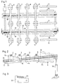
- FIGS. 1 and 2, 2, 3, 4, 5 strand sections are indicated, which are ready on run-out roller tables 6, 7, 8, 9 to be brought onto an adjacent cooling bed 11 by transverse conveying.
- the cooling bed 11 is shown in Fig. 1 by three carriers. It can be stationary or designed as a reversible cooling bed etc.
- two carriages 12 and 12 'belonging to the transverse conveying direction are provided. These carriages 12, 12 'can be moved on a plane 13 inclined to the horizontal by means of a movement device 15. It consists of a double-acting cable winch 17 for the forward and backward movement of the carriage.
- Wheels 18 run on flange surfaces of supports 19, 19 '.
- the carriage 12 can be provided with one or more contact surfaces 21 for the strand sections 2 to 5.
- each run-out roller table 6 to 9 is assigned its own contact surface 21. They are designed in the shape of stairs.
- the contact surfaces 21 are wider than the cross-sectional width of the strand sections 2 to 5. They remain isolated, as shown in dash-dotted lines on the right in FIG. H. lie on the wagon at a predetermined mutual distance.
- the angle of the inclined plane 13 to the horizontal and the height between the bearing surfaces 21 and a roller table plane 23 of the outlet roller tables 6 to 9 are mutually coordinated.
- the contact surface 21 of the carriages 12, 12 'assigned to each run-out roller table 6 to 9 must in the respective clearing position for the sections 2 to 5 essentially correspond to the height of the roller table plane 23.
- the inclined plane 13 has an angle a to the horizontal of less than 10 ° and rises in the transverse conveying direction 25.
- a vertically movable unloading device 26 is assigned in the end position, as shown in broken lines in FIG. 2.
- This unloading device 26 can also be designed as a walking beam bed with an additional horizontal component.
- the inclined plane formed by support 19 can be pivoted at one end about an axis 35 to a foundation bearing and can be provided with a lifting device 36 at the other end.
- This lifting device makes it possible to change the inclination of the supports 19.
- self-unloading which can be achieved by such a lowering
- the supports 19 are lowered to such an extent that the carriages 12 can dive completely below the roller table level 23.
- FIG. 1 shows a carriage 32 which, instead of the step-shaped support surfaces, has a support surface 33 which is common to all strand sections 2 to 5 and slopes in the transverse conveying direction 25.
Landscapes
- Engineering & Computer Science (AREA)
- Mechanical Engineering (AREA)
- Rollers For Roller Conveyors For Transfer (AREA)
- Specific Conveyance Elements (AREA)
- Heat Treatments In General, Especially Conveying And Cooling (AREA)
Description
- Die Erfindung betrifft eine Vorrichtung zum Querfördern von Metallabschnitten, insbesondere von Strangabschnitten von Auslaufrollgängen in einer Stahlstranggiessanlage, wobei mindestens zwei Auslaufrollgänge für Metallabschnitte nebeneinander angeordnet sind und zum Abräumen der Metallabschnitte auf den Auslaufrollgängen sowie zum Übergeben auf ein Kühlbett die Querfördervorrichtung vorgesehen ist.
- Bei Walzwerken und Stranggiessanlagen werden abgelängte Knüppel, Vorblöcke und Brammenriegel durch Querförderung von Auslaufrollgängen abgeschoben und auf ein Kühlbett gebracht. Sind mehrere Auslaufrollgänge nebeneinander angeordnet, werden die Strangabschnitte durch Abschieber gemeinsam auf ein nebengeordnetes Kühlbett geschoben. Zur Überbrückung der Zwischenräume zwischen den Rollgängen sind in der Regel Gleitkufen angeordnet, so dass sich eine Gleitebene bis zum Kühlbett bildet. Solche Gleitkufen werden durch mechanische und thermische Betriebseinflüsse in ihrer Höhenlage zu den Rollgangsrollen verändert. Es besteht daher die Gefahr, dass die Strangabschnitte entweder an vorstehenden Gleitkufen oder Rollen festhaken und diese abreissen. Derartige Schäden können auch bereits durch verzogene bzw. beim Schnitt deformierte Abschnitte verursacht werden.
- Es ist weiter eine Vorrichtung zum Übergeben von Strangabschnitten von Auslaufrollgängen einer Mehrstranggiessanlage auf ein nebengeordnetes Kühlbett bekannt (DE-PS2555280). Auch bei dieser Anlage ist ein Abschiebelineal zum Querfördern der Strangabschnitte vorgesehen. Die in Querförderrichtung angeordneten Gleitschienen sind mittels eines Hubantriebes im Sinne einer Parallelverschiebung bis oberhalb einer Auflageebene der Auslaufrollgänge anhebbar. Nach der durchgeführten Querverschiebung der Strangabschnitte werden die Gleitschienen durch Parallelverschiebung wieder in eine Ruhelage abgesenkt, die unterhalb der Auflageebene der Auslaufrollgänge liegt. Auch bei dieser Vorrichtung reiben die Knüppel entlang der Gleitschiene, so dass ein entsprechender Verschleiss nicht vermeidbar ist. Im weiteren sind für das Querfördern der Strangabschnitte eine Hubeinrichtung und zusätzlich eine Bewegungseinrichtung für das Abschiebelineal notwendig. Durch diese beiden Antriebsaggregate wird die Querfördereinrichtung kostspielig. Beim Abschieben mehrerer Stränge mit dem genannten Abschiebelineal werden die Strangabschnitte zusammengeschoben, und es sind oftmals anschliessend wieder Vereinzelungseinrichtungen notwendig, um die zusammengeschobenen Stränge wieder auf einem Kühlrechen zu verteilen.
- Der Erfindung liegt die Aufgabe zugrunde, eine Vorrichtung zum Querfördern von Metallabschnitten zu schaffen, die die genannten Nachteile überwindet. Insbesondere soll eine Querfördereinrichtung geschaffen werden, die nur minimalen Verschleiss aufweist, nur geringe Quertransportkräfte erfordert, ein Minimum an Bewegungseinrichtungen benötigt und die Stränge auf eine vorbestimmte Distanz zusammenschiebt, dass sie ohne weitere Vereinzelung von einem Wendekühlbett übernommen werden können.
- Gemäss der Erfindung wird diese Aufgabe durch die Summe der Merkmale von Patentanspruch 1 erreicht.
- Mit der erfindungsgemässen Querfördervorrichtung werden die genannten Probleme bezüglich der Reibung zwischen Strang und stationärer Gleitschiene gelöst. Die erforderlichen Kräfte für die Querverschiebung sind relativ klein, weil die gesamte Querverschiebung auf einer rollenden Bewegung basiert. Im weiteren genügt ein einfacher und leistungsschwacher Antrieb für die Querförderung der Metallabschnitte. Zusätzliche Bewegungskomponenten sind nicht erforderlich. Der Gesamtaufbau der Anlage ist mit einfachen und preisgünstigen Komponenten herstellbar.
- Der Neigungswinkel der geneigten Ebene kann leicht den örtlichen Verhältnissen angepasst werden. Die Erfindung schlägt jedoch vor, die geneigte Ebene zur Horizontalen in einem Winkel von weniger als 10° anzuordnen und diese Ebene in Querförderrichtung ansteigen zu lassen. Die Auflageflächen am Wagen können auf verschiedene Weise gestaltet werden. In der Regel werden diese Auflageflächen je nach der Art der Übergabe auf das Kühlbett gestaltet. Gemäss einem weiteren Merkmal der Erfindung ist es von Vorteil, wenn jedem Auslaufrollgang eine eigene, treppenartig angeordnete Auflagefläche zugewiesen ist.
- Mit der erfindungsgemässen Vorrichtung ist es möglich, die Strangabschnitte während der Querförderung in einer gewünschten Distanz voneinander auf ein nebengeordnetes Kühlbett oder ein Wendekühlbett abzugeben. Als zusätzliches Ausführungsbeispiel wird vorgeschlagen, die Auflageflächen und die geneigte Ebene gegenseitig so abzustimmen, dass die treppenförmigen Auflageflächen breiter als die Strangabschnitte gewählt werden.
- In bestimmten Fällen kann es von Vorteil sein, wenn für alle Strangabschnitte eine gemeinsame, in Querförderrichtung abfallende Auflagefläche vorgesehen ist.
- Der Antrieb für die Bewegung des Wagens kann mit hydraulischen, elektrischen Antriebselementen etc. bewerkstelligt werden. Gemäss einem weiteren Ausführungsbeispiel wird vorgeschlagen, die Einrichtung für die Vor- und Rückwärtsbewegung des Wagens mit einer doppelt wirkenden Drahtseilwinde vorzusehen.
- Zum Entladen des Wagens in der Endstellung wird gemäss einem weiteren Ausführungsbeispiel eine vertikal bewegbare Entladeeinrichtung vorgeschlagen.
- Je nach der Art des nebengeordneten Kühlbettes kann es in bestimmten Fällen von Vorteil sein, wenn sich die Querfördervorrichtung selbst entladen kann. Gemäss einer weiteren Ausführungsform wird vorgeschlagen, dass die geneigte Ebene aus Trägern besteht, die Räder der Wagen führen, und dass diese Träger an einem Ende um eine Achse verschwenkbar angelenkt sind und am andern Ende mit einer Hubeinrichtung zur Veränderung der Neigung versehen sind. Eine solche Hubeinrichtung erlaubt eine Selbstentladung auf ein Kühlbett und zusätzlich eine Rückfahrt des Wagens, wenn bereits wieder neue Stränge auf den Ausförderrollen aufliegen oder in die Querförderstrecke einfahren. Anstelle der Verschwenkbarkeit können die Träger auch andere gewünschte Bewegungscharakteristika ausführen, um die genannten Vorteile zu erreichen.
- Im nachfolgenden werden anhand von Figuren Ausführungsbeispiele der Erfindung beschrieben. Es zeigen:
- Fig. 1 eine Draufsicht auf eine Querfördervorrichtung
- Fig. 2 einen Vertikalschnitt nach der Linie 11-11 der Fig. 1 und
- Fig. 3 ein weiteres Beispiel eines Wagens.
- In den Fig. 1 und 2 sind mit 2, 3, 4, 5 Strangabschnitte bezeichnet, die auf Auslaufrollgängen 6, 7,8,9 bereit liegen, um durch Querförderung auf ein nebengeordnetes Kühlbett 11 gebracht zu werden. Das Kühlbett 11 ist in Fig. 1 andeutungsweise durch drei Träger dargestellt. Es kann stationär oder als Wendekühlbett etc. ausgebildet sein. Zum Abräumen der Strangabschnitte 2 bis 5 auf den Auslaufrollgängen 6 bis 9 und zum Beladen des Kühlbettes 11 sind zwei zur Querförderrichtung gehörende Wagen 12 und 12' vorgesehen. Diese Wagen 12,12' sind auf einer zur Horizontalen geneigten Ebene 13 mittels einer Bewegungseinrichtung 15 verschiebbar. Sie besteht aus einer doppelt wirkenden Drahtseilwinde 17 für die Vor-und Rückwärtsbewegung des Wagens. Räder 18 laufen auf Flanschflächen von Trägern 19,19'.
- Der Wagen 12 kann mit einer oder mehreren Auflageflächen 21 für die Strangabschnitte 2 bis 5 versehen sein. In diesem Beispiel ist jedem Auslaufrollgang 6 bis 9 eine eigene Auflagefläche 21 zugeordnet. Sie sind in Treppenform ausgebildet. Die Auflageflächen 21 sind breiter als die Querschnittbreite der Strangabschnitte 2 bis 5. Sie bleiben, wie auf der rechten Seite in Fig. 2 strichpunktiert dargestellt, auch nach der Querförderung vereinzelt, d. h. mit vorbestimmtem gegenseitigem Abstand auf dem Wagen liegen.
- Der Winkel der geneigten Ebene 13 zur Horizontalen und die Höhe zwischen den Auflageflächen 21 sowie eine Rollgangebene 23 der Auslaufrollgänge 6 bis 9 sind gegenseitig abgestimmt. Die jedem Auslaufrollgang 6 bis 9 zugeordnete Auflagefläche 21 der Wagen 12, 12' muss in der jeweiligen Abräumposition für die Abschnitte 2 bis 5 im wesentlichen mit der Höhe der Rollgangebene 23 übereinstimmen. Die geneigte Ebene 13 weist in den meisten Fällen einen Winkel a zur Horizontalen von weniger als 10° auf und steigt in Querförderrichtung 25 an.
- Zum Entladen der beiden Wagen 12, 12' ist in der Endstellung, wie strichpunktiert in Fig. 2 dargestellt, eine vertikal bewegbare Entladeeinrichtung 26 zugeordnet. Diese Entladeeinrichtung 26 kann auch als Hubbalkenbett mit zusätzlicher Horizontalkomponente ausgebildet sein.
- Die durch Träger 19 gebildete, geneigte Ebene kann an einem Ende um eine Achse 35 verschwenkbar an einem Fundamentlager angelenkt und am andern Ende mit einer Hubvorrichtung 36 versehen werden. Durch diese Hubvorrichtung wird es möglich, die Neigung der Träger 19 zu verändern. Neben einer Selbstentladung, die durch ein solches Absenken erreicht werden kann, wird es zusätzlich möglich, die Rückfahrt der Wagen 12, 12' zu bewerkstelligen, wenn bereits wieder Strangabschnitte 2 bis 5 auf die einzelnen Auslaufrollgänge 6 bis 9 eingefahren sind. Die Träger 19 werden in diesem Fall so weit abgesenkt, dass die Wagen 12 vollständig unterhalb die Rollgangebene 23 tauchen können.
- Anstelle einer Vor- und Rückwärtsbewegung der Wagen 12, 32 kann es in bestimmten Fällen von Vorteil sein, die Wagen auf einer endlosen Führung anzuordnen und in einer Kreislaufbewegung zurückzuführen. Eine solche Rückführung der Wagen 12, 32 unterhalb der Auslaufrollgänge würde es ebenfalls ermöglichen, Strangabschnitte auf die Auslaufrollgänge einlaufen zu lassen, bevor die Wagen zurückgeführt sind.
- In Fig. ist ein Wagen 32 dargestellt, der anstelle der treppenförmig ausgebildeten Auflageflächen eine für alle Strangabschnitte 2 bis 5 gemeinsame, in Querförderrichtung 25 abfallende Auflagefläche 33 aufweist.
Claims (8)
Applications Claiming Priority (2)
| Application Number | Priority Date | Filing Date | Title |
|---|---|---|---|
| US06/487,207 US4518074A (en) | 1983-04-21 | 1983-04-21 | Arrangement and a method for transferring products in metal processing installations |
| US487207 | 1983-04-21 |
Publications (2)
| Publication Number | Publication Date |
|---|---|
| EP0126280A1 EP0126280A1 (de) | 1984-11-28 |
| EP0126280B1 true EP0126280B1 (de) | 1987-07-15 |
Family
ID=23934810
Family Applications (1)
| Application Number | Title | Priority Date | Filing Date |
|---|---|---|---|
| EP84104152A Expired EP0126280B1 (de) | 1983-04-21 | 1984-04-12 | Vorrichtung zum Querfördern von Metallabschnitten, insbesondere von Strangabschnitten in einer Stahlstranggiessanlage |
Country Status (4)
| Country | Link |
|---|---|
| US (1) | US4518074A (de) |
| EP (1) | EP0126280B1 (de) |
| CA (1) | CA1222968A (de) |
| DE (1) | DE3464706D1 (de) |
Cited By (1)
| Publication number | Priority date | Publication date | Assignee | Title |
|---|---|---|---|---|
| CN106799398B (zh) * | 2016-12-22 | 2018-09-04 | 承德建龙特殊钢有限公司 | 一种钢坯冷床 |
Families Citing this family (8)
| Publication number | Priority date | Publication date | Assignee | Title |
|---|---|---|---|---|
| DE3905641A1 (de) * | 1989-02-21 | 1990-08-30 | Mannesmann Ag | Vorrichtung zum be- und entladen von lastwagen mit paletten |
| DE4404017C2 (de) * | 1994-02-09 | 1996-06-13 | Moellers Maschf Gmbh | Verfahren und Vorrichtung zum Palettieren von Stückgütern |
| CN101837446A (zh) * | 2010-05-19 | 2010-09-22 | 海安县万力铸造有限公司 | 多工位输送小车 |
| CN102491081A (zh) * | 2011-11-23 | 2012-06-13 | 中冶华天工程技术有限公司 | 钢坯运送方法及装置 |
| AT515257B1 (de) * | 2013-10-22 | 2017-09-15 | Primetals Technologies Austria GmbH | Ausfördern von Langprodukten aus dem Auslaufbereich einer mehrsträngigen Stranggießmaschine in einen Kühlbereich |
| CN108455144B (zh) * | 2017-08-25 | 2020-09-01 | 中国国际海运集装箱(集团)股份有限公司 | 靠边输送装置及其控制方法 |
| CN117772811B (zh) * | 2024-02-27 | 2024-05-10 | 东北大学 | 一种推床预摆控制方法、装置、设备及介质 |
| CN117804294B (zh) * | 2024-02-27 | 2024-05-03 | 保融盛维(沈阳)科技有限公司 | 一种工业电子雷管周身全面检测机构 |
Family Cites Families (9)
| Publication number | Priority date | Publication date | Assignee | Title |
|---|---|---|---|---|
| DE26248C (de) * | Dr. H. grouven in Leipzig | Mantelofen zur Gewinnung der Oxyde des Calciums, Bariums, Strontiums und Magnesiums und von reiner Kohlensäure oder Schwefelwasserstoffgas aus den entsprechenden Karbonaten Qder Pyriten | ||
| DE1805239B2 (de) * | 1968-10-25 | 1976-11-25 | Schloemann-Siemag AG, 4000 Düsseldorf | Einer mehrstranggiessanlage nachgeordnete quertransporteinrichtung fuer abgetrennte strangabschnitte |
| SU425781A1 (ru) * | 1972-10-17 | 1974-04-30 | В. Т. Долганов , Б. Р. Деменев | Брусоперекладчик |
| DE2555280C2 (de) * | 1975-12-09 | 1982-12-16 | SMS Schloemann-Siemag AG, 4000 Düsseldorf | Vorrichtung zum Übergeben von Strangabschnitten von den Auslaufrollgängen einer Mehrstranggießanlage auf ein nebengeordnetes Kühlbett |
| DE2632714C2 (de) * | 1976-07-21 | 1982-12-16 | SMS Schloemann-Siemag AG, 4000 Düsseldorf | Vorrichtung zum Übergeben von Strangabschnitten von den Auslaufrollgängen einer Mehrstranggießanlage auf ein nebengeordnetes Kühlbrett |
| DE2829063A1 (de) * | 1978-07-01 | 1980-01-10 | Schloemann Siemag Ag | Querfoerdereinrichtung zum uebergeben von brammen und blechen |
| DE3009743A1 (de) * | 1980-03-14 | 1981-09-24 | Wolfram Ing.(grad.) 6606 Gersweiler Dewes | Querfoerdervorrichtung, insbesondere kuehlbett fuer stabmaterial oder bleche mit verringerter antriebsleistung |
| DD151288A1 (de) * | 1980-06-09 | 1981-10-14 | Basse Klaus Von | Vorrichtung zum querfoerdern von material |
| CH650218A5 (de) * | 1981-05-05 | 1985-07-15 | Inventio Ag | Uebergabeeinrichtung fuer paletten und stueckgueter. |
-
1983
- 1983-04-21 US US06/487,207 patent/US4518074A/en not_active Expired - Lifetime
-
1984
- 1984-04-12 DE DE8484104152T patent/DE3464706D1/de not_active Expired
- 1984-04-12 EP EP84104152A patent/EP0126280B1/de not_active Expired
- 1984-04-19 CA CA000452368A patent/CA1222968A/en not_active Expired
Cited By (1)
| Publication number | Priority date | Publication date | Assignee | Title |
|---|---|---|---|---|
| CN106799398B (zh) * | 2016-12-22 | 2018-09-04 | 承德建龙特殊钢有限公司 | 一种钢坯冷床 |
Also Published As
| Publication number | Publication date |
|---|---|
| CA1222968A (en) | 1987-06-16 |
| EP0126280A1 (de) | 1984-11-28 |
| DE3464706D1 (en) | 1987-08-20 |
| US4518074A (en) | 1985-05-21 |
Similar Documents
| Publication | Publication Date | Title |
|---|---|---|
| DE888076C (de) | Foerdervorrichtung | |
| EP0654425A1 (de) | Verfahren zum Ein- oder Auslagern bzw. Umstapeln von Trägern für Fördergut in bzw. aus einem mehretagigen Lager und eine Vorrichtung zur Durchführung des Verfahrens | |
| DE3207860A1 (de) | Foerdereinrichtung fuer eine lagerhausanlage | |
| DE1684789B2 (de) | Vorrichtung zum Speichern von Fahrzeugen und dgl | |
| EP0064179A1 (de) | Übergabeeinrichtung für Paletten und ähnliche Stückgüter | |
| EP0126280A1 (de) | Vorrichtung zum Querfördern von Metallabschnitten, insbesondere von Strangabschnitten in einer Stahlstranggiessanlage | |
| EP0327724B1 (de) | Regalförderzeug und Hochregalanlage hierfür | |
| DE2855982C2 (de) | ||
| DD201576A5 (de) | Vorrichtung zum vereinzeln von staeben | |
| DE3234817C2 (de) | Hochregallager | |
| EP0116152A2 (de) | Vorrichtung zur Einlagerung und Entnahme von stangenförmigem Material | |
| CH661494A5 (de) | Einrichtung zum ein- und auslagern von paletten. | |
| DE3002825A1 (de) | Bodenplatten-anordnung | |
| DE2617255C3 (de) | Anlage zum Handhaben von Gußformen | |
| DE10008300A1 (de) | Transporteinrichtung für Stückgüter | |
| EP0461098A1 (de) | Anlage zum Transportieren von Personen bzw. Gütern | |
| DE3545298A1 (de) | Krabbelwagen und foerdersystem | |
| DE2426354B2 (de) | Vorrichtung zum quertransport von langgestrecktem walzgut | |
| DE595507C (de) | Abhebevorrichtung fuer Seiltransportbahnen | |
| DE2555280C2 (de) | Vorrichtung zum Übergeben von Strangabschnitten von den Auslaufrollgängen einer Mehrstranggießanlage auf ein nebengeordnetes Kühlbett | |
| DE3641671C2 (de) | ||
| DE20008073U1 (de) | Anlage zum Fördern und Lagern von Paletten in einem Gestell | |
| AT402815B (de) | Vorrichtung zur speicherung der fahrbetriebsmittel einer seilbahnanlage | |
| DE4411870A1 (de) | Einrichtung zum Umladen von Transportträgern für den Gütertransport | |
| DE60000268T2 (de) | Förderband für den Ausstiegsbereich einer Skiliftanlage |
Legal Events
| Date | Code | Title | Description |
|---|---|---|---|
| PUAI | Public reference made under article 153(3) epc to a published international application that has entered the european phase |
Free format text: ORIGINAL CODE: 0009012 |
|
| AK | Designated contracting states |
Designated state(s): BE CH DE FR GB IT LI |
|
| 17P | Request for examination filed |
Effective date: 19850403 |
|
| 17Q | First examination report despatched |
Effective date: 19860513 |
|
| ITF | It: translation for a ep patent filed | ||
| GRAA | (expected) grant |
Free format text: ORIGINAL CODE: 0009210 |
|
| AK | Designated contracting states |
Kind code of ref document: B1 Designated state(s): BE CH DE FR GB IT LI |
|
| ET | Fr: translation filed | ||
| REF | Corresponds to: |
Ref document number: 3464706 Country of ref document: DE Date of ref document: 19870820 |
|
| PLBE | No opposition filed within time limit |
Free format text: ORIGINAL CODE: 0009261 |
|
| STAA | Information on the status of an ep patent application or granted ep patent |
Free format text: STATUS: NO OPPOSITION FILED WITHIN TIME LIMIT |
|
| 26N | No opposition filed | ||
| PGFP | Annual fee paid to national office [announced via postgrant information from national office to epo] |
Ref country code: FR Payment date: 19890308 Year of fee payment: 6 |
|
| PGFP | Annual fee paid to national office [announced via postgrant information from national office to epo] |
Ref country code: BE Payment date: 19890328 Year of fee payment: 6 |
|
| PGFP | Annual fee paid to national office [announced via postgrant information from national office to epo] |
Ref country code: GB Payment date: 19890331 Year of fee payment: 6 Ref country code: DE Payment date: 19890331 Year of fee payment: 6 |
|
| ITTA | It: last paid annual fee | ||
| PG25 | Lapsed in a contracting state [announced via postgrant information from national office to epo] |
Ref country code: LI Effective date: 19890430 Ref country code: CH Effective date: 19890430 |
|
| REG | Reference to a national code |
Ref country code: CH Ref legal event code: PL |
|
| PG25 | Lapsed in a contracting state [announced via postgrant information from national office to epo] |
Ref country code: GB Effective date: 19900412 |
|
| PG25 | Lapsed in a contracting state [announced via postgrant information from national office to epo] |
Ref country code: BE Effective date: 19900430 |
|
| BERE | Be: lapsed |
Owner name: CONCAST SERVICE UNION A.G. Effective date: 19900430 |
|
| GBPC | Gb: european patent ceased through non-payment of renewal fee | ||
| PG25 | Lapsed in a contracting state [announced via postgrant information from national office to epo] |
Ref country code: FR Effective date: 19901228 |
|
| PG25 | Lapsed in a contracting state [announced via postgrant information from national office to epo] |
Ref country code: DE Effective date: 19910101 |
|
| REG | Reference to a national code |
Ref country code: FR Ref legal event code: ST |