EP0125444B1 - Zeitrelais - Google Patents
Zeitrelais Download PDFInfo
- Publication number
- EP0125444B1 EP0125444B1 EP84103376A EP84103376A EP0125444B1 EP 0125444 B1 EP0125444 B1 EP 0125444B1 EP 84103376 A EP84103376 A EP 84103376A EP 84103376 A EP84103376 A EP 84103376A EP 0125444 B1 EP0125444 B1 EP 0125444B1
- Authority
- EP
- European Patent Office
- Prior art keywords
- armature
- toothed segment
- pinion
- toothed
- timing relay
- Prior art date
- Legal status (The legal status is an assumption and is not a legal conclusion. Google has not performed a legal analysis and makes no representation as to the accuracy of the status listed.)
- Expired
Links
Images
Classifications
-
- H—ELECTRICITY
- H01—ELECTRIC ELEMENTS
- H01H—ELECTRIC SWITCHES; RELAYS; SELECTORS; EMERGENCY PROTECTIVE DEVICES
- H01H43/00—Time or time-programme switches providing a choice of time-intervals for executing one or more switching actions and automatically terminating their operation after the programme is completed
- H01H43/10—Time or time-programme switches providing a choice of time-intervals for executing one or more switching actions and automatically terminating their operation after the programme is completed with timing of actuation of contacts due to a part rotating at substantially constant speed
Definitions
- the invention relates to a timing relay with an instant contact.
- the present invention has for its object to provide a timing relay that enables actuation of the instant contact without additional magnetic means.
- a time relay which has a timer driven by the armature of a sliding armature motor via a pinion arranged at the shaft end of the armature and an instant contact which is actuated by a pivotably mounted toothed segment which engages with the pinion when the armature is tightened, wherein the toothed segment has an toothless sliding surface following its toothed area and the shaft end of the armature is subsequently provided with a smooth collar with the diameter of the pinion to the armature towards the armature, such that in a first displacement position of the armature the pinion with the toothed area of the toothed segment combs through it, while the smooth collar of the shaft end then rolls on the toothless sliding surface of the toothed segment in a second displacement position of the armature.
- the invention reduces the wear between the pinion and the toothed segment and also the noise generated in the switch-on position.
- the sliding anchor is held in an intermediate position until after the tooth segment has passed through and, as soon as the slideway is reached, the sliding anchor moves a little way into its end position.
- the toothed segment is spring-loaded in the direction of the rest position. This ensures that the toothed segment automatically and safely returns to the rest position after the timing relay has been switched off.
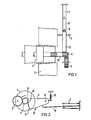
- the sliding armature motor of the timing relay consisting of armature 1 and field winding 2, is used to drive the timing mechanism of the timing relay represented by a gearwheel 3 with the downstream time contacts, not shown in detail. Also not shown in more detail is the mounting of the armature 1, which is in engagement with the pinion 4 with the toothed wheel 3 and, in the tightened state, as shown in FIG. 1, is in operative connection with a toothed segment 5.
- the toothed segment 5 is pivotally mounted about the axis 6 and serves to actuate an immediate contact 7, which is shown as a changeover contact in the exemplary embodiment.
- An extension 8 of the center contact of the instant contact 7 is in operative connection with the toothed segment 5, so that, as shown in FIG.
- the toothed segment 5 is pressed by the spring 9 against the stop 10 into the rest position, i.e. as long as the toothed segment is out of engagement with the pinion 4.
- the toothed segment is provided with a toothed region 12 which is adapted to the toothing 11 of the pinion 4 and which ends in the end region in an toothless sliding surface 13 which slides on a collar 14 of the displacement anchor 1 in the end region of the switching element.
- the armature 1 shifts from the position indicated by dashed lines in FIG. 1 to the extended, i.e. the toothing 11 of the pinion 4 comes into operative connection both with the toothed wheel 3 and with the toothed region 12 of the toothed segment 5.
- the armature 1 has not yet reached its end position, since the toothed region 12 of the toothed segment 5 is lower than the collar 14. After passing through the toothed region 12 of the toothed segment 5, the latter changes into a sliding surface 13 in the end region. As soon as this point is reached, the sliding surface 13 slides on the collar 14, i.e.
- the armature 1 comes to the end position, so that the toothed segment 5 is noiselessly held in the end position until the timer has expired and the timing relay itself is de-energized.
- the prestressed extension 8 of the immediate contact 7 moves in the direction of the upper contact.
- the bias is such that the upper contact is closed before the end position of the toothed segment 5 is reached. If the displacement anchor motor is de-energized, the pinion 4 is released from the gear 3, so that the timer can move back to the rest position in the usual way, and from the toothed segment 5 with the sliding surface 13, see the broken line in FIG. 1, so that the toothed segment 5 also snaps back into the position shown in FIG. 2 due to the force of the spring 9.
- the invention thus creates a simple instant contact for a timing relay that only requires an additional toothed segment, since this can act practically on the same pinion with which the timer itself is driven. The additional effort for this is practically insignificant Weight.
Landscapes
- Transmission Devices (AREA)
- Measurement Of Predetermined Time Intervals (AREA)
- Connection Of Motors, Electrical Generators, Mechanical Devices, And The Like (AREA)
- Gear Transmission (AREA)
Description
- Die Erfindung bezieht sich auf ein Zeitrelais mit einem Sofortkontakt.
- Bei einem bekannten Zeitrelais (DE-B- 2420 651) wird der Sofortkontakt über einen gesonderten, getrennt erregten Elektromagneten beim Einschalten des Zeitrelais betätigt.
- Der vorliegenden Erfindung liegt die Aufgabe zugrunde, ein Zeitrelais zu schaffen, das eine Betätigung des Sofortkontaktes ohne zusätzliche magnetische Mittel ermöglicht.
- Diese Aufgabe wird durch ein Zeitrelais gelöst, das ein vom Anker eines Verschiebeankermotors über ein am Wellenende des Ankers angeordnetes Ritzel angetriebenes Zeitwerk und einen Sofortkontakt aufweist, der von einem verschwenkbar gelagerten, im angezogenen Zustand des Ankers mit dem Ritzel in Eingriff kommenden Zahnsegment betätigt wird, wobei das Zahnsegment im Anschluß an seinen gezahnten Bereich eine ungezahnte Gleitfläche aufweist und das Wellenende des Ankers anschließend an das Ritzel zum Anker hin mit einem glatten Bund mit dem Durchmesser des Ritzels versehen ist, derart, daß in einer ersten Verschiebestellung des Ankers das Ritzel mit dem gezahnten Bereich des Zahnsegmentes - diesen durchlaufend - kämmt, während daran anschließend in einer zweiten Verschiebestellung des Ankers der glatte Bund des Wellenendes auf der ungezahnten Gleitfläche des Zahnsegmentes abrollt.
- Durch die Erfindung ist der Verschleiß zwischen Ritzel und Zahnsegment und auch in der Einschaltlage entstehende Geräusche vermindert. Der Verschiebeanker wird bis nach dem Durchlaufen des Zahnsegmentes in einer Zwischenstellung gehalten und, sobald die Gleitbahn erreicht ist, schiebt sich der Verschiebeanker um ein geringes Stück in seine Endstellung.
- Um eine Schaltverzögerung zu erreichen, ist es an sich bekannt (DE-C 427 424) ein Zahnsegment über eine Bremsscheibe mit einem Kontakt in Wirkverbindung zu bringen.
- Um die Rückstellung des Zahnsegmentes und damit den Sofortkontakt von der Einbaulage des Zeitrelais unabhängig zu machen ist es vorteilhaft, wenn das Zahnsegment in Richtung der Ruhestellung federkraftbelastet ist. Hierdurch ist sichergestellt, daß das Zahnsegment nach Abschalten des Zeitrelais automatisch und sicher in die Ruhestellung zurückkehrt.
- Anhand der Zeichnung ist ein Ausführungsbeispiel gemäß der Erfindung beschrieben und die Wirkung näher erläutert.
- Es zeigen:
- Fig. 1 eine Seitenansich auf die wesentlichen Teile des Zeitrelais im Zusammenhang mit der Erfindung in Prinzipdarstellung,
- Fig. 2 eine Prinzipdarstellung in Draufsicht.
- Der aus Anker 1 und Feldwicklung 2 bestehende Verschiebeankermotor des Zeitrelais dient zum Antrieb des durch ein Zahnrad 3 dargestellten Zeitwerks des Zeitrelais mit den nicht näher dargestellten nachgeschalteten Zeitkontakten. Ebenfalls nicht näher dargestellt ist die Lagerung des Ankers 1, der mit einem Ritzel 4 mit dem Zahnrad 3 in Eingriff steht und zusätzlich im angezogenen Zustand, wie dies Fig. 1 zeigt, mit einem Zahnsegment 5 in Wirkverbindung steht. Das Zahnsegment 5 ist über die Achse 6 schwenkbar gelagert und dient zur Betätigung eines Sofortkontaktes 7, der im Ausführungsbeispiel als Umschaltkontakt dargestellt ist. Eine Verlängerung 8 des Mittenkontaktes des Sofortkontaktes 7 steht mit dem Zahnsegment 5 in Wirkverbindung, so daß, wie Fig. 2 zeigt, der untere Kontakt in der Ruhelage geschlossen ist. Das Zahnsegment 5 wird über die Feder 9 gegen den Anschlag 10 in die Ruhelage gedrückt, d.h. solange das Zahnsegment außer Eingriff mit dem Ritzel 4 ist. Das Zahnsegment ist mit einem der Verzahnung 11 des Ritzels 4 angepaßten gezahnten Bereich 12 versehen, der im Endbereich in eine ungezahnte Gleitfläche 13 ausläuft, die auf einem Bund 14 des Verschiebeankers 1 im Endbereich des Schaltorganes gleitet.
- Wird der Verschiebeankermotor und damit das Zeitrelais an Spannung gelegt, so verschiebt sich der Anker 1 aus der in Fig. 1 gestrichelt angedeuteten Lage in die ausgezogene, d.h. die Zahnung 11 des Ritzels 4 kommt sowohl mit dem Zahnrad 3 als auch mit dem gezahnten Bereich 12 des Zahnsegmentes 5 in Wirkverbindung. Der Anker 1 hat noch nicht seine Endstellung erreicht, da der gezahnte Bereich 12 des Zahnsegmentes 5 tiefer liegt als der Bund 14. Nach Durchlaufen des gezahnten Bereiches 12 des Zahnsegmentes 5 geht dieser im Endbereich in eine Gleitfläche 13 über. Sobald dieser Punkt erreicht ist, gleitet die Gleitfläche 13 auf dem Bund 14, d.h. der Anker 1 kommt in die Endlage, so daß das Zahnsegment 5 geräuschlos in der Endstellung gehalten wird, bis das Zeitwerk abgelaufen ist und das Zeitrelais selbst spannungslos gemacht wird. Beim Bewegen des Zahnsegmentes 5 bewegt sich die vorgespannte Verlängerung 8 des Sofortkontaktes 7 in Richtung auf den oberen Kontakt. Die Vorspannung ist derart, daß der obere Kontakt geschlossen ist, bevor die Endstellung des Zahnsegmentes 5 erreicht ist. Wird der Verschiebeankermotors spannungslos gemacht, so löst sicht das Ritzel 4 sowohl vom Zahnrad 3, so daß sich das Zeitwerk in üblicher Weise in die Ruhestellung zurückbewegen kann, als auch vom Zahnsegment 5 mit der Gleitfläche 13, siehe gestrichelte Darstellung in Fig. 1, so daß auch das Zahnsegment 5 aufgrund der Kraft der Feder 9 in die aus Fig. 2 ersichtliche Lage zurückschnellt.
- Durch die Erfindung ist somit ein einfacher Sofortkontakt für ein Zeitrelais geschaffen worden, der lediglich ein zusätzliches Zahnsegment benötigt, da dies praktisch am gleichen Ritzel angreifen kann, mit dem das Zeitwerk selbst angetrieben wird. Der Mehraufwand hierfür fällt praktisch nicht ins Gewicht.
Claims (3)
Applications Claiming Priority (2)
| Application Number | Priority Date | Filing Date | Title |
|---|---|---|---|
| DE3313745A DE3313745C2 (de) | 1983-04-15 | 1983-04-15 | Zeitrelais |
| DE3313745 | 1983-04-15 |
Publications (3)
| Publication Number | Publication Date |
|---|---|
| EP0125444A2 EP0125444A2 (de) | 1984-11-21 |
| EP0125444A3 EP0125444A3 (en) | 1984-12-19 |
| EP0125444B1 true EP0125444B1 (de) | 1987-07-22 |
Family
ID=6196529
Family Applications (1)
| Application Number | Title | Priority Date | Filing Date |
|---|---|---|---|
| EP84103376A Expired EP0125444B1 (de) | 1983-04-15 | 1984-03-27 | Zeitrelais |
Country Status (2)
| Country | Link |
|---|---|
| EP (1) | EP0125444B1 (de) |
| DE (2) | DE3313745C2 (de) |
Families Citing this family (1)
| Publication number | Priority date | Publication date | Assignee | Title |
|---|---|---|---|---|
| GB2399455B (en) * | 2003-03-14 | 2006-08-09 | Yap Pit Yong | Structure of a synchronous reciprocating tracking device |
Family Cites Families (5)
| Publication number | Priority date | Publication date | Assignee | Title |
|---|---|---|---|---|
| FR427197A (fr) * | 1910-11-14 | 1911-07-28 | Siemens Ag | Relais à temps avec aimant tournant et dispositif retardateur |
| DE427424C (de) * | 1924-09-28 | 1926-04-08 | Asea Ab | Induktionsrelais |
| DE1410145B2 (de) * | 1959-03-20 | 1972-11-02 | Holzer, Walter, 7758 Meersburg | Anordnung zur schnellen einstellung mit anschliessendem programmablauf bei einer vollautomatischen waschmaschinensteuerung |
| DE2420651C2 (de) * | 1974-04-29 | 1982-01-28 | Siemens AG, 1000 Berlin und 8000 München | Zeitrelais mit elektromotorischem Antrieb |
| FR2309029A1 (fr) * | 1975-04-24 | 1976-11-19 | Crouzet Sa | Minuterie electromecanique |
-
1983
- 1983-04-15 DE DE3313745A patent/DE3313745C2/de not_active Expired
-
1984
- 1984-03-27 DE DE8484103376T patent/DE3464985D1/de not_active Expired
- 1984-03-27 EP EP84103376A patent/EP0125444B1/de not_active Expired
Also Published As
| Publication number | Publication date |
|---|---|
| EP0125444A2 (de) | 1984-11-21 |
| EP0125444A3 (en) | 1984-12-19 |
| DE3313745C2 (de) | 1985-02-21 |
| DE3464985D1 (en) | 1987-08-27 |
| DE3313745A1 (de) | 1984-10-25 |
Similar Documents
| Publication | Publication Date | Title |
|---|---|---|
| EP0757193A1 (de) | Elektrische Schaltvorrichtung für Wechselgetriebe von Kraftfahrzeugen | |
| DE1790340A1 (de) | Zeitschaltgeraet | |
| EP0243883A1 (de) | Gurtaufroller | |
| DE3313745C2 (de) | Zeitrelais | |
| DE1680194C3 (de) | Wischanlage für Scheiben von Fahrzeugen | |
| DE690175C (de) | Fahrzeug fuer elektrische Spielzeugeisenbahnen mit Fernsteuerung mittels eines durch Stromstoesse beeinflussten Schaltmagneten | |
| DE2407391B2 (de) | Einrichtung zur Stillsetzung eines Antriebsmechanismus in einem Tonbandgerät | |
| DE3340580C2 (de) | ||
| DE2160301A1 (de) | Zeitrelais mit elektromotorischem antrieb | |
| DE2348899A1 (de) | Vorrichtung zum steuern des anpressdruckes einer rotierenden waschbuerste von waschvorrichtungen fuer fahrzeuge | |
| AT406258B (de) | Bauaufzug | |
| DE2616690C3 (de) | Elektromechanisches Zeitschaltwerk | |
| DE2917038A1 (de) | Elektromagnetisches relais | |
| DE313369C (de) | ||
| DE2203069C3 (de) | Rundsteuerempfänger, der empfangene Startimpulse auf ihre vorgegebene Länge prüft | |
| DE2209347C3 (de) | Schiebeankermotor | |
| DE600478C (de) | Schaltungsanordnung zur Feststellung des vorzeichenrichtigen Unterschiedes von Zeigerstellungen | |
| DE3149302C2 (de) | ||
| DE548519C (de) | Schalteinrichtung fuer induktive Zugbeeinflussung mit einer Wachsamkeitsvorrichtung | |
| DE2018906A1 (de) | Schraubenfederkupplung für federbelastete Verstellvorrichtungen, insbesondere Ventilanordnungen | |
| AT253810B (de) | Steuereinrichtung für Stehbildwerfer | |
| DE1224394B (de) | Motorisch angetriebenes Zeitrelais | |
| DE2362746C3 (de) | Steuereinrichtung für eine Kupplung für binäre Stellglieder, insbesondere für die Einstellung eines Typenträgers | |
| DE2259773B1 (de) | Rundsteuerempfaenger fuer nach dem impulsabstandsverfahren arbeitende anlagen | |
| DE1092679B (de) | Steuervorrichtung fuer ein Tonbandgeraet |
Legal Events
| Date | Code | Title | Description |
|---|---|---|---|
| PUAI | Public reference made under article 153(3) epc to a published international application that has entered the european phase |
Free format text: ORIGINAL CODE: 0009012 |
|
| PUAL | Search report despatched |
Free format text: ORIGINAL CODE: 0009013 |
|
| AK | Designated contracting states |
Designated state(s): DE FR IT |
|
| AK | Designated contracting states |
Designated state(s): DE FR IT |
|
| 17P | Request for examination filed |
Effective date: 19850205 |
|
| GRAA | (expected) grant |
Free format text: ORIGINAL CODE: 0009210 |
|
| AK | Designated contracting states |
Kind code of ref document: B1 Designated state(s): DE FR IT |
|
| REF | Corresponds to: |
Ref document number: 3464985 Country of ref document: DE Date of ref document: 19870827 |
|
| ET | Fr: translation filed | ||
| ITF | It: translation for a ep patent filed | ||
| PLBE | No opposition filed within time limit |
Free format text: ORIGINAL CODE: 0009261 |
|
| STAA | Information on the status of an ep patent application or granted ep patent |
Free format text: STATUS: NO OPPOSITION FILED WITHIN TIME LIMIT |
|
| 26N | No opposition filed | ||
| PGFP | Annual fee paid to national office [announced via postgrant information from national office to epo] |
Ref country code: DE Payment date: 19890529 Year of fee payment: 6 |
|
| PG25 | Lapsed in a contracting state [announced via postgrant information from national office to epo] |
Ref country code: FR Free format text: LAPSE BECAUSE OF NON-PAYMENT OF DUE FEES Effective date: 19891130 |
|
| REG | Reference to a national code |
Ref country code: FR Ref legal event code: ST |
|
| PG25 | Lapsed in a contracting state [announced via postgrant information from national office to epo] |
Ref country code: DE Effective date: 19901201 |